1. ZJ BATTERY/STARTER/GENERATOR SERVICE 8B - 1
BATTERY/STARTER/GENERATOR SERVICE
CONTENTS
page page
BATTERY . . . . . . . . . . . . . . . . . . . . . . . . . . . . . . . 1 SPECIFICATIONS . . . . . . . . . . . . . . . . . . . . . . . . . 8
GENERATOR . . . . . . . . . . . . . . . . . . . . . . . . . . . . 6 STARTER AND STARTER RELAY . . . . . . . . . . . . . 4
GENERAL INFORMATION tery/Starting/Charging Systems Diagnostics. Refer to
Group 8B covers battery, starter and generator ser- Group 8W - Wiring Diagrams for complete circuit de-
vice procedures. For diagnosis of these components scriptions and diagrams.
and their related systems, refer to Group 8A - Bat-
BATTERY
GENERAL INFORMATION
This section covers battery service procedures only.
For battery maintenance procedures, refer to Group 0
- Lubrication and Maintenance. While battery charg-
ing can be considered a service or maintenance pro-
cedure, this information is located in Group 8A -
Battery/Starting/Charging Systems Diagnostics. This
was done because the battery must be fully charged
before any diagnosis is performed.
It is important that the battery, starting, and
charging systems be thoroughly tested and inspected
any time a battery needs to be charged or replaced.
The cause of abnormal discharge, over-charging, or
premature failure of the battery must be diagnosed
and corrected before a battery is replaced or returned
to service. Refer to Group 8A - Battery/Starting/ Fig. 1 Low-Maintenance Battery
Charging Systems Diagnostics. (2) Loosen the cable terminal clamps and remove
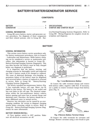
The factory installed low-maintenance battery (Fig. both battery cables, negative cable first. If necessary,
1) has removable battery cell caps. Water can be use a puller to remove terminal clamps from battery
added to this battery. The battery is not sealed and posts (Fig. 2).
has vent holes in the cell caps. The chemical compo-
sition within the low-maintenance battery reduces
battery gassing and water loss at normal charge and
discharge rates. Therefore, the battery should not re-
quire additional water in normal service.
However, low electrolyte can be caused by an over-
charging condition. Be certain to diagnose charging
system before returning vehicle to service. Refer to
Group 8A - Battery/Starting/Charging Systems Diag-
nostics for more information.
BATTERY REMOVE/INSTALL
(1) Turn ignition switch to OFF position. Make Fig. 2 Remove Battery Terminal Clamp
sure all electrical accessories are off. (3) Inspect the cable terminals for corrosion and
damage. Remove corrosion using a wire brush or post
2. 8B - 2 BATTERY/STARTER/GENERATOR SERVICE ZJ
and terminal cleaning tool, and a sodium bicarbonate
(baking soda) and warm water cleaning solution (Fig.
3). Replace cables that have damaged or deformed
terminals.
Fig. 3 Clean Battery Cable Terminal
WARNING: WEAR A SUITABLE PAIR OF RUBBER Fig. 4 Battery Tray and Holddown
GLOVES (NOT THE HOUSEHOLD TYPE) WHEN RE-
MOVING A BATTERY BY HAND. SAFETY GLASSES
SHOULD ALSO BE WORN. IF THE BATTERY IS
CRACKED OR LEAKING, THE ELECTROLYTE CAN
BURN THE SKIN AND EYES.
(4) Remove battery holddowns (Fig. 4) and remove
battery from vehicle.
(5) Inspect battery tray (Fig. 4) and holddowns for
corrosion or damage. Remove corrosion using a wire
brush and a sodium bicarbonate (baking soda) and
warm water cleaning solution. Paint any exposed
bare metal and replace any damaged parts.
(6) Inspect the battery case for cracks or other
damage that could result in electrolyte leaks. Also
check battery terminal posts for looseness. Batteries
with damaged cases or loose posts must be replaced.
Fig. 5 Removing Cell Cap
(7) Check electrolyte level in the battery. Use a
putty knife or other suitable wide-bladed flat tool to Ensure that cleaning solution does not enter cells
pry cell caps off (Fig. 5). Do not use a screwdriver. through the vent holes. If the battery is being re-
Add distilled water to each cell until the liquid placed, refer to Specifications in Group 8A - Battery/
reaches the bottom of the vent well. DO NOT OVER- Starting/Charging Systems Diagnostics to confirm
FILL. If battery is discharged, charge as required. replacement has correct classification and ratings for
Refer to Group 8A - Battery/Starting/Charging Sys- the vehicle.
tems Diagnosis for more information. (9) Clean corrosion from battery posts (Fig. 7) with
(8) If the battery is to be reinstalled, clean outside a wire brush or post and terminal cleaner, and so-
of battery case and top cover with sodium bicarbon- dium bicarbonate (baking soda) and warm water
ate (baking soda) and warm water cleaning solution cleaning solution.
(Fig. 6) to remove acid film. Flush with clean water.
3. ZJ BATTERY/STARTER/GENERATOR SERVICE 8B - 3
Fig. 8 Battery Cable Connections
(11) Loosely install battery holddown hardware.
Ensure that battery base is correctly positioned in
tray, then tighten holddowns to 2.2 N⅐m (20 in. lbs.)
Fig. 6 Clean Battery torque.
CAUTION: Be certain that battery cables are con-
nected to the correct battery terminals. Reverse po-
larity can damage electrical components.
(12) Place oiled felt washer on battery positive ter-
minal post.
(13) Install and tighten battery positive cable ter-
minal clamp. Then install and tighten negative cable
terminal clamp. Both cable clamp bolts require
torque of 8.5 N⅐m (75 in. lbs.).
(14) Apply a thin coating of petroleum jelly or
chassis grease to cable terminals and battery posts.
Fig. 7 Clean Battery Post
(10) Position battery in tray. Ensure that positive
and negative posts are correctly positioned. The cable
terminals must reach the correct battery post with-
out stretching (Fig. 8).
4. 8B - 4 BATTERY/STARTER/GENERATOR SERVICE ZJ
STARTER AND STARTER RELAY
GENERAL INFORMATION Power Distribution Center (PDC). Refer to underside
This section covers starter and starter relay service of PDC cover for relay location.
procedures only. For diagnostic procedures, refer to
Group 8A - Battery/Starting/Charging Systems Diag- STARTER REMOVE/INSTALL - 4.0L
nostics. Service procedures for other starting system (1) Disconnect battery negative cable.
components can be found as follows: (2) Raise and support vehicle.
• battery - see Battery, in this group (3) Disconnect battery wire and solenoid feed wire
• ignition switch - refer to Group 8D - Ignition Sys- connector (Fig. 9).
tems
• clutch pedal position switch - refer to Group 6 -
Clutch
• park/neutral position switch (automatic transmis-
sion) - refer to Group 21 - Transmission and Transfer
Case
• wiring harness and connectors - refer to Group 8W
- Wiring Diagrams.
STARTER
The starter motor incorporates several features to
create a reliable, efficient, compact and lightweight
unit. A planetary gear system (intermediate trans-
mission) is used between the electric motor and pin-
ion gear. This feature makes it possible to reduce the
dimensions of the starter. At the same time, it allows
higher armature rotational speed and delivers in-
Fig. 9 Solenoid Harness Remove/Install
creased torque through the pinion gear to the fly-
wheel or drive plate ring gear. (4) Remove starter front mounting bolt (Fig. 10).
The use of a permanent magnet field on 4.0L en-
gine starters also reduces starter size and weight.
This field consists of six high-strength permanent
magnets. The magnets are aligned according to their
polarity and are permanently fixed in the starter
field frame.
The starter motors for all engines are activated by
a solenoid mounted to the overrunning clutch hous-
ing. However, the starter motor/solenoid are serviced
only as a complete assembly. If either component
fails, the entire assembly must be replaced.
This unit is highly sensitive to hammering, shocks
and external pressure.
CAUTION: The starter motor MUST NOT BE
CLAMPED in a vise by the starter field frame. Doing
so may damage the magnets. It may be clamped by
the mounting flange ONLY.
CAUTION: Do not connect starter motor incorrectly
when tests are being performed. The permanent
magnets may be damaged and rendered unservice-
able. Fig. 10 Starter Remove/Install - Typical
(5) Remove starter rear mounting bolt and remove
STARTER RELAY starter.
The starter relay is an International Standards Or- (6) Reverse removal procedures to install and
ganization (ISO) type relay, and is located in the tighten mounting hardware as follows:
5. ZJ BATTERY/STARTER/GENERATOR SERVICE 8B - 5
• starter mounting bolts to 45 N⅐m (33 ft. lbs.)
• terminal adapter solenoid nut to 6 N⅐m (55 in. lbs.)
• terminal adapter battery cable nut to 10 N⅐m (90
in. lbs.).
(7) Remove vehicle support and lower vehicle.
(8) Install negative cable to battery.
STARTER REMOVE/INSTALL - 5.2L
(1) Disconnect battery negative cable.
(2) Raise and support vehicle.
(3) Disconnect the battery wire and solenoid feed
wire connector (Fig. 11).
Fig. 12 Starter Remove/Install - Typical
(2) Remove starter relay by unplugging unit from
PDC (Fig. 13).
Fig. 11 Solenoid Harness Remove/Install - Typical
(4) Remove lower mounting nut (Fig. 12).
(5) Remove transmission line clip from stud.
(6) Remove upper mounting bolt.
(7) Pull starter forward and remove from vehicle.
(8) Reverse removal procedures to install and
tighten mounting hardware as follows:
• starter mounting bolt to 68 N⅐m (50 ft. lbs.)
• starter mounting nut to 27 N⅐m (20 ft. lbs.)
• terminal adapter solenoid nut to 6 N⅐m (55 in. lbs.)
• terminal adapter battery cable nut to 10 N⅐m (90
in. lbs.).
(9) Remove vehicle support and lower vehicle. Fig. 13 Power Distribution Center
(10) Install negative cable to battery. (3) Install starter relay by aligning relay terminals
with cavities in PDC and plugging relay in.
STARTER RELAY REMOVE/INSTALL (4) Connect negative cable to battery.
(1) Disconnect battery negative cable. (5) Test relay operation.
6. 8B - 6 BATTERY/STARTER/GENERATOR SERVICE ZJ
GENERATOR
GENERAL INFORMATION
This section covers generator service procedures
only. For generator or charging system diagnosis, re-
fer to Group 8A - Battery/Starting/Charging Systems
Diagnostics.
The generator is belt-driven by the engine. All en-
gines use serpentine drive. The generator is serviced
only as a complete assembly. If the generator fails for
any reason, the entire assembly must be replaced.
Be certain that the replacement generator has the
same output rating as the original unit. Refer to
Group 8A - Battery/Starting/Charging Systems Diag-
nostics and see Specifications.
The generator field control (voltage regulator) cir-
cuitry is internal to the Powertrain Control Module
(PCM). If faulty, the entire PCM must be replaced.
Refer to Group 14 - Fuel System for PCM service
procedure.
GENERATOR REMOVE/INSTALL - 4.0L
WARNING: DISCONNECT NEGATIVE CABLE FROM Fig. 15 Power Steering Pump Front Mounting Bolts
BATTERY BEFORE REMOVING BATTERY OUTPUT
WIRE FROM GENERATOR. FAILURE TO DO SO (6) Remove generator B+ terminal nut, 2 field ter-
CAN RESULT IN INJURY. minal nuts, ground and harness holddown nuts (Fig.
16). Remove wire connector assembly.
(1) Disconnect battery negative cable.
(2) Loosen rear mounting bolts (Fig. 14).
Fig. 16 Connector Remove/Install
(7) Remove 2 generator mounting bolts and remove
generator from vehicle.
(8) Install generator with two mounting bolts.
Torque bolts to 55 N⅐m (41 ft. lbs.).
(9) Attach generator wires.
Fig. 14 Power Steering Pump Rear Mounting Bolts CAUTION: Never force a belt over a pulley rim us-
(3) Loosen power steering pump pivot bolt and lock ing a screwdriver as the synthetic fiber may be
nut (Fig. 15). damaged.
(4) Loosen adjusting bolt to remove belt.
(5) Raise and support vehicle.
7. ZJ BATTERY/STARTER/GENERATOR SERVICE 8B - 7
CAUTION: When installing a serpentine accessory (3) Rotate the tensioner assembly clockwise (as
drive belt, the belt MUST be routed correctly. The viewed from front) until tension has been relieved
water pump will be rotating in the wrong direction if from belt.
the belt is installed incorrectly, causing the engine (4) Remove belt from vehicle.
to overheat. Refer to the belt routing label in engine (5) Remove lower generator mounting bolt and nut
compartment, or refer to Belt Schematics in Group (Fig. 18).
7 - Cooling System.
(10) Place serpentine belt over pulley.
(11) The 2 rear mounting bolts and the power
steering pump pivot bolt should be finger tight.
(12) Turn adjusting bolt until the belt has the cor-
rect tension. See Belt Tension in Specifications.
(13) Tighten rear mounting bolts, pivot bolt, and
lock nut to 27 N⅐m (20 ft. lbs.) torque.
(14) Remove support and lower vehicle.
(15) Connect negative cable to the battery.
GENERATOR REMOVE/INSTALL - 5.2L
WARNING: FAILURE TO DISCONNECT NEGATIVE
CABLE FROM BATTERY BEFORE DISCONNECTING
RED (OUTPUT) WIRE CONNECTOR FROM GENERA- Fig. 18 Generator Mounting Bolts
TOR CAN RESULT IN INJURY.
(6) Remove upper generator mounting bolt and re-
Drive belts on the 5.2L engine are equipped with a move generator from bracket.
spring loaded automatic belt tensioner (Fig. 17). This (7) Remove the battery output terminal nut, 2 field
belt tensioner is used on all belt configurations. For terminal nuts, ground, and harness holddown nuts
more information, refer to Group 7 - Cooling System, (Fig. 19). Remove wire connectors.
Automatic Belt Tensioner - 5.2L Engines.
(1) Disconnect battery negative cable.
(2) Attach a socket/wrench to the pulley mounting
bolt of the automatic tensioner (Fig. 17).
Fig. 19 Connector Remove/Install
(8) Install harness to replacement generator.
Tighten hardware as follows:
• ground terminal, battery output terminal and wire
Fig. 17 Belt Remove/Install harness holddown nuts - 7-10 N⅐m (60-90 in. lbs.)
• field terminal nuts - 2.5-3 N⅐m (20-30 in. lbs.).
8. 8B - 8 BATTERY/STARTER/GENERATOR SERVICE ZJ
(9) Install generator. Tighten both bolts to 41 N⅐m (11) Attach a socket/wrench to the pulley mounting
(30 ft. lbs.). bolt of the automatic tensioner.
(12) Rotate the socket/wrench clockwise. Place the
CAUTION: When installing a serpentine accessory belt over the idler pulley. Let tensioner rotate back
drive belt, the belt MUST be routed correctly. The into place. Remove wrench. Be sure belt is properly
water pump will be rotating in the wrong direction if seated on all pulleys.
the belt is installed incorrectly, causing the engine
(13) Check belt tensioner indexing marks. Refer to
to overheat. Refer to the belt routing label in engine
Group 7 - Cooling System, Automatic Belt Tensioner.
compartment, or refer to Belt Schematics in Group
7 - Cooling System.
(10) Position the drive belt over all pulleys except
the idler pulley. This pulley is located between the
generator and A/C compressor.
SPECIFICATIONS
BATTERY SPECIFICATIONS GENERATOR SPECIFICATIONS
TORQUE TORQUE
STARTER SPECIFICATIONS
TORQUE - 4.0L