SlideShare a Scribd company logo
1 of 99
Download to read offline
FUTURE RAeS AIR POWER GROUP AIRCRAFT ENGINEERING CONCEPT.
By Geoffrey Wardle. MSc. MSc. CEng. MRAeS. Snr.MAIAA.
PROJECT THOR : - FDSA REQUIREMENTS CAPTURE (STAGE 1).
This is the design concept for a paper I intend to submit to the RAeS Air Power Group in 2022, this
research is to cover the first, three stages of the concept design process: -
1) Requirements capture: - This presentation.
2) Design trade studies: -
3) Preliminary design proposal and structural layout: -
The American Institute of Aeronautics and Astronautics (AIAA) sponsors a collegiate design
competitions (reference 1), which was used as the requirements foundation for a Future Deep
Strike Aircraft. The request for proposals (RFP) for the 2001-2002 team university aircraft design
competition outlined a requirement for a stealth supersonic interdictor to replace the subsonic F-
117, the FB-111, F-15E and even the B-1B and to augment the ATB (now the Northrop B-21
Raider) additions and modifications to this RFP have been made to modernize it as RFP - 997. This
study will use public source material which will be referenced to formulate the FDSA proposal
response and will not contain any ITAR or IP material it is an academic tool for use by such
institutions as the USAFA and the RAFC Cranwell.
I will use USAFA AeroDYNAMIC JD3™ MDO toolset for concept performance analysis, and used
Catia V5.R21 surface, solid (CFC and Metallic structural layout and component design), and
kinematics, and FEA using Nastran 2000, through to preliminary design to the Cranfield
Aerospace Solutions Design Manual CIT/COA/AA0/1 Issue 3 (29/07/99), producing a modular
airframe capable of modification from two manned crew to an unmanned type, and designed for
autonomous assembly, and in service maintenance.
2
Introduction to the FDSA (Thor.) Concept and Preliminary Design Study.
Chart 1:- Weapons System Engineering Concept strategy used in this project.
This design study will employ the Weapons System Engineering Concept strategy to develop this
study within the USAF structured capabilities - based assessment methodology taking the study
from concept to (theoretical) IOC. This will enable evaluation by the USAFA for possible use as an
academic study, below is the Weapons Systems Engineer visualisation V-model to be applied.
3
Develop Systems
Concept, Understand
User Requirements and
Validation plan.
Develop Systems
Performance
Specifications and
Systems Validation plan.
Expand Performance
Specifications into CI
“Design - to” Specifications
and CI Validation plan.
Evolve “Design -to”
Specifications into “Build -
to” Documentation and
Inspection plan.
Fabricate, Assemble and
Code to “Design - to”
Documentation.
Inspect
“Build - to”
Documentation.
Assemble CI’s and
Preform CI Verification
to CI “Design - to”
Specification.
Integrate Systems and
Perform Systems Verification
to Performance
Specifications .
Demonstrate and
Validate Systems to
User Validation plan.
Time
 The purpose of this study is to give lectures of military Airforce institutions such as the USAFA
and RAFC Cranwell a case study of a hypothetical concept Future Deep Strike Aircraft (FDSA)
to use in the teaching of the application of systems engineering principles. The FDSA is
designed for the Penetrating Counter Air / Penetrating Electronic Attack missions, against a
future great power adversary, with a proposed in Initial Operational Capability of 2045. Although
the actual project is hypothetical it is based on current real world threats, technologies, and
emerging capabilities.
 The systems engineering process used in today‟s complex systems - of - systems projects such
as F-35 and F/A-22 projects is a process matured and founded on the principles of weapons
systems development in the past. The examples of systems engineering used on other
programs, past and present provide a wealth of lessons learnt which can be used and applied
to today‟s projects, and this was the thinking behind the FDSA project design study, and the
historic case studies produced by the Centre for Systems Engineering at the Air Force Institute
of Technology (AFIT/SY) Wright - Patterson AFB Ohio, USA.
 The purpose of developing this detailed project case study is to support the teaching of the
application of systems engineering principles, to military aircraft design projects, and to
develop a wider understanding of military aircraft concept design. This will facilitate learning by
emphasizing to the student the vital need to consider the long - term consequences of weapons
systems engineering and programme decisions on project success. The FDSA WSC project
when used with existing AFITY/SY case studies will enable the student to apply learnt
methodologies, tools, processes and tools to determine the outcome of alternatives at the
project / systems level. 4
Learning objectives of the FDSA (Thor.) Concept and Preliminary Design Study.
 Weapons Systems Engineering is the technical engineering and technical management process
that is focused on delivering and sustaining robust high - quality, affordable, high - capability
weapons that meet the needs of the warfighter the USAF in this case (not to be confused with
an individual system on a platform e.g. fuel, or electrical). The process must operate effectively
with desired mission - level capabilities, established system - level requirements allocate these
down to the lowest level of the design, and ensure validation and verification of performance
meeting cost and schedule constraints. The weapons systems engineering process changes as
the project progresses from one phase to the next (see chart 1), as do the tools and procedures
applied.
 The Future Deep Strike Aircraft Weapons System Concept project will in addition to system
engineering will focus on using skills from multiple professions and engineering disciplines (e.g.
concept design, structures, electromagnetics, propulsion, and avionics, etc.) and collecting,
assessing, and integrating varied functional data will be emphasized. Overall the student will be
provided with a near - term real - world based project to apply weapons system concept
engineering and make recommendations in an attempt to balance cost, capability, schedule and
performance criteria.
 The Key learning principles for this study are presented on slides 6 and 7.
5
Learning objectives of the FDSA (Thor.) Concept and Preliminary Design Study.
1) LP.1 - Requirements definition and management: - Are the requirements for the FDSA clear
and realistic, would they be easy to manage and validate?
2) LP.2 - Weapon Systems Architecture and design Trade Off’s: - Is there adequate scope in
the design trade studies in order to achieve in the FDSA a Weapons System Concept that will
be balanced for performance, mission effectiveness, survivability, and cost, at the Technology
Readiness Levels (TRL) and Manufacturing Readiness Levels (MRL) required with the
attendant risk to schedule impacts?
3) LP.3 - Communications and Systems Management : - Has there been full open and detailed
communication between the Air Staff, DoD, AFRC and the contractors design and engineering
teams? Have future maintainers and operational level engineering staff been involved at the
initial requirements and concept stages? Have all issues been raised and dealt with in a way
that is acceptable to all parties. Has there been sound application of systems engineering
principles by the Weapon System Program Office?
4) LP.4 - Validation and Verification: - The FDSA like any complex weapon systems
development program which provides new war-fighting capability, has areas of risk or
deficiency that comes to light during RDT&E, even if it was perceived low risk in the concept
design stage. Have all of the major program risks been identified before moving to the
preliminary design stage for the FDSA? Have all of the testing requirements for the airframe /
powerplants / and systems been identified fully scoped out with planned resourcing and
costing?
6
Key learning principles of the FDSA (Thor.) Concept Study.
5) LP.5 - Risk Planning and Management: - The intention is that the FDSA program is structured
so that risks affecting the viability of the weapons system concept are identified at contract
award and are structured as Work Breakdown Studies (going deeper than design trade studies
in evaluating all relevant issues of the proposed engineering solutions), these feed into the
Integrated Project Teams consisting of design, structures, manufacturing, logistics, maintainers,
weights, cost, and QA engineers. These IPT‟s will interact with USAF/Systems Project Office
specialists to evaluate solutions and assess performance trade-off‟s against schedule costs,
and risk. The initial risks are those “normal” risks associated with a large complex weapons
system development as well as new technology and processes necessary to mature the
program to low to medium risk at PDR. The risk closure process will continue throughout the
FDSA development and identify new risks and continuously identify new risk closure plans.
These plans will show all design, analysis, tests, tooling, and other tasks necessary to close the
identified risk and will be maintained as part of the normal design / program reporting activity.
The student will learn how to assess these plans and if they are developed enough to lower the
risks to an acceptable level of technical maturity for PDR.
Upon completion of this case study the student will have a wide appreciation of what will be
required for the planning and design and development of a near future Combat Air Weapon System
for the USAF.
7
Key learning principles of the FDSA (Thor.) Concept Study.
FDSA PROJECT THOR STAGE 1 CONTENTS.
1) Request For Proposals - 997 Threat Analysis. Slides 9 - 15
2) Potential great and medium power adversaries A2/AD capabilities. Slides 16 - 28
3) Assumptions Made in Defining the FDSA Requirements. Slides 29 - 30
4) FDSA Missions / Key Attributes and Requirements. Slides 30 - 73
5) FDSA Operational Requirements Capture and Analysis Slides 74 - 80
6) Type of Design Selection, Special type: Modification: or New. Slides 81 - 82
7) Key Design Requirement Evaluation. Slides 83 - 92
8) Concepts and Initial Sizing and project future Stages. Slides 93 - 96
9) Reference works. Slides 97 - 99
8
The United States air and naval Combat Air Forces have provided an asymmetric advantage over
its enemies, from the late 1930‟s the United States has been the only nation to create and sustain
an operational fleet of combat aircraft capable of striking targets anywhere on the globe. Over the
last decade of the 20th Century and the first two decades of the 21st Century combat aircraft
equipped with precision - guided munitions, first and second generation stealth technology,
advanced sensors, and other mission systems have played pivotal roles during conflicts in the
Balkans, the Middle East, and South Asia.
In the 2020‟s and beyond the U.S. Department of Defence is at a turning point after a decade of
counterinsurgency warfare, today the US and other major Western nations face the challenge of to
a return to Great Power Competition. America‟s focus on counterinsurgency and non - state
terrorists has given China, Iran, North Korea, and Russia as well as other competitors the action
space to develop anti - access / area denial (A2/AD)² that could threaten U.S. access to areas of
vital interest. The proliferation of long range ballistic, and advanced cruise missiles ( charts 1- 4),
anti - satellite weapons, and cyber threats as Integrated Aerospace Defence Systems (IADS) has
and will constrict and diminish the U.S. military's ability to respond to international crisis in a timely
manner and negate the freedom of action previously employed.
In terms of future air campaigns beyond 2040 these A2/AD capabilities impact on the USAF in that
air dominance in future wars cannot be taken for granted, Command and Control networks may not
be secure, in theatre air bases will be venerable to enemy attack, and non stealthy intelligence,
surveillance, and reconnaissance assets (ISR) and strike aircraft manned or unmanned will suffer
unacceptable losses penetrating contested airspace.
9
Part 1: - Request For Proposals RFP - 997 Threat Analysis.
The Return of Great Power Competition (the New Cold War):- 29 years since the end of the
first Cold War 01 January 1991, the World is moving inexorably towards a new Great Power
Competition which has every indication of not ending as favourably for the West as the last one,
without the West being able to hold the adversaries most important targets at risk. Russia‟s
aggression against Eastern Europe‟s frontline states (Georgia, Ukraine, etc.) and continued probing
of western air defences coupled with a massive build up of conventional and nuclear forces do not
indicate a 1990‟s style coexistence. Also China‟s expansion in East and South China Seas coupled
with massive military expansion and development of hither too western advanced military
technologies, signals a return to Great Power Competition. Russia and China are both manifestly
intent on establishing regional and international in their favour by undermining Western influence in
their respective zones of interest. This will present major challenges to the security of the United
States and its regional allies but also the stability of the international system by limiting the ability of
the US and its allies to intervene in regional crisis by:-
 Restricting or denying the US access to forward bases through either political coercion or the
aggressive threat of precise missile and or air strikes:
 Limiting freedom of movement and manoeuvre for US Navy surface vessel task forces, and
carrier battle groups:
 Degrading US C4ISR networks with kinetic and non kinetic weapons:
 Hobbling US power projection by attacking “soft” logistics targets:
 Limiting the effectiveness of US precision strikes.
10
Request For Proposals RFP - 997 Threat Analysis.
 Precision Strike effectiveness is being limited by the following means:-
 Fielding advanced integrated air defence system (IADS);
 Using strategic depth to move potential targets further inland;
 Hardening and / or deeply burying potential targets;
 Increasing the mobility of key military systems, such as SAM‟s and missile transporter
erector launchers (TEL).
Not only Russia and China are enacting these policies but North Korea, and Iran are playing their
part, see charts 1 through 8 illustrating threats to in theatre basing of precision strike assets.
In continental Europe a revisionist Russia is determine to reform the former Soviet Union and
regain Russia‟s great power status through domination of former Soviet and Warsaw Pact states
either by coercion, or invasion. Thus stopping these states from joining NATO and indeed seeking
to discredit NATO‟s in that it would not be able to deter such Russia actions or defend such nations
from aggression. The perceived requirement of Russia to have a wall of protective “sacrificial”
states is not new and dates back to the post World War 2 division of Europe by the allied nations,
however since the collapse of the former Soviet Union on 26th December 1991, the perception in
the West was that these buffer states would be allowed to choose there own path forward, however
this appears to be no longer the case. In fact in the past 10 years there has been a disturbing
increase in both the intensity of what Russia perceives to be an infiltration in to its territory and it
willingness to use military, economic, cyber, and other elements of its national power to achieve the
objective of reforming its buffer states.
11
Request For Proposals RFP - 997 Threat Analysis.
Russia‟s annexation of Crimea and subsequent invasion of eastern Ukraine has undermine the
normal political foundations of eastern Europe and has put the former Eastern Block nations on
notice that if Russia‟s requirements are not met there will be military consequences, and
precipitated the most serious European crisis since the Balkans war of the 1990‟s. NATO‟s defence
posture and by extension the United States is rapidly losing credibility and the capability to deter a
new Russia intent on using military force as the ultimate means to achieve its national objectives,
and is currently in a vast and on going defence modernisation program, overmatching NATO‟s
frontline states.
The Chinese are also engaged in a extensive military rearmament program with the apparent goal
of extending their power and influence even further beyond their shores destabilizing the military
balance in the region which has enabled unparalleled peace and prosperity in the far east for the
past thirty years. China see military force as an arm of diplomacy not as an alternative, examples of
this can be found the claims on potential oil and gas in the South China Sea (see figure 1), the
continued clashes with Vietnam since the annexation of the Paracel Islands,(now a base for PLAAF
combat aircraft with a 2,500m runway), in Hong Kong‟s assimilation back into main land Chinese
control, the stance China has taken on the disputed Spratly Islands with Vietnam (China has
engaged in a shooting battle that sank two Vietnamese warships killing 70) , and the very real risk
of China‟s assimilation of Taiwan by military means. China would argue that its expansion is
necessary to protect its sea lanes from the west passing through the vital Strait of Malacca (see
figure 2) which for example sees 80% of China‟s imports of crude oil. Troubles within the Exclusive
Economic Zone both in the South China Sea and the East China Sea centre on island disputes and
their potential oil and gas reserves. 12
Request For Proposals RFP - 997 Threat Analysis.
13
Taiwan
Philippines
Malaysia
Vietnam
China
Potential oil and gas fields in the
South China Sea and countries
maritime claims of ownership.
PLAAF airbase on Woody Island one of the
Paracel Islands in the South China Sea for
Su 27 / Su 35 and J-20 Combat Aircraft.
Figure 1: - China‟s key fuel admissions in the South China Sea region.
*Reference: - 2
*Reference: - 2
14
Figure 2: - China‟s need to control sea lanes in the South China Sea region.
*Reference: - 2
All countries around the South China Sea perceive it as an important source income currently from
fishing rights, but they are all eager to claim and explore its potential oil and natural gas reserves.
As can be seen from figure 1 several states have overlapping claims over the South China Sea and
disagreements about the Exclusive Economic Zones (EEZ) have lead to several states occupying
islands in the area without explicitly laying legal claim to the islands in question, hoping that a de
facto land grab will become legitimate over the duration of the occupation. This has raised tensions
in the region when surprise invasions occur, leading to naval battles, political and diplomatic
protests, and seizure of ships and arrest crews entering these disputed areas. The rewards of
these actions are high for example the U.S. Geological survey estimates the total confirmed
discovered and potential undiscovered resources to 28bn barrels of oil, Chinese estimates for the
same area however are much higher in the order of 105bn to 213bn barrels of oil. Although most of
the current finds in the South China Sea are gas deposits and China estimates there are 900 trillion
cubic feet of gas in this region. The two most disputed island groups are the Paracel Islands, and
the Spratly Islands as shown in figure one.
The East China Sea is also an area of 1.2 million Km³ and has disputed large oil and natural gas
deposits, and here the main parties are Japan and China, Taiwan also has claims but is not using
force, and as Japan has virtually no domestic oil or gas reserves these disputed zones are of great
national importance. The East China Sea disagreement has two route causes (1): - all parties
disagree on the determination of Exclusive Economic Zones in the East China Sea, (2): - China,
Japan and Taiwan disagree on the ownership of the Diaoyutai / Senkaku Islands which are
believed to have large oil and natural gas deposits, with the disputes resulting in mirrored actions to
those in the South China Sea. 15
Request For Proposals RFP - 997 Threat Analysis.
Part 2: - Potential great and medium power adversaries A2/AD capabilities.
 Chart 2: - North Korea‟s ballistic missile program is one of the most rapidly developing threats
to global security at the current and 2020-2040 timeframe. In recent years, an unprecedented
pace of missile testing has included new and longer range missiles, sea-launches and the
orbiting of satellites. The most notable of these advances is North Korea‟s development of a
new Intercontinental Ballistic Missile, the Hansong - 14, which can possibly reach the west
coast of the continental United States. To hold at risk targets in North Korea from bases in
Guam combat radius of 2000nm hence a range of 4000nm on internal fuel.
 Chart 3: - Iran possesses the largest and most diverse missile arsenal in the Middle East, with
thousands of short and medium - range ballistic and cruise missiles capable of striking as far as
Israel and South East Europe. Missiles have become a central tool of Iranian power projection
and anti-access / area - denial A2/AD capabilities in the face of US and Gulf Cooperation
Council Air and Naval power in the region. To hold targets at risk in Iran a combat radius and
persistence of 1500 nm is required hence a range in the order of 3500nm on internal fuel.
 Chart 4: - Russia boasts the widest inventory of ballistic and cruise missiles in the World the
majority of which are on mobile launchers. With significant modernisation yielding new heavy
ICBM‟s and ground - launched cruise missiles in direct violation of the Intermediate Range
Nuclear Force INF treaty (which saw the USAF withdraw the Tomahawk BGM-109, and at that
time the USSR withdrew the SS-20 IRBM). Moscow‟s strategic rocket forces perform a verity of
missions from anti access / area denial A2/AD in local conflicts to the delivery of strategic
nuclear weapons. To hold key Russian targets at risk a combat radius in the order of 2000nm
and a range of 4000nm on internal fuel from bases in western Europe and the UK.
16
17
Chart 2: - PR North Korea‟s localized basing denial capabilities (missiles).
*Reference: - 3
18
Chart 3: - The Iranian localized basing denial capabilities (missiles).
MRBM Range (km)
Shahab-3
Shahab-3A
Shahab-3B
Shahab-4
1,300-1,500
1,500-1,800
2,000-2,500
2,000
Ghadr-1 1,950
Sejil/Sejil-2/Ashoura
Sejil-3
2,000
4,000
IRBM
Musudan (BM-25) 4,000
SRBM Range (km)
Scud-B/ Hwasong-5 300
Tondar-69 150
Fateh-110
Fateh-110 2nd gen
Fateh-110 3rd gen
Fateh-110-D1
Khalij Fars ASBM
Fateh-313
Hormuz-1
Hormuz-2 ASBM
200
250
300
300
300
500
300
300
Shahab-1
Shahab-2
300
500
Qiam-1 800
Ghader
Shahab
IRAN’S BALLISTIC MISSILES
*References: - 3
19
Chart 4: - Russia's localized basing denial capabilities (missiles).
*Reference: - 3
20
Chart 5: - PR China‟s localized basing denial capabilities (missiles).
*Reference: - 3
 Chart 5: - China has the most active and diverse ballistic missile development program in the
World, upgrading its missile forces in number, type and capability. China is modernizing its
ICBM‟s developing independently targetable re-entry vehicles and manoeuvring boost - glide
vehicles, and has begun deploying a new fleet of ballistic missile submarines. Short and
medium range cruise and ballistic missiles form a critical part of its regional anti-access and aria
denial A2/AD efforts. Again to hold targets at risk in China the range requirements would be
similar to those of Russia namely a combat radius of 2000nm and a range 4000nm on internal
fuel from Guam.
The Future Deep Strike Aircraft will have to operate in areas covered by advanced 2A/AD systems
that Russia, China, and others have created to contest US air superiority and increase the freedom
of manoeuvre for their own air, land and maritime forces charts 6 and 7 illustrate the current 2A/AD
situation in Europe fielded by Russia, and in the South China Sea fielded by China, as examples.
These systems are more than a network of surface to air missile launchers, an IADS 2A/AD is a
composite of air and missile defences that includes active and passive sensors, weapons, battle
management networks, and associated infrastructure, and operators. Although they vary in general
configuration and effectiveness the most effective IADS create overlapping networks of air-to air,
surface to air threats which are highly mobile and use passive sensors, camouflage, EW/ECM, and
deception to minimise detection and possible engagement. Therefore in these treat environments
future combat aircraft must be able to counter multiple domain threats of advanced IADS 2A/AD
systems.
21
Potential great and medium power adversaries A2/AD capabilities.
22
Chart 6: - Threats to US Combat Air Force from Russian 2A/AD in Europe.
*Reference: - 4
23
Chart 7: - Threats to US Combat Air Force from Chinese 2A/AD in SCS.
*Reference: - 4
Advanced Integrated Air Defence Systems: -
Russia and China are improving the sophistication, coverage, and density of their IADS, for
example once the 40N6 long range missiles are fully integrated with the S - 400 Surface to Air
Missile system it will possibly have a range of up to 250 miles (400km) against 4th generation
fighters, fighter bombers, and earlier generation heavy bombers, and even purports to have Anti
Ballistic Missile (ABM) capabilities against re-entry vehicles travelling at Mach 16. Where as the
40N6 missile is designed to hold high value targets at risk over long ranges, the S-400 system can
launch a range of different Surface to Air Missiles which includes the medium range 48N6 and the
short range 9M96 families to engage agile fighter aircraft and cruise missiles (reference 5), figures
3 and 4 show the fire units and command and control units of a typical S-400 battalion. Coupled
with the Grave Stone 92N6 engagement and fire control radar a single S-400 battery could engage
ten targets simultaneously aiming two missiles per target to increase the kill probability. SAM
systems of this type have built in redundancy form component units of the overlapping layered
IADS.
The ground based component of the Russian and Chinese layered IADS contain multiple weapons
systems that are complementary, to balance out the capabilities of each system, and covering a
wide verity of threats. These can be controlled by a single battle management system that
prioritises threats, de-conflicts potential target engagements and calculates optimal firing solutions
(reference 5). The shorter range SAM systems supplement the high cost and hence limited
inventory of strategic very long range SAM‟s enabling them to target JSTAR, and Tanker assets.
24
Potential great and medium power adversaries A2/AD capabilities.
25
Grave Stone Engagement and Fire Control Radar. S-400 Defence Battery Up to 12 Launchers, each with 4 missiles.
S-400 Launcher unit with 4 missiles.
S-400 Launcher Short and Medium range missiles.
Figure 3: - Fire units and missile types of the S-400 SAM Battalion.
26
Figure 4: - Command and control units of the S-400 SAM Battalion.
Mobile all - altitude acquisition radar.
Mobile command post on Ural-532301. Big Bird acquisition and battle management radar.
Command and Control equipment.
Optional equipment.
40V6MR
Mobile mast system no to scale.
The Russians employ tactical SAM‟s to support their land manoeuvre forces and fill gaps in the
larger air defence network. Russian and Chinese A2/AD IADS systems are also more resilient to
counter - strikes than the comparable systems the US or NATO air forces have had to contend with
in the First Gulf War or the Kosovo conflict. Russian S-400 battalions usually deploy with Pantsir
self propelled AAA, and missile systems that are optimised to engage JDAM‟s, JSOW, and Anti
Radiation Missiles (e.g. ALARM), Unmanned Air Systems, and Conventional Air Launched Curies
Missiles, and other threats. However to answer this a High Power Microwave pulse from the stealth
Phantom(PEA) ASHPMM (covered below). The Russia and Chinese systems are highly mobile
allowing them to relocate to new zones where needed as the battlespace evolves. The critical
systems of an S-400 battalion are shown in figures 3 and 4, and include the missile transporter
erector launchers (TEL‟s), radar units Grave Stone, and Big Bird, as well as support vehicles, all of
which can be relocated in minutes enabling a “shoot and scoot” philosophy to be adopted in
operational deployment. This mobility reduces the battalions exposure time to counter - strike,
especially to USAF or NATO weapons with longer flight times. The importance of flight time and
distance from the target in countering the Russian and Chinese IADS systems mobility is illustrated
in figure 5, and in fact for a missile launched 800nm from at a S-400 TLE would need to fly faster
than Mach14 point to point with no manoeuvring to reach it before it could relocate.
In order to hold targets at risk and to penetrate A2/AD networks of potential great and medium
powers there is an urgent need to rebalance the USAF combat air capability with long range deep
strike aircraft that can overcome the great and medium powers tyranny of distance illustrated in
charts 2 through 7, striking quickly over the horizon with less reliance on FOB‟s and tanker support.
27
Potential great and medium power adversaries A2/AD capabilities.
28
Figure 5: - Importance of proximity to target and weapons speed.
Low Subsonic
SDB
High Subsonic
JASSM
Mach 2 Supersonic
AARGM
Mach 5 Hypersonic
Stand off distance where the flight time
of a Mach 5 weapon exceeds 5min
S300 SAM
can relocate
in 5min
(n miles)
(min)
The basing and range factors were are based on the assumption of stealth or protected tanker
support being available, for all practical operational scenarios outside total nuclear war, the
fallowing assumptions will be made for this requirement: -
1) Tanker support is available:
2) The tanker force can operate within 500nm of the aggressors coastal defence envelope:
3) Next Gen Tankers KC-Y / KC-Z to replace the KC-10‟s and KC-135R will have stealth
characteristics will be protected by the LALDS for self protection this will be the first steps
against the aggressors A2/AD system:
4) Development of a new AHSAM / ASHPMM (Phantom) (WSC-87930) with a range of 1000nm
and carry either a Ultra - High Power Microwave generator, or Multiple Smart Submunition‟s, for
use against large fixed targets e.g. Airfields, BMC², IADS, and this will impart additional range
to the FDSA which will carry 2 or 4 internally over its combat radius in place of normal weapons
configuration:
5) The FDSA will have a large internal weapons bay capable of carrying current and future
weapons including Phantom(PCA)/(PEA) and the AALBM (Meteor Storm) (WSC-95401), and
will be equipped with modular multi weapon standardised interfaces:
6) Propulsion will be from two ADVENT derivative engines each of 45,000lb dry thrust and
60,000lb thrust with afterburner, with 2-d thrust vectoring nozzles, which yield 40% greater
range, 60% greater loiter time, and meet NATO airfield requirements:
7) The FDSA will be provided with a form of ALDS effective against SAM missile threats and AAM.
29
Part 3: - Assumptions made for defining the FDSA mission requirements.
The primary missions that the Future Deep Strike Aircraft must be capable of completing are
described below and through the developments in PGM see figure 6, one aircraft will be tasked with
multiple targets Phantom and Meteor Storm details beyond OML / dimensions held in WSC‟s.
a) Penetrating Electronic Attack (PEA) ASHPMM, precision strike in all weathers day / night
against deployed IADS assets over a combat radius of 2,500nm on internal fuel (from the last
tanker contact). These will include S-400 battalions and command and control equipment using
the Phantom(PEA) ASHPMM this will afford an additional 1,000nm range and is carried
internally.
b) Penetrating Counter Air (PCA), precision strike in all weathers day / night against enemy air
bases using AALBM, over a combat radius of 2500nm on internal fuel, using Meteor Storm and
or Phantom(PCA) ASHAM, which will afford an additional 1,000nm range to target and is
carried internally.
c) Loyal Wingman Control and UAS mission tasking platform.
d) Penetrating Strike and Reconnaissance missions against fixed and mobile tactical nuclear
weapons sites, air - to - air support and self defence (see figure 7).
These key requirements for the FDSA must be met to accomplish the above missions.
1) Advanced Outer Mould Line Designs:- The Outer Mould Lines (OML) or external shape of
the aircraft accounts for the bulk of the airframe RCS signature, and planform alignment is used
on Fifth Generation fighter aircraft namely F-22A Raptor, F-35 Lightning 2 family, and Third /
Fourth Generation bomber aircraft the B-2A, and the B-21 Raider this has to be incorporated
from the concept of the design.
30
Part 4: - Future Deep Strike Aircraft Mission and Key Attributes Required.
31
Figure 6: - From sorties per target to targets per sortie the rise of PGM‟s.
Time.
USAF Today
1 bomber:
80 PGMs:
Up to 80 targets.
Targets
per
Sortie.
More
sorties
per
target.
More
targets
per
sortie
.
Ratio = 1 to 1
USAAF Germany 1944
1,000 bombers:
9,000 weapons:
1 target.
USAF Vietnam 1970
30 fighter bombers:
176 unguided weapons:
1 target.
USAF Iraq 1991
1 fighter bomber:
2 laser guided weapons:
1 or 2 targets.
USAF Iraq 2003
1 bomber:
16 PGMs:
Up to 16 targets.
Smaller air delivered munitions.
GPS guided
munitions.
Laser guided
munitions.
2) All - aspect broadband signature control: - All -aspect signature control has become
increasingly important for the survivability of a penetrating aircraft as the FDSA, and LRSB, due
to the advances in computing power for data fusion and radar systems layout such as Bistatic
and Multistatic (multiple passive receivers). The adoption of angled ruddervators is
recommended, instead of the four part tail designs of the F-22A and the F-35, canard layouts
are not recommended as they have proven to be less stealthy. The adoption of vectored
nozzles either 2-d as per the F-22A or multi axial is recommended and obscuring intake ducts
will be essential to meet these requirements. Advanced structural materials science, processing
manufacture, and assembly technologies should produce materials with reduced and
controllable emissivity properties TRL = 8 and MRL = 7 see chart 8 and table 2.
3) LPI/LPD communications and data links: - Advances in the sensitivity and capability of the
potential adversaries passive sensors has made high -power omnidirectional radio emissions
and datalinks a significant vulnerability for PEA / PCA platforms like the proposed FDSA that
are designed to penetrate contested airspace. Therefore the FDSA must have Low Probability
of Intercept / Low Probability of Detection (LPI / LPD) communications systems that can be
directional focused and have low-power and narrow beamwidths to reduce detection risks.
4) Advanced sensor suites: - Platforms equipped with LPI / LPD data communications links will
still encounter some localized denied or degraded areas of the battlespace, when in battle with
a great power adversary, therefore the FDSA will require an organic capability to actively, and
passively detect, track and engage mobile and static targets. The possible sensors would be
multi-spectral, multi-phenomenology sensor suites with extensive ranges to sense and counter
threats and avoid detection, by these threats. 32
Future Deep Strike Aircraft Mission and Key Attributes Required.
5) Multi - domain interoperability: - To fully utilise the data collected by the FDSA‟s advanced
sensor suite, the platform must have the ability to share this data across all mission platforms
and assets in the strike package and back to the wider Combat Air Force, and coalition
platforms. This will require secure distributed, all - domain, self - healing network to enable
shared situational awareness, battlespace management, and command and control. This extent
of interoperability will be an enabler for the Combat Air Force to conduct effects based strikes in
multiple domains at a very high operational tempo that great power adversaries can neither
counter or match.
6) Penetrating Electronic Attack / Penetrating Counter Air (PEA/PCA) Specific FDSA
Requirements: - Prime weapons bays of sufficient size to accommodate either: - two Phantom
ASHPMM for the PEA mission, or two AALBM, for the PCA mission, these will constitute the
primary SEAD / DAED mission load - outs, additional interface ability is required in this bay for
multiple Advanced Long Range Air - to - Air Missiles as an alternative load - outs on rotary
launchers. Sub - weapons bays as in the case of the F-22 for Small Advanced Capability
Missiles (SACM) to counter Air to Air threats (figure 7) will be required. Incorporation of two or
more DEW turrets is required with upper and lower hemisphere coverage arcs, these are to be
Solid State derivatives of the LADS. Trade Studies of real world Range / Payload / Speed with
ADVENT engines are mandatory from the contractors for down selection.
7) All concepts for the FDSA: - To yield the greatest performance: - Range, Speed, Signature,
capacity, all concepts of will use two of the ADVENT engines figure 10, outlined in this RFP
detailed in the supporting documentation, and be compatible with High Energy Bio Fuels, to
yield cruise altitude of 50,000ft and a max altitude of 65,000ft. 33
Future Deep Strike Aircraft Mission and Key Attributes Required.
34
Figure 7: - Air borne threats to the Future Deep Strike Aircraft Missions.
J-20 PLAAF T-50 / Su-57 Russian AF SU - 35S Russian AF
Maximum speed
2,440km/h (1,320mph) Mach 2 at
altitude
2,440km/h (1,320mph) Mach 2 at
altitude or 1,710km/h (1,060mph)
Mach 1.6 at sea level.
2,400km/h (1500mph) Mach 2.25 at
altitude or 1,400km/h (870mph) at
sea level.
Cruise speed Unpublished Unpublished
1,250km/h (780mph) Mach 1.1+
supercruise at medium altitude.
Combat range
2,000km (1,200miles) assume
subsonic.
3,500km (2,175miles) subsonic /
1,500km (930miles) supersonic.
1,600km (900miles / 860nmiles)
Ferry range 6,000km (3,700miles)
5,500km (3,420miles) with one
refuelling.
4,500km (2,800miles / 2,400nmiles)
g - limit +9/-3 +9/-3 +9/-3
Rate of Climb 304m/s (59,800ft / min) Unpublished 280m/s (55,000ft / min)
Service ceiling
20,000m (66,000ft) 20,000m (66,000ft) 18,000m (59,000ft)
35
Table 1: - Major air borne threat platforms performance data.
8) FDSA Basing Operational Requirements: - The FDSA must be capable of „all-weather‟
operations from advanced NATO and other bases. Existing aircraft shelter dimensions may
impose configurational constraints on the aircraft i.e. length <98ft (30m) and span <65ft (20m),
but are only to be adhered to if these constraints do not inhibit performance, payload, or
mission effectiveness. Aircraft servicing and maintenance at austere operational bases demand
minimum support equipment and technical support. Easy access to primary system
components must be provided, these should be line repairable or replicable. Low observable
coatings and structure should be highly durable and easily repairable in austere environments
TRL 8 (Technology Readiness Level) and MRL 7 (Manufacturing Readiness Level). See charts
8 and 9 and table 2.
9) Closed - loop: - Static and dynamic stability and handling flight characteristics must meet
established military requirements MIL-F-8785B, subsonic longitudinal static margins to be no
grater than +10% and no less than -30%. Hence a digital flight control system will be necessary
for a longitudinal unstable aircraft configuration, a triple redundant fly by light fibre optic system
is desired. All systems must be protected against EMP / EM / and hostile damage, and must be
at a TRL 8 (Technology Readiness Level) and MRL 8 (Manufacturing Readiness Level). See
charts 8 and 10 and table 2.
10) Structural design limits: - Design limit load factors of +7g to -3g (aircraft clean and with 50%
internal fuel) are required. An ultimate design factor of 1.5 is to be applied. The structure must
be capable of withstanding a dynamic pressure (q) of 2133lb/sq.ft, (i.e. equivalent to (q) at
800kt) and be durable and damage tolerant.
36
Future Deep Strike Aircraft Mission and Key Attributes Required.
Chart 8 :- DoD Technology Readiness Levels and Manufacturing Readiness Levels.
37
MRL1
Basic Manufacturing
Implications Identified.
MRL6
Capability to produce a
prototype system or
subsystem in a production
relevant environment.
MRL2
Manufacturing Concept
Identified.
MRL7
Capability to produce
components, subsystems,
and systems in a production
representative environment.
MRL3
Manufacturing proof of
concept developed.
MRL8
Pilot line capability
demonstrated, ready to start
Low Rate Initial Production
(LRIP).
MRL4
Capability to produce
component in a lab
environment.
MRL9
LRIP Demonstrated capability
for Full Rate Production
(FRP) in place.
MRL5
Capability to produce
component in a production
relevant environment.
MRL10
Full Rate Production (FRP)
demonstrated and lean
production practices in place.
Manufacturing Readiness Levels (MRL).
38
Table 2 :- DoD GAO-20-48G TRL‟s applied to the Future Deep Strike Aircraft.
TRL. Definition. Description.
1 Basic principles observed and
recorded.
Lowest level of technology readiness. Start of translation from scientific research into applied
research and development (R&D). E.g. paper studies of a technologies basic properties.
2 Technology concept and / or
applications formulated.
Invention begins, once the principles have been observed, practical applications can be
identified by limited analytical studies. Although at this stage there is no detailed data to
support these theoretical applications.
3 Analytical and experimental
function and / or character proof of
concept.
Active R&D, analytical studies and laboratory tests to physically validate the analytical
predictions of separate elements of the technology. Examples would be components that are
not yet integrated or truly representative.
4 Concept and / or breadboard
validation in a laboratory
environment.
Basic technology component integration to establish that they will work together. This is “low -
fidelity” compared to the final system. Examples are the integration of “ad-hoc” hardware in
the laboratory.
5 Concept and / or breadboard
validation in a relevant
environment.
Fidelity of breadboard technology significantly increased. Basic technology components are
integrated with realistic supporting elements so that they can be tested in simulated
environments. Examples are high-fidelity laboratory component integration.
6 System / subsystem model or
prototype demonstrated in relevant
environment.
Representative model or prototype system which is beyond that of TRL 5 is tested in a
relevant environment. Examples include testing the prototype in high fidelity laboratory
environment or testing in a simulated operational environment.
7 System prototype demonstrated in
an operational environment.
Prototype near or at planned operational system and is a major step up from TRL 6 by
requiring the demonstration of the actual system prototype in an operational environment (e.g.
in an aircraft, vehicle, or in space).
8 Actual system complete and
qualified through test and
demonstration.
Technology has been proven to work in its final form and under expected mission conditions
this is in almost all cases this TRL is the end of R&D, and starts final DT&E against design
specifications.
9 Actual system mission proven. Actual application of the technology in its final form in Operational Test & Evaluation OT&E in
operational conditions / real world mission environments.
11) Fuel tanks: - All fuel tanks must be self - sealing and internal fuel tanks must have an
OBBEGS nitrogen wash, fuel vapour innerting system installed.
12) Aircrew: - The aircraft must accommodate two aircrew the pilot commander and a pilot
mission specialist, in an emergency if the commander pilot become incapacitated the pilot
mission specialist should be able of taking control of the aircraft for single pilot operations to
complete the mission. Additional autonomous systems should be available to return the
aircraft to a safe recovery if both crew are incapacitated. For the long range 15+hr missions
envisaged and illustrated in figure 8, and outlined in table 3, pilot workload must be reduced
by suitable design and specification of flight control systems incorporating human factors, and
weapons delivery systems. Crew safety systems must be effective in all flight modes.
13) Manoeuvring targets: - In addition to the high altitude, supercruising mission shown in figure
8 and described in table 3 the following manoeuvring targets must be met N.B. Specific
Excess Power SEP is defined as Ps where Ps = [(T-D)/W]V (where weight W =M*g).
 SEP(1g) military thrust (dry), 1.6 M at 50,000ft = 0ft/s.
 SEP(1g) maximum thrust (wet), 1.6 M at 50,000ft = 200ft/s.
 SEP(2g) maximum thrust (wet), 1.6 M at 50,000ft =0ft/s.
 Maximum instantaneous turn rate, 0.9 M at 15,000ft = 8.0º/s.
All of the above performance criteria are specified at aircraft manoeuvre weight (defined as
50% internal fuel with two ASRAM / two AIM-120, and four 2000lb JDAM‟s).
39
Future Deep Strike Aircraft Mission and Key Attributes Required.
Take off
Climb to
BCA
1
2
3
4
5
6
7
8
9
10
11
12
Super- cruise M1.6
(ingress)
Descend
Descend
Dash in 65,000ft M1.8
Dash out 65,000ft M1.8
Climb
Manoeuvre turn and
weapon release AALBM
Meteor storm or Phantom
Land (with reserves)
Reduces the threat envelope of SV300
class long range SAM’s
Outside the threat envelope of
SA-9 type fast short range SAM’s
40
Super- cruise M1.6
(egress)
FIGURE 8: - THE FDSA (THOR) CORE PCA WITH AALBM MISSION PROFILE.
Segment. Description. Height. Speed. Distance/Duration.
1 - 2
Warm-up, taxi and
take-off.
Sea – level. NATO 8000ft icy.
2 - 3
Climb to best super
– cruise altitude.
3 - 4
Super - cruise to
conflict area.
Optimum
altitude.
Mach 1.6 1000 nt miles
4 - 5 Climb to 50,000ft.
5 - 6 Dash to target. 65,000ft Mach 1.8 250 nt miles
6 - 7
Turn and weapon
release.
65,000ft Mach 1.8 180 degrees.
7 - 8 Dash out. 65,000ft Mach 1.8 250 nt miles
8 - 9
Descend to super -
cruise altitude.
9 - 10
Super - cruise
return.
Optimum
altitude.
Mach 1.6 1000 nt miles
10 - 11 Descend to airbase.
11 - 12
Land (with reserve
fuel).
NATO 8000ft, icy.
TABLE 3: - FDSA (Thor) Core Strike Mission Profile.
41
14) Addition / Alternative weapons capabilities: - In addition to the principle weapons
capability for the PEA and PCA missions six additional separate weapon capabilities are
required for internal carriage therefore a flexible weapons bay is a key requirement;-
 Four GBU56 LJDAM + two AIM-120 + two AIM-9M.
 Four JASSM-ER + two AIM-120 + two AIM-9M.
 Four Mk84/BLU117 JDAM + two AIM-120 + two AIM-9M.
 Four AGM-154 JSOW + two AIM-120 + two AIM-9M.
 Sixteen 250lb GBU-39/B SDB‟s + two AIM-120 + two AIM-9M.
 Incorporation of a High Power Solid State Direct Energy Weapon Module + two AIM-9M.
15) Commonality with Fifth Generation Combat Aircraft:- In order to reduce costs the original
FB-22 requirements 2004 envisaged a 60inch plug incorporated into the fuselage of the F-
22A and the inclusion of a second crew station, with a semi - truncated delta wing offering
some three times the fuel load of a standard F-22A, twin vertical tails. A 5g manoeuvrability
envelope compared to the F-22A‟s 9g was also considered and the deletion of the F-22A
thrust vectoring capabilities to reduce cost, the early proposals are shown in figure 9.
Since then the new much larger Future Deep Strike Aircraft envisages a maximum of 30%
structural commonality with the current F-35 the majority of this being in the Fwd fuselage,
avionics and systems will be 90%, a new fuselage to accommodate three weapons bays: -
one main and two defence, accommodation for two laser defence turrets, and two AVTE E-
137 engines, and a new delta wing, and twin all moving tails are considered as a baseline.
42
Future Deep Strike Aircraft Mission and Key Attributes Required.
43
Figure 9(a/b): - Baseline FB - 22 proposed configurations 2004.
Fig 9(b):- FB-22 Cropped Delta with No Vertical Tails.
New Fuselage
Extension.
Old wing attachment
points can still be used.
More attachment points in
extension and wing chord
increased there.
One more hard
point.
Fig 9(a):- FB-22 Diamond Wing with Canted Vertical Tails.
Legacy weapons
bays SRAAM.
Main bay 2000lb
JDAM bombs.
Side bays 8
SDB bombs on
two BRU-61 in a
row each side.
New fuselage section provides
very strong attachment
structure for new wing.
New wing matted to
old and new
attachment points.
New main landing gear bays aligned with
wider fuselage section. .
55º LE wing
sweep up to
Mach 1.8.
70º LE wing sweep
Mach 2.0 dash.
44
Figure 9(c): - Evolutions of FB - 22 proposed configurations 2004.
As can be seen from the above graphic the FB-22 went through a number of evolutions before
a final configurations shown in figures 9a and 9b were deemed to meet the baseline proposal,
and it is expected that the Future Deep Strike Aircraft will be no different. However unlike the
FB-22 a new fuselage will be used as standard with different wing configurations and structural
commonality will not be with the F-22 but to a level of 25% - 30% with the F-35C, this would
constitute the basic forward fuselage with reconfigured intakes to supply two ADVENT
engines. Additionally the 2-D vectoring nozzle design for the F-22 will be used to impart tactical
manoeuvrability on the FDSA within the loading parameters given in requirements section 13
above but structurally stressed for a maximum load case of 6.6g with a 1.5 factor of safety.
16) Weapons Bay sizing: - In order to meet the weapons internal carriage requirements for the
FDSA the following weapons bay provisions need to be incorporated in the airframe proposals;-
 Main Flexible Weapons Bay: - Length 375” = 31.25ft (9.525m);
Width 114” = 9.50ft (2.89m);
Depth 84” = 6.95ft (2.11m).
 Side Weapons Bays (each): - Length 130” = 10.185ft (3.3m);
Width 42” = 3.50ft (1.07m);
Depth 42” = 3.50ft (1.07m).
 Prime Weapon Dimensions and Prime Characteristics: -
 Phantom(PCA) AHSAM (Advanced Hypersonic Stealth Attack Missile); - Length
25ft (7.6sm); Width 3.5ft (1.07m); Height 3.5ft (1.07m); Weight 4,150lbs
(1,882kg); Range 1000nm (1,852km); Multiple smart Submunition's.
 Meteor Storm ALBM (Air Launched Ballistic Missile) both HASSM and NS
configurations; - Length 28ft (8.53m); Body Diameter 3.0ft; Weight 3,150lbs
(1,430kg); Range 1000nm (1,852km) to be launched at 65,000ft ( 19,812m)
altitude.
 Phantom(PEA) AHPMM (Advanced High Power Microwave Missile); - Length 25ft
(7.6sm); Width 3.5ft (1.07m); Height 3.5ft (1.07m); Weight 5,250lbs (1,882kg);
Range 1000nm (1,852km); RTG and UHPM 2 x Antennae's.
45
Future Deep Strike Aircraft Mission and Key Attributes Required.
 Dimensions and characteristics for alternative weapons carried by the FDSA: -
 AIM - 9M;- Length 9ft 5in (2.10m); Body Diameter 5in (12.7cm); Fin Span 2ft 1in
(0.64m); Weight 191lbs (86.64kg); Cruising Speed 2.0 Mach; Range 10miles
16.09km).
 AIM - 120;- Length 12ft (3.66m); Body Diameter 7in (17.78cm); Fin Span 1ft 6in
(0.46m); Weight 345lbs (155.58kg); Cruising Speed 4.0 Mach; Range 30miles
(48.28km).
 AGM-158B-ER JSAAM-ER;- Length 14ft (4.27m); With 25in (63.5cm); Wing Span
7ft 11in (2.4m); Weight 2,250lb (1,021kg); Range 575miles (925kg); Conventional
1,000lb (454kg); Seeker IR.
 AGM-154(A)(B)(C) JSOW;- Length 13ft (3.94m); Width (Box Section) 1ft 1in
(33cm); Wing Span 8ft (2.7m); Weight 1,095lb (497kg); Range 12nm (22km).
 GBU-31 (Mk84,BLU117) JDAM:- Length 12.75ft (3.9m); Diameter O/A 25in
(63cm); Range 15nm (28km); Weapon Weight 2,120lb (962kg); 1,997lb
(905.82kg).
 GBU-56 (DSU-38 Laser Sensor, Mk84) LJDAM;- Length 12ft 6in (3.84m);
Diameter O/A 25.3in (64.3); Weapon Weight 2,120lb (962kg); Warhead weight
1,997lb (905.82kg).
 GBU-39B SDB;- Length 5.9ft (1.80m); Diameter 7.5in (19cm); Weight 268lb
(122kg).
46
Future Deep Strike Aircraft Mission and Key Attributes Required.
The long - term goal in military aircraft propulsion has been to reduce system specific fuel
consumption by more than 30% over the F-135 / F-119 generation of combat aircraft turbofan
engines, with lower in service costs and higher reliability.
This is because of: - limited forward bases: non-state actors being widely dispersed: increasing
demand on tankers: the need for long-range / long endurance for current and future great power
contests. Increased operational and maintenance costs of in service engines.
Technical challenges being perused include: - efficient, high overall pressure ratio compression
systems; variable cycle engine technologies; advanced high temperature materials and more
effective turbine blade cooling; and technologies to more efficiently recuperate energy while
satisfying thermal and power requirements.
ADVENT R&D Description: -
 Develop an adaptive engine that adjusts fan & core airflow and cycle on - the - fly for optimised
performance in all flight conditions;- Subsonic & supersonic cruise; Loiter; Take-off; Climb /
Acceleration / Combat.
Technology Areas: -
 Constant Engine Flow With Variable Fan Pressure Ratio;
 High Temperature Hot Section;
 Variable Turbine;
 Modulated Cooled Air and Substantial Cooling Air For Aircraft & Exhaust Thermal Management;
 Simplified 2-D or Fixed Exhaust System.
47
Future Deep Strike Aircraft ADVENT XE-137 Propulsion System.
48
High performance of the latest PW F-135 engine
derivative military turbofan.
Figure 10: - Adaptive Versatile Engine Technology XE-137(GSE) for the FDSA.
Fuel efficiency of the latest RR Trent XWB
engine derivative commercial High Bypass
Ratio turbofan.
Combined into a single ADVENT military turbofan for
applications to the FDSA (Thor).
Adaptive Technologies of ADVENT : -
 Constant Flow with Variable Fan Pressure Ratio:
 Substantial Cooling Air available for Exhaust & Thermal
Management:
 Simplified or Fixed Area Exhaust: Variable Turbine.
 Dimensions for FDSA project Length 16.11ft (4.91m);
Diameter Inlet 3.58ft (1.09m); Diameter Max 3.83ft
(1.16m); Max thrust 60,000lbf (267kN).
Reference 19
49
Figure 11: - Progress in Turbine Engine Fuel Efficiency for FDSA and others.
0 20 40 60 80 100 120 140
0.30
0.40
0.50
0.60
0.70
Thermal
Efficiency
Compressor Pressure Ratio.
Increased Compressor Pressure Ratio & Turbine Temperatures
will result in dramatic fuel efficiency improvements.
1960’s Vintage
2000 State of the Art
VAATE
ADVENT Target Ideal Fuel Efficiency
(Stoichiometric Temperature).
Fighters
Transports
Hi Mach
(0.8Mn / 40,000ft)
Reference 19
Adaptive cycle technology engines: - Current fixed cycle engines are designed to optimize either
fuel efficiency for increased range or thrust for greater speed and power during combat conditions.
Adaptive cycle engines can be reconfigured in flight, offering increased range and persistence
without sacrificing thrust when required for combat. The USAF Adaptive Engine Transition Program
(AETP) has developed a turbofan engine that can change its internal geometry to dramatically
adjust its bypass ratio increasing the engines thrust by 10% improving its fuel consumption by 25%
translating to an approximant 30% increase in range for an aircraft fitted with such an engine
illustrated in figure 12. This program has lead to the development of the XA101 by Pratt & Whitney,
and the XA100 - GE-100 by General Electric both in the 45,000blf (200kN) class and aimed at the
F-35, and NGAD fighters respectively.
When combined with new ceramic matrix materials, and additional third bypass cooling air stream
acting as a heat sink inside the engine improving thermal management and reducing the infrared
signature of the aircraft in which they are installed, thus enhancing that aircrafts survivability, figure
12 illustrates the projected improvements from retrofitting the F-35A with one of the new XA101
P&W engines.
The Future Deep Strike Aircraft is envisioned to require more powerful engines and the XE-137 is
designed as a 60,000lbf (267kN) Max thrust class engine but employs the same principles as AETP
derived engines above, illustrated in figure 13 (a)/(b) but unlike the AETP engines which focus on
the low pressure spool, the FDSA engine like that under development by ADAPT utilises adaptive
features in the high pressure spool of the engine as well as integrating the core within the overall
engine variable cycle operation.
50
Future Deep Strike Aircraft ADVENT XE-137 Propulsion System.
51
Figure 12: - Impact of ADVENT on 5th Generation fighters.
RAF Lakenheath.
F-35A Combat Radius without
P&W XA101 Engine 1200nm.
Potential F-35A Combat Radius
with P&W XA101 Engine 1680nm.
USAF Andersen.
Final AR from
KC-46.
F-35A Combat Radius without
P&W XA101 Engine.
Potential F-35A
Combat Radius with
P&W XA101 Engine.
This figure serves as an illustration of the potential benefits an single P&W XA101 or GE XA100
type engine could impart to current 5th generation fighters in this exercise case an F-35A was
studied, published range figures.(ref 2).
The basic concept is to decouple flow and pressure ratio going through the core of the engine using
a variable area nozzle that would work in conjunction with a variable fan the XE-137 engine seeks
to increase the potential unrefuelled range of an aircraft by 20% beyond that targeted for adaptive
engines currently under development without compromising engine performance and achieve a fuel
burn in the order of 10% lower than planned ADAPT levels.
52
Future Deep Strike Aircraft ADVENT XE-137 Propulsion System.
Constant flow with
variable Fan pressure
ratio.
Separate Modulatable
Auxiliary Stream. Variable Bypass Injector .
Substantial cooling Air
for Exhaust and Aircraft
Thermal Management .
Inlet
Exhaust
Modulated cool
Cooling air.
Variable Area
Compressors.
Variable Area
Turbines.
Variable Core and
Bypass Nozzles.
Figure 13(a): - Schematic of the XE-137 Engine and flow paths (ref19).
53
Figure 13(b): - FDSA Concept Engine XE-137 General Arrangement.
2-D vectoring nozzles ± 20º in the z
plane joint motion or independently.
Inlet Flow guide
vanes .
Auxiliary drive housings.
Augmenter section.
LPT section.
HPT section.
Floatwall
Combustor.
Bypass section.
1st stage Fan
section.
2nd stage Fan
section.
3rd stage Fan
section.
2-D vectoring
nozzles drive unit.
Compressor section.
VERTICAL
FOREWARD LATERAL
Self - Protect High Energy Laser Defence (SHiELD): - Based on the Northrop Grumman
STRAFE (SHiELD Turret Research in Aero Effects) beam control research program, two turrets are
proposed for the FDSA which will cover upper and lower hemispheres of the bomber from both
AAM and SAM attack. The laser weapon itself will be based on the Lockheed Martin research and
will be in the 100kW class, and is a solid state fibre laser technology system, range and attenuation
are classified. Funding $281.4M from 2015 to 2021 key milestones shown in chart 9.
Description: -
 Integrated Laser Weapons System (LWS) into the upper and lower middle fuselage of the
FDSA for the greatest fields of regard (representative configuration figure 15 on AIA from 2006);
 Airborne flight testing of beam control in transonic / supersonic and High - G combat
manoeuvring flight, with fields of regard and range demonstrable consistency of beam quality;
 The system is required in its final form to generate a 100kW - class power LWS in relevant flight
environments for the defeat of EO/IR based threats, initial demonstration systems will be
considered in the 50kW-80kW class.
Technology: -
 Packaged / ruggedized LWS within a fighter sized platform, weight and power (SWaP)
constraints;
 Aero optics mitigation at subsonic / supersonic airspeeds;
 Agile, compact, large aperture flight qualified beam director;
 Acquisition, tracking, pointing to defeat dynamic missile targets.
54
Future Deep Strike Aircraft Laser Defence and Attack Systems.
55
Figure 15: - SHiELD installation field of Regard of two turrets in the AIA.
Upper Field of Regard.
Lower Field of Regard.
AIA Turret module.
Basic SHiELD turret
(ref21).
Hypothetical F-35A 100kW
installation (ref22). LAIRCM installations transport aircraft (ref20).
Delivering: -
 Integrated LWS on FDSA and fifth generation fighters to allow self defence from Electro Optical
(EO) / Infrared (IR) air - to - air and surface - to - air threats.
 Demonstrate laser effectiveness in transonic environments;
 Characterize supersonic environment to strategize beam control advances;
 Flight qualified weapon system to explore next developments (component advancements,
CONOPS, alternative platforms).
 Laser subsystems (Beam Control, power management, cooling) scalable to higher power to
increase engagement range, number of targets, and types of targets engaged.
 Multi-capable system for both defensive and offensive application's.
56
Future Deep Strike Aircraft Laser Defence and Attack Systems.
Chart 9: - Gantt chart for SHiELD
development.
In addition to the permanent airframe installation of SHiELD self defence SSL system, there is a
requirement for the FDSA to be capable of installing a 600kW - 1MW High Energy Solid State Laser
module in the main weapons bay which can be installed at a front line airbase. This system HEL
Suntan proposed IOC in 2029 - 2035 will perform the missions.
Suntan Mission Objectives: -
 Defeat aircraft beyond visual range Fighters, Bombers, AWAC, Tankers etc.;
 Defeat hard targets at range TBM, ICBM (boost phase);
 Defeat hard ground targets Mobile ICBM launchers and TBM LE‟s.
Key Laser System Science and Technology Disciplines: -
 Target effects;
 Acquisition, Tracking, and Pointing;
 Beam Control;
 Laser sources;
 Power and thermal management;
 Numerical design and analysis.
A charged particle beam weapon “Gorgon” is also under consideration.
57
Future Deep Strike Aircraft Laser Defence and Attack Systems.
Both SHiELD and HEL systems are both based on solid state laser technology, which was the first
laser type invented in 1960. Today low - power SSLs with outputs in the milliwatts are used in a
wide variety of consumer products, such as DVD players and printers. Watt - class SSLs are used
in numerous military applications including target range finders (laser radars i.e. Ladars), imagers,
target designators, and DoD‟s Large Aircraft Infrared Countermeasures (LAIRCM) defence system
see figure 15.
Solid State Lasers use ceramic or glass - like solids, rather than gas, as their lasing media, and
there are three SSL types based on the shape of their lasing media: -
 Bulk lasers;- which use thick doped slabs of lasing media;
 Fibre lasers;- which use single or multiple strands of doped lasing fibres which look like
common optical fibres;
 Thin - disk lasers;- which use glass - like doped disks about the size of a dime coin.
Unlike chemical lasers, Solid State Lasers do not need expendable chemical fuels and can use
nearly any source of electrical power, including batteries, aircraft generators, and ship power plants
to create the laser beam. Furthermore the outputs of individual SSLs can be combined to generate
a single higher power output laser beam.
 Solid - State Bulk Slab lasers: - the first high - energy SSLs used bulk lasing media. While
early bulk SSLs had very low “wall-plug” power efficiencies, new bulk SSLs are showing greater
capabilities. An example of this is the bulk laser developed by the Joint High Power Solid State
Laser (JHPSSL) program lead by the US D of D HELJTO.
58
Future Deep Strike Aircraft Laser Defence and Attack Systems.
59
Future Deep Strike Aircraft Laser Defence and Attack Systems.
The JHPSSL program which is lead by the Department of Defence High Energy Laser Joint
Technology Office demonstrates outputs of over 100kW„s and wall-plug efficiencies of up to
19% with long run times. DARPA (Defence Advanced Research Projects Agency) is also
developing new SSL system called the High Energy Liquid Laser Air Defence System
(HELLADS), the objective of which is to develop a 150kW laser weapon system that is ten
times smaller and lighter than current lasers of similar power enabling integration onto tactical
aircraft, significantly increasing engagement range compared to other systems.
 Solid - State Fibre Lasers: - As with Bulk Slab Lasers it is possible to combine the outputs of
multiple single fibre lasers to increase the power output. Single fibre lasers have achieved
maximum power outputs in the order of a few kilowatts. An example of the grouping of fibre
lasers was an test conducted by Raytheon - Sandia National Laboratory in June 2006, which
used an of the 20kW commercial welding laser with very poor beam quality that combined the
outputs of many fibre lasers to detonate a stationary 62mm mortar round at a range of 500m.
Therefore it is possible that future systems with multiple fibre lasers could achieve power
outputs in hundreds of kilowatts. There are several D of D and industry R&D efforts focused on
coherently combining the outputs of fibre lasers.
 Solid - State Thin Disk Lasers: - This type has produced up to 3.4kW with four disk lasers in a
single resonator. Although this class of Solid State Laser promises a significant weight saving
compared with chemical lasers Thin Disk Lasers require more optical components as shown in
figure 16, and therefore are more complex to manufacture, assemble, and maintain.
60
Focusing Optic
Laser Beam
Disk
Mirror
Cooling
Focusing
Mirrors
Output
Coupler
Diode Laser
Input
Figure 16: - Schematic of the
Thin - Disk Laser concept
(ref20).
Future Deep Strike Aircraft Laser Defence and Attack Systems.
The term “wall - plug efficiency” used in the above SSL descriptions is used to describe the ability of
the laser system to convert electricity input into the laser system into optical beam output. For
example a laser system with a wall - plug efficiency of 10% requires an electric input of 100kW to
produce an optical beam output of 10kW the other 90kW would be converted to waste heat (see
reference 20). TRL‟s for these systems currently range from TRL = 4 to TRL = 6 and should be in
the order of TRL = 8 when the FDSA is matured to CDA in 2040.
Figure 17 draws a comparison between the Spot Size on target of a Solid State Laser with a High
Power Microwave over the same range. Firstly this illustrates that High Power Microwave beams
cannot be as tightly focused as laser beams and therefore the energy decreases significantly over
the distance to target. Hence this will impose significant operational limitations for a FDSA platform
mounted HPM weapon compared with the long range modular Solid State Bulk Laser or Solid State
Disc Lasers currently in development. Secondly HPM weapons would affect all unshielded
electronic systems within their beam spot which is why care must be taken when deploying them to
avoid collateral damage of the launch platform, and accompanying UAS / UCAV‟s.
The FDSA‟s A2/AD attack High Power Microwave weapon is based in the Phantom stealth cruise
missile this is able to generate HPM beams that burn through the shielding of electronic
components of the enemies IADS such as computers, target acquisition radars, and guidance
systems, as shown in figure 18 the Phantom(PEA) is able to strike multiple aim points per weapon.
The Phantom(PEA) ASHPMM version is a Mach 2 stealth missile, unlike kinetic energy weapons it
continues to create HPM effects as long as the cruise missile has propulsion fuel and the HPM unit
has energy from the on board RTG to generate High Power Microwave pulses, disabling IADS for
80% of its 1000nm. 61
Future Deep Strike Aircraft Direct Energy Attack Systems.
62
Figure 17: - Laser Spot Size compared to a High Power Microwave System.
From
Reference 20
63
Figure 18: - Idealized Phantom AHSAM High Power Microwave System.
HPM Pulse 3
HPM Pulse 1
HPM Pulse 2
FDSA Stealth Bomber releases Phantom
missile without being detected (AIA illustrated).
Phantom(PEA) cruise missile flight path.
X-51 and Pegasus booster
used for illustration only.
X-51 and Pegasus booster
used for illustration only.
N.B. High Power Microwave = (HPW).
The Phantom(PEA) cruise missile provides an affective alternative to neutralise enemy access -
denial systems by attacking their most venerable components namely their electronics and the
power of the pulses when the power provided is from an RTG rather than batteries enables burn
through attack on even the best shielded electronic components. In addition to give the best overall
survivability for the Phantom(PEA) strike it will be released as part of a mixed package of jammers,
decoys, and KE weapon strike systems. Because the HPM‟s create non-kinetic effects they would
minimise the potential for inflicting unwanted collateral damage of the kind that is associated with
some area effect weapons, (NB the RTG will be built to withstand all flight termination cases
including enemy action, shielding will be such that protective equipment will not be required for
handlers or FDSA crews).
64
Future Deep Strike Aircraft Direct Energy Attack Systems.
Figure 19: - The potential for Direct Energy Weapons
growth in the future 50 year life of the FDSA program
(ref20).
To date the Air Force Research Laboratory has funded multiple UCAV programs to develop the
teaming of both manned and unmanned air vehicles initially developing UCAV‟s for the SEAD
mission to kick down the door permitting access to manned stealthy or non stealthy attackers.
Currently major air forces including the USAF are researching manned / unmanned combat aircraft
teaming and the USAF / DoD use the term “Loyal Wingman” when referring to these concepts of
operations, (and this will be used throughout this study), that take advantage of the attributes of
manned and unmanned combat aircraft to collaboratively conduct interdiction strikes, counter air
operations, electronic attack, and other missions. The DoD vision is develop a new class of cost -
effective, stealthy, high - performance UAS rather than utilise existing platforms, figure 20 illustrates
the complexities of platform selection for the Loyal Wingman for the FDSA study, costs and
technical risk mitigated against the notional RAQ - 35 F-35 derivative, X-47B and X-45B, as well
as the RAQ A-24 derivative, and survivability mitigated against a modified QF-16 and QF/A-18. The
aircraft types selected for the FDSA “Loyal Wingman” are shown in figures 21 / 22 and are to be
either derivatives of the XQ-58A Valkyrie, or the General Atomics Predator C “Avenger” which meet
the following notional requirements: - (1) Semi - autonomous control by F-35 / F-22 / and FDSA: (2)
Air to Air missile capability: (3) Extended range and Endurance: (4) Low cost and Risk.
These lower cost UAS platforms would replace several manned combat aircraft in a typical
formation of counter air aircraft, and being attritable could reduce the risks to more costly manned
combat aircraft penetrating contested environments. These UAS would be equipped with sensors
and datalinks in order to increase the teamed pilots awareness of the battlespace enabling the
pilots to initiate actions to avoid or defeat enemy defensive SAM‟s and fighters before they can act.
65
Future Deep Strike Aircraft Collaborative Operations with UAS.
66
Figure 20: - Future Deep Strike Aircraft Selection of a UAS Loyal Wingman.
67
Figure 21: - Future Deep Strike Aircraft Selected UAS Loyal Wingman.
Figure 21: - Kratos
XQ-58A Valkyrie.
Kratos XQ-58A Valkyrie Loyal Wingman.
Characteristics: - Wing Span = 22ft (6.7m): Fuselage Length = 28ft 10inch (8.8m): Payload Capacity: -
Internally = 600lb (250): 8 internal hard points: Maximum Take - Off Weight = 6,001lb (2,722kg): Dry weight =
2500lb (1,134kg): Possibly C-5/C-17 transportable or self - deploy:
Performance: - Maximum Altitude = 44,997ft (13,715m): Maximum Range = 2,126n miles (2,449miles /
3,941km) : Maximum air speed = Mach 0.85, Maximum Cruise speed 567n mile ph. ( 652mph / 1,050km ph.).
General Atomics - Aeronautical Predator C Avenger Loyal Wingman.
Characteristics: - Wing Span = 66ft (20m): Fuselage Length = 44ft (13m): Max Gross Take-off Weight =
18,200lb (8,255kg): Fuel Capacity = 7,900lb (3,583kg): Payload Capacity: - Internally = 3,500lb (1,588) /
Total = 6,500lb (2948kg): Power 20kW (redundant): Six external hard points: C-5/C-17 transportable or self
- deploy: Triple - redundant avionics: Dual - redundant flight controls: Compatible with all GA-ASI GCS‟s
Performance: - Maximum Altitude = Greater than 50,000ft (Greater than 15,240m): Maximum Endurance =
20hours: Maximum air speed = 400n mile ph. (643km ph.), Standard dash 350n mile ph. ( 563km ph.).
68
Figure 22: - Future Deep Strike Aircraft Selected UAS Loyal Wingman.
Figure 22: - GA Predator (C)
Avenger.
Five key concepts studied for manned / unmanned teaming by the DoD are presented bellow those
applicable to FDSA study are marked with in red (derived from reference 5 report): -
1) Concept (1): - Modified GA Avengers and future MM (multi-mission) Q-58A Valkyrie‟s carrying
advanced air - air missiles and directed energy weapons form combat air patrols in combination
with manned Combat Air Systems and manned ground based IADS to defend forward airbases
against airstrikes from manned or unmanned aircraft, cruise missile, and tactical ballistic missile
attack. These UAS would be able to aid the detection, tracking, targeting, and engagement of
the enemy attack systems.
2) Concept (2): - Attritable UAS such as Skyborg, in combination with 5th generation Combat Air
Systems e.g. F-35A and F-22A would be teamed to screen high value non stealthy manned
aircraft such as AWAC‟s, Air to Air Refuelling tankers, and J-STARS. This collaborative
defensive aircraft mix of manned interceptors, DEW armed UAS, would be capable of defeating
enemy counter air tactical fighters and their air to air missiles, as well as enemy combat UAS‟s.
3) Concept (3): - Teaming of non - attritable and attritable UAS equipped with advanced sensors
and air to air missiles with 5th generation fighters to protect vulnerable USAF high value aircraft
from enemy air dominance fighter attack.
4) Concept (4): - The teaming of several types of attritable UAS with the FDSA to conduct
“sweeps” that locate and defeat airborne threats in contested and highly contested airspace.
These multi -axis pulses of airpower could attrite enemy fighter, BMC2, and other aircraft, probe
enemy air and ground defences, and shape enemy air defensive operations in ways that favour
US forces.
69
Future Deep Strike Aircraft Collaborative Operations with UAS.
5) Concept (5): - Attritable UAS with various sensors combined with non-attritable UAS and
manned FDSA penetrating contested and highly contested airspace as part of a future multi -
domain command and control network to take out the A2/AD and mobile strategic / tactical
assets with DEW, and physical stores. Maintaining the degree of secure communications in
contested airspace needed to conduct these teaming operations is not an insurmountable
challenge. Equipping manned and unmanned systems with LPI /LPD datalinks such as the
Multifunction Advanced Data Link (MADL) is feasible. Equipping future attritable UAS with
advanced collaborative autonomy and Artificial Intelligence (AI) technologies would also reduce
operational disruptions created by enemy electronic warfare systems and could serve to
increase combat mass.
.
70
Future Deep Strike Aircraft Collaborative Operations with UAS.
USA
Group.
Range /
Endurance.
Payload (lbs).
Launch and
recovery
system.
Average Unit
Cost.
Cost per
flying hour
compared to
A10
Attritable medium
UAS. 3
1,400nm /
1.3hrs.
500 internal RATO
Parachute
recovery. .
$1 million < 10%
Valkyrie LCAAT
Attritable medium
Large UAS.
4
3,000nm / Not
released.
600 internal +
external not
released.
RATO
Parachute
recovery.
$2-3 million < 10%
Avenger ER.
5
6,000nm /
20hrs.
6,500 internal
and external.
6,000ft runway.
$25 million 25%
Table 2: - FDSA Teaming UAS System Comparisons.
The inclusion of these instructions is intended to give proposers / responders a guide to the
operation of the USAF Defence Acquisition System, in combination with the Technology Readiness
and Manufacturing Readiness levels of the proposed technological solutions to the requirements
above (reference 23). The following paragraphs describe the basic model for a Hardware Intensive
Program and serve as an example of defense program structures tailored to the type of product
being acquired or to the need for accelerated acquisition.
 1. The model provide baseline approach. A specific program should be tailored to the unique
character of the product being acquired.
 2. The model contains the requirements and product definition analysis, risk reduction,
development, testing, production, deployment, and sustainment phases punctuated by major
investment decisions at logical programmatic and contractual decision points. Progress through
the acquisition management system as depicted in any of these models or in a tailored variation
depends on obtaining sufficient knowledge about the capability to be provided and risks and
costs remaining in the program to support a sound business decision to proceed to the next
phase.
 3. The brief description are provided for the model. The figure illustrates the typical sequence of
events and activities. A dotted diagonal line and color blending imply overlapping activities.
FDSA is a Hardware Intensive Program and Chart 10 gives a model of this hardware intensive
development program such as a major weapons platform.
71
DoD Instruction 5000.02. Operation of the Defence Acquisition System.
This is the classic model that has existed in some form in all previous editions of this instruction. It
is the starting point for most military weapon systems; however, these products almost always
contain software development resulting in some form of Hybrid Model. Chart 11 Illustrates the
acquisition milestones in the context of the TRL‟s and MRL‟s of the technical solutions required for
the FDSA.
72
Chart 10: - Hardware Intensive Program as per the FDSA project.
DoD Instruction 5000.02. Operation of the Defence Acquisition System.
73
Chart 11 :- Hardware Intensive Program in context of TRL‟s and MRL‟s.
TRL 1
Basic
principals
observed.
TRL 2
Concept
formulation.
TRL 3
Proof of
concept.
TRL 4
Breadboard
in lab.
TRL 5
Breadboard
in rep
environment.
TRL 6
Prototype in
rep
environment.
TRL 7
Prototype in
ops
environment.
TRL 8
System
qualified.
TRL 9
Mission
proven.
Technology Readiness Levels.
MRL 1
Basic Mfg
implications
identified
MRL 2
Mfg
Concept
identified
MRL 3
Mfg proof
of concept
developed
MRL 4
Component
production in
lab
environment
MRL 5
Component
Mfg in
production
relevant
environment
MRL 6
System or
subsystem
Mfg in
relevant
environment
MRL 7
System or
subsystem
produced in
production
environment
MRL 8
Pilot line
demo for
LRIP
MRL 9
LRIP demo
ready for
FRP
MRL 10
FRP with
lean Mfg
in place.
Manufacturing Readiness Levels.
Pre-Concept Refinement
Concept
Refine Technology Development
System
Development &
Demonstration
Production &
Deployment
Weapons System Capability Requirements and Process Acquisition Milestones.
A B C
Milestone Decisions
Milestone Decisions
Milestone Decisions
In order to create the conceptual design and subsequent preliminary design outputs in response to
the preceding AIAA / USAFA Requirements in the Request for Proposals above starting at slide 29,
the actual operational requirements to be captured and analysed to determine the principle design
drivers. To map the customer requirements and determine the level of importance of individual
elements of the overall requirements to the customer and the engineering solutions available the
Quality Function Deployment method was used for this project. This methodology incorporates the
following: -
 Language understood by all participants:
 Cross functional cooperation:
 Focused technology development:
 Cost / benefit analysis.
The key benefits of QFD are as follows: -
 Reduction in engineering change:
 Shorter design cycles:
 Lower start up costs:
 Systematic documentation of engineering knowledge:
 Competitive pricing:
 A more satisfied customer.
74
Part 5: - FDSA Operational Requirements Capture and Analysis.
75
AERO 481 QFD Process – House of Quality
1. Customer needs (whats)
2. Customer priorities
3. Technical solutions (hows)
4. Relationship matrix
5. Technical priorities
6. Target values
7. Correlation matrix
Design Feature
Correlation
Matrix
Customer
Priorities:
Weight Rank
Design
Features
Customer
Needs
Design Feature
Priorities
Target Values
Figure 23:- House of Quality ranking the importance of the RFP requirements.
The design is not normally based on a completely defined specification but on what is termed a
„cardinal point specification‟. This is a list of what is considered by the customer to be the most
salient requirements and will include a measure of weighting applied to each. For example, low
radar signature may be more important than top speed, and this is what the House of Quality
captures and it is constructed as an interactive process with the customer Chart 12 illustrates the
Stage 1 final iteration House of Quality for the Future Deep Strike Aircraft and may well be subject
to revision as results of the Stage 2 Design Trade Studies are discussed with the customer. The
process of fixing the major design parameters in order to arrive at the optimum configuration and
developing a workable specification for a weapon system are mutually influential.
Furthermore this period of definition takes so long that there are sometime profound changes of
operational role for the aircraft by the time it enters service, therefore for the FDSA a Spiral
capability development approach has been adopted an a high degree of modularity, so continual
capability growth is available thought out its projected service life. For example the Lockheed Martin
F-22A, Rafale, and Typhoon were all designed before the end of the Cold War as air dominance
fighters and are now swing role fighters with interdiction and air to ground capabilities, and as they
are intended to be in service beyond 2040, more roles will almost certainly be to their original
tasking so modifications will need to be made.
The service life requirement of the FDSA airframe is 50 years at full mission loadings, so the
structure must be highly damage tolerant, in materials selection, structural layout, assembly, and
maintainability. Combined with a lengthy project gestation, with such extended operational life can
mean that a requirement has to be defined some twenty years before it is put to the test of combat
operations.
76
FDSA Operational Requirements Capture and Analysis.
77
Positive
Synergy
Interference
negative
Strong
Positive
FDSA AeroDYNAMIC™ House of Quality
Design Features Light airframe High AR Internal Advanced Stealth Advanced DEW Customer Needs
Customer Needs Weight Wings Weapons bays Structure LO Engines Capability Priorities Rank
Combat radius 2,500nm max 9 3 6 0 2 2 0 0.080 1
Stealth LPI sensors/coms 0 8 2 9 9 3 9 0.080 2
Internal weapons bays 5 0 3 6 3 3 2 0.060 3
Supports 2 X SHIELD DEW 100kW laer turrets 6 0 0 6 4 9 9 0.080 4
Acommodates two crew members 6 0 9 2 9 9 9 0.065 5
Damage tolerant CFC structure 9 0 8 4 0 8 7 0.050 6
All weather capability 8 1 5 5 5 0 8 0.080 7
Structural limit loads 50% fuel +7g to -3g 5 0 8 4 4 5 6 0.050 8
Maximum speed Mach 1.80 2 0 9 9 8 6 8 0.050 9
Stability meets MIL-F-8785B 3 6 5 0 2 0 6 0.040 10
Two adaptive cycle engines 60,000lbf each 4 0 0 4 5 5 2 0.063 11
Max Operational altitude 65,000ft 7 7 5 8 8 6 8 0.062 12
Combined mission with UAS as comand hub 7 8 5 9 9 5 8 0.080 13
Max instantanius turn rate 8°per second 8 0 8 6 3 2 5 0.040 14
SEP(1g)dry thrust 1.8M @50,000ft = 0ft/s 8 0 8 7 6 0 5 0.030 15
SEP(1g)wet thrust 1.8M @50,000ft = 200ft/s 8 0 8 7 5 0 5 0.030 16
SEP(2g)wet thrust 1.8M @50,000ft = 0ft/s 8 0 8 7 5 2 5 0.030 17
Systems commanality with F-35 6 0 9 8 4 2 2 0.030 18
Design Feature Priorities 5.916 2.274 5.275 5.518 5.296 4.122 6.047 1.000 Checksum
Target values 120,000lbs 6.00 15,000lbs 2035 0.008m² 2x ADVENT 2x Shield
Chart 12:- FDSA House of Quality ranking the importance of the RFP requirements.
The odds against accurately foreseeing what will be required in the full future life of a new combat
aircraft are very great. They are further extended by the current rapid developments in weapon and
sensor technologies which might be deployed by and against any new combat aircraft. These
developments, in todays unstable world situation and the growing threats of great power
confrontation in the East and Far East it has become even more difficult to predict the nature,
strength, and location of likely threats.
Once the merit, practicality, and costs of the requirements have been assessed with the customer,
the initial conceptual design work can begin. The role of the designer at this stage is not necessarily
to invent some completely new concept, but rather to determine in what respects existing combat
aircraft inadequate to meet the RFP requirements, and to judge which of the emerging technologies
(not just from aerospace) are worth incorporating into a design solution to meet the requirements at
a realistic cost and development time scale, in short what are their Technology Readiness Levels
TRL‟s and Manufacturing Readiness Levels MRL‟s (see slides 37-38 and 72-73 above) note for
realistic incorporation into the Future Deep Strike Aircraft the technology must be at TRL-8 and
MRL-7 in short they must be at active implementation level and capable of mass production at a
realistic cost burden. With sharp reduction in defence spending after the first Cold War to yield the
so called peace dividend, it is increasingly important that future aircraft such as FDSA are designed
from the outset to be multirole aircraft unlike the F-15C, B-1B, F-117A, which preceded them. The
designer should endeavour to incorporate change and growth in the capabilities and operational
roles throughout its service life so incorporation of modularity in some form will be essential. The
preliminary design phase is usually 1% of the design process, but this is the period in which
decisions are taken that have the largest impact on the aircrafts life-cycle costs.
78
FDSA Operational Requirements Capture and Analysis.
Item / area. Design Requirement. Value.
Crew. Two pilots with single pilot operation. Weight 500lb (227kg) with equipment.
Structural loading.
Positive g loading.
Negative g loading.
Dynamic Pressure.
Factor of safety.
7g (50% internal fuel).
3g (50%internal fuel).
2,133psf (120kPa).
1.5
Fuel.
Self Sealing tanks.
OBBEGS Nitrogen Wash.
JP8 or Biofuel
Stability.
Static margin
Active flight control for unstable aircraft.
10% to -30%
Stealth.
Frontal aspect
Balanced RCS, IR, Visual, Acoustic, LPI sensors,
LPI transmitters, Internal stores.
0.025m² in 1-18GHz frequency range.
Operation.
Can be housed in NATO Hardened Aircraft Shelters.
Runway length.
All weather operations and weapons delivery.
Length 98ft max, Wing span 65ft max.
8,000ft (2,438m) max.
Cost
Max cost per aircraft fully equipped.
Minimized Operational Life Cycle Costs.
Maximum operational availability.
$250,000,000.
79
Table 3(a): - FDSA Operational Requirements from AIAA / USAFA RFP.
80
Table 3(b): - FDSA Operational Requirements from AIAA / USAFA RFP.
Item / area. Design Requirement. Value.
Performance.
Supercruise mission radius.
Specific Excess Power.
1-g Mach 1.6 @ 50,000ft Dry
1-g Mach 1.6 @ 50,000ft Wet
2-g Mach 1.6 @ 50,000ft Wet
Instantaneous Turn Rate, Mach 0.9 @ 15,000ft
2500nm
0 ft /s (0m/s)
200ft/s (61m/s)
0ft/s (0m/s)
8°/sec
Prime Weapons
load out.
 Phantom(PCA) AHSAM (Advanced Hypersonic
Stealth Attack Missile); - Length 25ft (7.6sm);
Width 3.5ft (1.07m); Height 3.5ft (1.07m); Weight
4,150lbs (1,882kg); Range 1000nm (1,852km);
Multiple smart Submunition's.
 Meteor Storm ALBM (Air Launched Ballistic
Missile) both HASSM and NS configurations; -
Length 28ft (8.53m); Body Diameter 3.0ft; Weight
3,150lbs (1,430kg); Range 1000nm (1,852km) to be
launched at 65,000ft ( 19,812m) altitude.
 Phantom(PEA) AHPMM (Advanced High Power
Microwave Missile); - Length 25ft (7.6sm); Width
3.5ft (1.07m); Height 3.5ft (1.07m); Weight 5,250lbs
(1,882kg); Range 1000nm (1,852km); RTG and
UHPM 2 x Antennae's.
 Main Flexible Weapons Bay: - Length
375” = 31.25ft (9.525m); Width 114” =
9.50ft 2.89m); Depth 84” = 6.95ft (2.11m).
 Side Weapons Bays (each): - Length
130” = 10.185ft (3.3m); Width 42” =
3.50ft (1.07m); Depth 42” = 3.50ft
(1.07m).
Engines Two XE-137 ADVENT with F-22 Vectoring Nozzles 60,000lb max thrust +/- 20° vector on C/L.
In order to meet the Future Deep Strike Aircraft basic cardinal point requirements tabulated in
Tables 3(a) and 3(b), the following three options were considered (as per Ref (18)) and are detailed
below: -
1) Adaptation or a special light version: - of the existing F-22A by removing all air dominance
and structural requirements from the airframe and adopting a new larger wing, with a modest
forward fuselage extension for the second crew member, as a low cost, low risk option retaining
a high degree of commonality with the F-22A in service aircraft. However this conservative
approach would not meet the supercruise capability requirements as the: - fuselage finesse
ratio: wing plan form and sweep angle: and greater wetted area, would induce more drag and
would reduce performance compared to the original F-22A, also there was no capability for the
installation of DEW systems or new ADVENT engines. This in turn would reduce the effect of
increasing the fuel volume on range as large portions of the mission would require afterburner
use to meet the required Mach number for ingress and egress of the target zone.
2) A major modification or direct development of an existing type: - this option involved a
major redesign of the existing airframe, consisting of: - extensive fuselage extension to increase
the finesse ratio: wing sweep and planform alignment changes: empennage changes: to reduce
drag, substructure component weight reflecting the more benign operating environment. This
was a much more radical approach which was more expensive and sharply reduced
commonality with the F-22A airframe components, internally 20% of the substructure would be
cousin parts with an out of production airframe, and new undercarriage would be required.
81
Part 6: - FDSA Type of Design Selection.
This approach had a higher probability of meeting the FDSA than option 1, with a high degree
of commonality in the expensive system components of the platform e.g. offensive and
defensive avionics, EHA‟s, and fibre optic cable data links, as well as a degree of structural
component commonality. However this was a considerably more expensive and higher risk
option.
3) A completely new design: - this option was to produce a completely new aircraft using two
ADVENT XE-137 Variable Cycle Engines in a much larger airframe optimised specifically for
the FDSA missions, incorporating smart structures and new materials and manufacturing
techniques, as well as specific missionized systems. This would have no commonality with the
F-22 airframe sub structure, and only some systems commonality with the F-35. This option
could defiantly meet the FDSA requirements being specifically designed to do so but could be
expensive for the production run envisaged 375 A/C and the cost target would exportable for
allies with F-35 although like the F-22 it is doubtful if the FDSA technologies would be exported.
The inherent risks in a completely new aircraft would also very high and the development cycle
would be long based recent on legacy projects like the F-35, and F-22A, in a changing military
environment, however in recent years new technologies have been developed to reduce the
design development cycle times and costs such as design digitisation; advanced simulation;
assembly automation, and advanced materials processing. To meet the FDSA requirements
based on simulation testing shown in Stage 2, stretching and massive weight reduction of
existing types proved unrealistic therefore the option to design a completely new aircraft was
selected, and with the new technologies available the cost and time scales could be met.
82
FDSA Operational Requirements Capture and Analysis.
 Combat Radius: - The ability of a aircraft to reach and attack its target and return depends on
its combat radius which in turn is influenced by the nature of the combat in which the aircraft is
engaged. For example an air superiority fighter such as the Lockheed Martin F-22A, the main
area may be close at hand, with combat consisting primarily of linear and turning accelerations
at high g loadings. The best aircraft is the one that can perform the most combat - relevant
manoeuvres at a given radius of action, or achieve the longest radius of action for a given
combat requirement. In the case of the FDSA the latter applies and the supercruise combat
radius of 2500nm is required to be on internal fuel, from the last fuelling transfer with tanker
support as described above.
 Persistence: - This is the ability of an aircraft to stay in combat while continuing to achieve
superior manoeuvring performance. It is expressed in units of time, assuming a specified
combat radius and fuel load for given flight - to -combat profiles. The ability to do without
afterburning greatly improves an aircraft‟s ability to stay in the fight. An adequate dry thrust to
weight (T/W) ratio (see chart 13) is made all the more important by the fact that any attempt to
break off close combat is extremely dangerous if the opponent has any unused armament. The
ability to carry a mix of armament and not to be rigidly constrained by today‟s weapons is also a
factor in persistence. The armament of the FDSA with DEW with deep magazines will greatly
enhance its in theatre persistence over more conventionally armed aircraft, and combined with
the XE-137 ultra fuel efficient supercruise engines, and high strength low weight airframe, will
give a high thrust to weight ratio for the FDSA will also contribute greatly to this aircrafts
persistence. Also a manned crew capsule like that of the B-1A, and F-111 is envisaged which
can be switched out for an autonomous UAS module for unmanned missions. 83
Part 7: - FDSA Key Design Requirement Evaluation.
Chart 13: - Comparative T/W and W/S data for strike aircraft.
84
0
0.2
0.4
0.6
0.8
1
1.2
1.4
0 50 100 150 200 250
T/W
(lb/lb)
W/S (lb/ft^2)
STRIKER AIRCRAFT WING AND THRUST LOADINGS.
Series1
Tornado IDS
F-35B
F-35A
F-35C
Jaguar GR.1A
F-117A
EF 2000
Tornado F2
F-16C
F/A-18E
F-14D
Mirage 2000-5
JAS 39A
Rafale
F-15E
F/A-22
Modern Strike Aircraft Wing Loading and Thrust to Weight Loadings.
 Lethality: - This is a function of the destructive power of the aircraft‟s weapons, which must be
easy to use, reliable, non - counterable, and effective. The balance of weapons required
including active homing missiles, smart bombs, and stand-off CALCM‟s, and ALBM‟s will make
the Future Deep Strike Aircraft a highly lethal platform. These weapons combined with the
FDSA‟s DEW with deep magazines will enable the all PEA, and PCA missions to be conducted
whilst defending against counter air attack opponents. The DEW are considered as a gun
replacement and are supplemented with advanced AMRAM and ASRAM missiles, and for
future interdiction roles against mobile surface to surface TLE‟s the high power land attack
DEW will be incorporated in to the main multi-mission weapons bay. The FDSA will have the
capability to carry stand - off nuclear stores, but this is not considered as a major change from
either the carriage of Phantom AHSAM or Meter Storm ALBM weapons.
 Manoeuvrability: - Also termed agility, this is the ability of an aircraft to change position and
velocity rapidly in order to gain an advantage in air - to - air combat, The parameters used to
asses an aircraft‟s turning performance are load factor (normal acceleration in g), turn rate, and
turn radius, with turn rate regarded as the most important. Combat superiority is seen as
depending on the product of specific excess power (SEP is a measure of the ability to regain
energy by climbing or accelerating), sustained turn rate (maximum turn rate without loss of
speed) and instantaneous or attained turn rate (maximum achievable turn rate with transient
loss of speed). As can be seen in Chart 14 (reference 24), only in the 4th Generation US fighters
was combat manoeuvrability incorporated as a priority, also the first generations stealth
platforms i.e. the F-117A and B-2A were not manoeuvrable and subsonic. 5th generation
fighters F-22A and F-35 are highly manoeuvrable and so will be the FDSA.
85
FDSA Key Design Requirement Evaluation.
86
Chart 14; - Comparative Fighter / Strike Aircraft Development.
FDSA Thor Design Study Stage 1.pdf

More Related Content

What's hot

F-35, Stealth and Designing a 21st Century Fighter from the Ground Up
F-35, Stealth and Designing a 21st Century Fighter from the Ground UpF-35, Stealth and Designing a 21st Century Fighter from the Ground Up
F-35, Stealth and Designing a 21st Century Fighter from the Ground Up
ICSA, LLC
 
Final Report -Aircraft Design
Final Report -Aircraft DesignFinal Report -Aircraft Design
Final Report -Aircraft Design
Thomas Spisak
 
Stevenson f 22 brief
Stevenson f 22 briefStevenson f 22 brief
Stevenson f 22 brief
Picard578
 
F 35 and Current Weapons
F 35 and Current WeaponsF 35 and Current Weapons
F 35 and Current Weapons
ICSA, LLC
 

What's hot (20)

F-35, Stealth and Designing a 21st Century Fighter from the Ground Up
F-35, Stealth and Designing a 21st Century Fighter from the Ground UpF-35, Stealth and Designing a 21st Century Fighter from the Ground Up
F-35, Stealth and Designing a 21st Century Fighter from the Ground Up
 
Silent Eagle Media Brief.Doc
Silent Eagle Media Brief.DocSilent Eagle Media Brief.Doc
Silent Eagle Media Brief.Doc
 
Combat Systems Fusion Engine for the F-35
Combat Systems Fusion Engine for the F-35Combat Systems Fusion Engine for the F-35
Combat Systems Fusion Engine for the F-35
 
F 35 brief
F 35 briefF 35 brief
F 35 brief
 
The F-35 Cockpit
The F-35 CockpitThe F-35 Cockpit
The F-35 Cockpit
 
Stealth technology in aircrafts
Stealth technology in aircraftsStealth technology in aircrafts
Stealth technology in aircrafts
 
Syring MDA Briefing
Syring MDA BriefingSyring MDA Briefing
Syring MDA Briefing
 
Lockheed Martin F35 Lightning II(Aerodynamics Presentation)
Lockheed Martin F35 Lightning II(Aerodynamics Presentation)Lockheed Martin F35 Lightning II(Aerodynamics Presentation)
Lockheed Martin F35 Lightning II(Aerodynamics Presentation)
 
Final Report -Aircraft Design
Final Report -Aircraft DesignFinal Report -Aircraft Design
Final Report -Aircraft Design
 
Seminar report on hal tejas(2)
Seminar report on hal tejas(2)Seminar report on hal tejas(2)
Seminar report on hal tejas(2)
 
3 modern aircraft cutaway
3 modern aircraft cutaway3 modern aircraft cutaway
3 modern aircraft cutaway
 
11 fighter aircraft avionics - part iv
11 fighter aircraft avionics - part iv11 fighter aircraft avionics - part iv
11 fighter aircraft avionics - part iv
 
Stevenson f 22 brief
Stevenson f 22 briefStevenson f 22 brief
Stevenson f 22 brief
 
USAF Fifth Gen fighter
USAF Fifth Gen fighterUSAF Fifth Gen fighter
USAF Fifth Gen fighter
 
ATDA Commercial Transport Airframe Part 2.pdf
ATDA Commercial Transport Airframe Part 2.pdfATDA Commercial Transport Airframe Part 2.pdf
ATDA Commercial Transport Airframe Part 2.pdf
 
F22 analysis
F22 analysisF22 analysis
F22 analysis
 
PPT-AIRCRAFT DESIGN PROJECT-II.pptx
 PPT-AIRCRAFT DESIGN PROJECT-II.pptx PPT-AIRCRAFT DESIGN PROJECT-II.pptx
PPT-AIRCRAFT DESIGN PROJECT-II.pptx
 
Aircraft Design
Aircraft DesignAircraft Design
Aircraft Design
 
F 35 and Current Weapons
F 35 and Current WeaponsF 35 and Current Weapons
F 35 and Current Weapons
 
Aircraft design project 2
Aircraft design project 2Aircraft design project 2
Aircraft design project 2
 

Similar to FDSA Thor Design Study Stage 1.pdf

D brown gbezos_shirshorn
D brown gbezos_shirshornD brown gbezos_shirshorn
D brown gbezos_shirshorn
NASAPMC
 
Jeff Abbott Resume Version 2.1
Jeff Abbott Resume Version 2.1Jeff Abbott Resume Version 2.1
Jeff Abbott Resume Version 2.1
Jeff Abbott
 
Case Exercise Complete the following case exercise as directed by your.docx
Case Exercise Complete the following case exercise as directed by your.docxCase Exercise Complete the following case exercise as directed by your.docx
Case Exercise Complete the following case exercise as directed by your.docx
MaxytjClarkf
 
Ali Fuat Berker _Resume_Sep 2016
Ali Fuat Berker _Resume_Sep 2016Ali Fuat Berker _Resume_Sep 2016
Ali Fuat Berker _Resume_Sep 2016
Ali Fuat BERKER
 
A Methodology for Parametric Production Planning in Preliminary Aircraft Desi...
A Methodology for Parametric Production Planning in Preliminary Aircraft Desi...A Methodology for Parametric Production Planning in Preliminary Aircraft Desi...
A Methodology for Parametric Production Planning in Preliminary Aircraft Desi...
Chandrashekar Sundaresan
 
Managing The Interstitials - 20173
Managing The Interstitials - 20173Managing The Interstitials - 20173
Managing The Interstitials - 20173
Bob Garrett
 
Blast technologies wiaman
Blast technologies wiamanBlast technologies wiaman
Blast technologies wiaman
ldpayne
 
Proceedings of the 2013 Industrial and Systems Engineering Res.docx
Proceedings of the 2013 Industrial and Systems Engineering Res.docxProceedings of the 2013 Industrial and Systems Engineering Res.docx
Proceedings of the 2013 Industrial and Systems Engineering Res.docx
stilliegeorgiana
 
WJ White Resume_July15_Functional
WJ White Resume_July15_FunctionalWJ White Resume_July15_Functional
WJ White Resume_July15_Functional
Wm White
 
Lekia Ross Resume_2016
Lekia Ross Resume_2016Lekia Ross Resume_2016
Lekia Ross Resume_2016
Lekia Ross
 
SARAA_Project_Summary_Final
SARAA_Project_Summary_FinalSARAA_Project_Summary_Final
SARAA_Project_Summary_Final
Jake Smail
 

Similar to FDSA Thor Design Study Stage 1.pdf (20)

D brown gbezos_shirshorn
D brown gbezos_shirshornD brown gbezos_shirshorn
D brown gbezos_shirshorn
 
Jeff Abbott Resume Version 2.1
Jeff Abbott Resume Version 2.1Jeff Abbott Resume Version 2.1
Jeff Abbott Resume Version 2.1
 
Case Exercise Complete the following case exercise as directed by your.docx
Case Exercise Complete the following case exercise as directed by your.docxCase Exercise Complete the following case exercise as directed by your.docx
Case Exercise Complete the following case exercise as directed by your.docx
 
Ali Fuat Berker _Resume_Sep 2016
Ali Fuat Berker _Resume_Sep 2016Ali Fuat Berker _Resume_Sep 2016
Ali Fuat Berker _Resume_Sep 2016
 
A multidisciplinary teaching method in the aerospace engineering systems fiel...
A multidisciplinary teaching method in the aerospace engineering systems fiel...A multidisciplinary teaching method in the aerospace engineering systems fiel...
A multidisciplinary teaching method in the aerospace engineering systems fiel...
 
A Methodology for Parametric Production Planning in Preliminary Aircraft Desi...
A Methodology for Parametric Production Planning in Preliminary Aircraft Desi...A Methodology for Parametric Production Planning in Preliminary Aircraft Desi...
A Methodology for Parametric Production Planning in Preliminary Aircraft Desi...
 
Acquisition Cost Estimating
Acquisition Cost EstimatingAcquisition Cost Estimating
Acquisition Cost Estimating
 
USA Valid H1b-Structural Engineer-SuryaM
USA Valid H1b-Structural Engineer-SuryaMUSA Valid H1b-Structural Engineer-SuryaM
USA Valid H1b-Structural Engineer-SuryaM
 
Standard dme sop
Standard dme sopStandard dme sop
Standard dme sop
 
Managing The Interstitials - 20173
Managing The Interstitials - 20173Managing The Interstitials - 20173
Managing The Interstitials - 20173
 
Blast technologies wiaman
Blast technologies wiamanBlast technologies wiaman
Blast technologies wiaman
 
Spm unit 3
Spm unit 3Spm unit 3
Spm unit 3
 
Mike Palfrey CV15v3
Mike Palfrey CV15v3Mike Palfrey CV15v3
Mike Palfrey CV15v3
 
CFD Analysis of ATGM Configurations -- Zeus Numerix
CFD Analysis of ATGM Configurations --  Zeus NumerixCFD Analysis of ATGM Configurations --  Zeus Numerix
CFD Analysis of ATGM Configurations -- Zeus Numerix
 
Cii modelma
Cii modelmaCii modelma
Cii modelma
 
Proceedings of the 2013 Industrial and Systems Engineering Res.docx
Proceedings of the 2013 Industrial and Systems Engineering Res.docxProceedings of the 2013 Industrial and Systems Engineering Res.docx
Proceedings of the 2013 Industrial and Systems Engineering Res.docx
 
DSS_Resume_AF_1-19-26
DSS_Resume_AF_1-19-26DSS_Resume_AF_1-19-26
DSS_Resume_AF_1-19-26
 
WJ White Resume_July15_Functional
WJ White Resume_July15_FunctionalWJ White Resume_July15_Functional
WJ White Resume_July15_Functional
 
Lekia Ross Resume_2016
Lekia Ross Resume_2016Lekia Ross Resume_2016
Lekia Ross Resume_2016
 
SARAA_Project_Summary_Final
SARAA_Project_Summary_FinalSARAA_Project_Summary_Final
SARAA_Project_Summary_Final
 

More from Geoffrey Wardle. MSc. MSc. Snr.MAIAA (7)

Future Large Transport Airframe Design.doc
Future Large Transport Airframe Design.docFuture Large Transport Airframe Design.doc
Future Large Transport Airframe Design.doc
 
Professional institution certificates and awards
Professional institution certificates and awardsProfessional institution certificates and awards
Professional institution certificates and awards
 
MSc in Aircraft Engineering award confirmation letter
MSc in Aircraft Engineering award confirmation letterMSc in Aircraft Engineering award confirmation letter
MSc in Aircraft Engineering award confirmation letter
 
MSc in AMT University of Portsmouth award letter
MSc in AMT University of Portsmouth award letterMSc in AMT University of Portsmouth award letter
MSc in AMT University of Portsmouth award letter
 
Cranfield reference
Cranfield referenceCranfield reference
Cranfield reference
 
MSc university of porstmouth
MSc university of porstmouthMSc university of porstmouth
MSc university of porstmouth
 
MSc Cranfield University
MSc Cranfield UniversityMSc Cranfield University
MSc Cranfield University
 

Recently uploaded

FULL ENJOY Call Girls In Mahipalpur Delhi Contact Us 8377877756
FULL ENJOY Call Girls In Mahipalpur Delhi Contact Us 8377877756FULL ENJOY Call Girls In Mahipalpur Delhi Contact Us 8377877756
FULL ENJOY Call Girls In Mahipalpur Delhi Contact Us 8377877756
dollysharma2066
 
notes on Evolution Of Analytic Scalability.ppt
notes on Evolution Of Analytic Scalability.pptnotes on Evolution Of Analytic Scalability.ppt
notes on Evolution Of Analytic Scalability.ppt
MsecMca
 
XXXXXXXXXXXXXXXXXXXXXXXXXXXXXXXXXXXXXXXXXXXXXXXXXXXX
XXXXXXXXXXXXXXXXXXXXXXXXXXXXXXXXXXXXXXXXXXXXXXXXXXXXXXXXXXXXXXXXXXXXXXXXXXXXXXXXXXXXXXXXXXXXXXXXXXXXXXXX
XXXXXXXXXXXXXXXXXXXXXXXXXXXXXXXXXXXXXXXXXXXXXXXXXXXX
ssuser89054b
 
Call Girls in Ramesh Nagar Delhi 💯 Call Us 🔝9953056974 🔝 Escort Service
Call Girls in Ramesh Nagar Delhi 💯 Call Us 🔝9953056974 🔝 Escort ServiceCall Girls in Ramesh Nagar Delhi 💯 Call Us 🔝9953056974 🔝 Escort Service
Call Girls in Ramesh Nagar Delhi 💯 Call Us 🔝9953056974 🔝 Escort Service
9953056974 Low Rate Call Girls In Saket, Delhi NCR
 
Top Rated Call Girls In chittoor 📱 {7001035870} VIP Escorts chittoor
Top Rated Call Girls In chittoor 📱 {7001035870} VIP Escorts chittoorTop Rated Call Girls In chittoor 📱 {7001035870} VIP Escorts chittoor
Top Rated Call Girls In chittoor 📱 {7001035870} VIP Escorts chittoor
dharasingh5698
 
Call Girls in Netaji Nagar, Delhi 💯 Call Us 🔝9953056974 🔝 Escort Service
Call Girls in Netaji Nagar, Delhi 💯 Call Us 🔝9953056974 🔝 Escort ServiceCall Girls in Netaji Nagar, Delhi 💯 Call Us 🔝9953056974 🔝 Escort Service
Call Girls in Netaji Nagar, Delhi 💯 Call Us 🔝9953056974 🔝 Escort Service
9953056974 Low Rate Call Girls In Saket, Delhi NCR
 

Recently uploaded (20)

FULL ENJOY Call Girls In Mahipalpur Delhi Contact Us 8377877756
FULL ENJOY Call Girls In Mahipalpur Delhi Contact Us 8377877756FULL ENJOY Call Girls In Mahipalpur Delhi Contact Us 8377877756
FULL ENJOY Call Girls In Mahipalpur Delhi Contact Us 8377877756
 
University management System project report..pdf
University management System project report..pdfUniversity management System project report..pdf
University management System project report..pdf
 
KubeKraft presentation @CloudNativeHooghly
KubeKraft presentation @CloudNativeHooghlyKubeKraft presentation @CloudNativeHooghly
KubeKraft presentation @CloudNativeHooghly
 
ONLINE FOOD ORDER SYSTEM PROJECT REPORT.pdf
ONLINE FOOD ORDER SYSTEM PROJECT REPORT.pdfONLINE FOOD ORDER SYSTEM PROJECT REPORT.pdf
ONLINE FOOD ORDER SYSTEM PROJECT REPORT.pdf
 
Call Girls Wakad Call Me 7737669865 Budget Friendly No Advance Booking
Call Girls Wakad Call Me 7737669865 Budget Friendly No Advance BookingCall Girls Wakad Call Me 7737669865 Budget Friendly No Advance Booking
Call Girls Wakad Call Me 7737669865 Budget Friendly No Advance Booking
 
notes on Evolution Of Analytic Scalability.ppt
notes on Evolution Of Analytic Scalability.pptnotes on Evolution Of Analytic Scalability.ppt
notes on Evolution Of Analytic Scalability.ppt
 
Bhosari ( Call Girls ) Pune 6297143586 Hot Model With Sexy Bhabi Ready For ...
Bhosari ( Call Girls ) Pune  6297143586  Hot Model With Sexy Bhabi Ready For ...Bhosari ( Call Girls ) Pune  6297143586  Hot Model With Sexy Bhabi Ready For ...
Bhosari ( Call Girls ) Pune 6297143586 Hot Model With Sexy Bhabi Ready For ...
 
Thermal Engineering Unit - I & II . ppt
Thermal Engineering  Unit - I & II . pptThermal Engineering  Unit - I & II . ppt
Thermal Engineering Unit - I & II . ppt
 
XXXXXXXXXXXXXXXXXXXXXXXXXXXXXXXXXXXXXXXXXXXXXXXXXXXX
XXXXXXXXXXXXXXXXXXXXXXXXXXXXXXXXXXXXXXXXXXXXXXXXXXXXXXXXXXXXXXXXXXXXXXXXXXXXXXXXXXXXXXXXXXXXXXXXXXXXXXXX
XXXXXXXXXXXXXXXXXXXXXXXXXXXXXXXXXXXXXXXXXXXXXXXXXXXX
 
Call Girls in Ramesh Nagar Delhi 💯 Call Us 🔝9953056974 🔝 Escort Service
Call Girls in Ramesh Nagar Delhi 💯 Call Us 🔝9953056974 🔝 Escort ServiceCall Girls in Ramesh Nagar Delhi 💯 Call Us 🔝9953056974 🔝 Escort Service
Call Girls in Ramesh Nagar Delhi 💯 Call Us 🔝9953056974 🔝 Escort Service
 
Thermal Engineering-R & A / C - unit - V
Thermal Engineering-R & A / C - unit - VThermal Engineering-R & A / C - unit - V
Thermal Engineering-R & A / C - unit - V
 
Hostel management system project report..pdf
Hostel management system project report..pdfHostel management system project report..pdf
Hostel management system project report..pdf
 
Top Rated Call Girls In chittoor 📱 {7001035870} VIP Escorts chittoor
Top Rated Call Girls In chittoor 📱 {7001035870} VIP Escorts chittoorTop Rated Call Girls In chittoor 📱 {7001035870} VIP Escorts chittoor
Top Rated Call Girls In chittoor 📱 {7001035870} VIP Escorts chittoor
 
Water Industry Process Automation & Control Monthly - April 2024
Water Industry Process Automation & Control Monthly - April 2024Water Industry Process Automation & Control Monthly - April 2024
Water Industry Process Automation & Control Monthly - April 2024
 
Thermal Engineering -unit - III & IV.ppt
Thermal Engineering -unit - III & IV.pptThermal Engineering -unit - III & IV.ppt
Thermal Engineering -unit - III & IV.ppt
 
Unleashing the Power of the SORA AI lastest leap
Unleashing the Power of the SORA AI lastest leapUnleashing the Power of the SORA AI lastest leap
Unleashing the Power of the SORA AI lastest leap
 
A Study of Urban Area Plan for Pabna Municipality
A Study of Urban Area Plan for Pabna MunicipalityA Study of Urban Area Plan for Pabna Municipality
A Study of Urban Area Plan for Pabna Municipality
 
Generative AI or GenAI technology based PPT
Generative AI or GenAI technology based PPTGenerative AI or GenAI technology based PPT
Generative AI or GenAI technology based PPT
 
Call Girls Pimpri Chinchwad Call Me 7737669865 Budget Friendly No Advance Boo...
Call Girls Pimpri Chinchwad Call Me 7737669865 Budget Friendly No Advance Boo...Call Girls Pimpri Chinchwad Call Me 7737669865 Budget Friendly No Advance Boo...
Call Girls Pimpri Chinchwad Call Me 7737669865 Budget Friendly No Advance Boo...
 
Call Girls in Netaji Nagar, Delhi 💯 Call Us 🔝9953056974 🔝 Escort Service
Call Girls in Netaji Nagar, Delhi 💯 Call Us 🔝9953056974 🔝 Escort ServiceCall Girls in Netaji Nagar, Delhi 💯 Call Us 🔝9953056974 🔝 Escort Service
Call Girls in Netaji Nagar, Delhi 💯 Call Us 🔝9953056974 🔝 Escort Service
 

FDSA Thor Design Study Stage 1.pdf

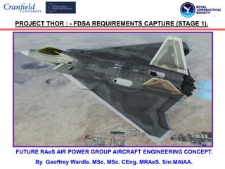
  • 1. FUTURE RAeS AIR POWER GROUP AIRCRAFT ENGINEERING CONCEPT. By Geoffrey Wardle. MSc. MSc. CEng. MRAeS. Snr.MAIAA. PROJECT THOR : - FDSA REQUIREMENTS CAPTURE (STAGE 1).
  • 2. This is the design concept for a paper I intend to submit to the RAeS Air Power Group in 2022, this research is to cover the first, three stages of the concept design process: - 1) Requirements capture: - This presentation. 2) Design trade studies: - 3) Preliminary design proposal and structural layout: - The American Institute of Aeronautics and Astronautics (AIAA) sponsors a collegiate design competitions (reference 1), which was used as the requirements foundation for a Future Deep Strike Aircraft. The request for proposals (RFP) for the 2001-2002 team university aircraft design competition outlined a requirement for a stealth supersonic interdictor to replace the subsonic F- 117, the FB-111, F-15E and even the B-1B and to augment the ATB (now the Northrop B-21 Raider) additions and modifications to this RFP have been made to modernize it as RFP - 997. This study will use public source material which will be referenced to formulate the FDSA proposal response and will not contain any ITAR or IP material it is an academic tool for use by such institutions as the USAFA and the RAFC Cranwell. I will use USAFA AeroDYNAMIC JD3™ MDO toolset for concept performance analysis, and used Catia V5.R21 surface, solid (CFC and Metallic structural layout and component design), and kinematics, and FEA using Nastran 2000, through to preliminary design to the Cranfield Aerospace Solutions Design Manual CIT/COA/AA0/1 Issue 3 (29/07/99), producing a modular airframe capable of modification from two manned crew to an unmanned type, and designed for autonomous assembly, and in service maintenance. 2 Introduction to the FDSA (Thor.) Concept and Preliminary Design Study.
  • 3. Chart 1:- Weapons System Engineering Concept strategy used in this project. This design study will employ the Weapons System Engineering Concept strategy to develop this study within the USAF structured capabilities - based assessment methodology taking the study from concept to (theoretical) IOC. This will enable evaluation by the USAFA for possible use as an academic study, below is the Weapons Systems Engineer visualisation V-model to be applied. 3 Develop Systems Concept, Understand User Requirements and Validation plan. Develop Systems Performance Specifications and Systems Validation plan. Expand Performance Specifications into CI “Design - to” Specifications and CI Validation plan. Evolve “Design -to” Specifications into “Build - to” Documentation and Inspection plan. Fabricate, Assemble and Code to “Design - to” Documentation. Inspect “Build - to” Documentation. Assemble CI’s and Preform CI Verification to CI “Design - to” Specification. Integrate Systems and Perform Systems Verification to Performance Specifications . Demonstrate and Validate Systems to User Validation plan. Time
  • 4.  The purpose of this study is to give lectures of military Airforce institutions such as the USAFA and RAFC Cranwell a case study of a hypothetical concept Future Deep Strike Aircraft (FDSA) to use in the teaching of the application of systems engineering principles. The FDSA is designed for the Penetrating Counter Air / Penetrating Electronic Attack missions, against a future great power adversary, with a proposed in Initial Operational Capability of 2045. Although the actual project is hypothetical it is based on current real world threats, technologies, and emerging capabilities.  The systems engineering process used in today‟s complex systems - of - systems projects such as F-35 and F/A-22 projects is a process matured and founded on the principles of weapons systems development in the past. The examples of systems engineering used on other programs, past and present provide a wealth of lessons learnt which can be used and applied to today‟s projects, and this was the thinking behind the FDSA project design study, and the historic case studies produced by the Centre for Systems Engineering at the Air Force Institute of Technology (AFIT/SY) Wright - Patterson AFB Ohio, USA.  The purpose of developing this detailed project case study is to support the teaching of the application of systems engineering principles, to military aircraft design projects, and to develop a wider understanding of military aircraft concept design. This will facilitate learning by emphasizing to the student the vital need to consider the long - term consequences of weapons systems engineering and programme decisions on project success. The FDSA WSC project when used with existing AFITY/SY case studies will enable the student to apply learnt methodologies, tools, processes and tools to determine the outcome of alternatives at the project / systems level. 4 Learning objectives of the FDSA (Thor.) Concept and Preliminary Design Study.
  • 5.  Weapons Systems Engineering is the technical engineering and technical management process that is focused on delivering and sustaining robust high - quality, affordable, high - capability weapons that meet the needs of the warfighter the USAF in this case (not to be confused with an individual system on a platform e.g. fuel, or electrical). The process must operate effectively with desired mission - level capabilities, established system - level requirements allocate these down to the lowest level of the design, and ensure validation and verification of performance meeting cost and schedule constraints. The weapons systems engineering process changes as the project progresses from one phase to the next (see chart 1), as do the tools and procedures applied.  The Future Deep Strike Aircraft Weapons System Concept project will in addition to system engineering will focus on using skills from multiple professions and engineering disciplines (e.g. concept design, structures, electromagnetics, propulsion, and avionics, etc.) and collecting, assessing, and integrating varied functional data will be emphasized. Overall the student will be provided with a near - term real - world based project to apply weapons system concept engineering and make recommendations in an attempt to balance cost, capability, schedule and performance criteria.  The Key learning principles for this study are presented on slides 6 and 7. 5 Learning objectives of the FDSA (Thor.) Concept and Preliminary Design Study.
  • 6. 1) LP.1 - Requirements definition and management: - Are the requirements for the FDSA clear and realistic, would they be easy to manage and validate? 2) LP.2 - Weapon Systems Architecture and design Trade Off’s: - Is there adequate scope in the design trade studies in order to achieve in the FDSA a Weapons System Concept that will be balanced for performance, mission effectiveness, survivability, and cost, at the Technology Readiness Levels (TRL) and Manufacturing Readiness Levels (MRL) required with the attendant risk to schedule impacts? 3) LP.3 - Communications and Systems Management : - Has there been full open and detailed communication between the Air Staff, DoD, AFRC and the contractors design and engineering teams? Have future maintainers and operational level engineering staff been involved at the initial requirements and concept stages? Have all issues been raised and dealt with in a way that is acceptable to all parties. Has there been sound application of systems engineering principles by the Weapon System Program Office? 4) LP.4 - Validation and Verification: - The FDSA like any complex weapon systems development program which provides new war-fighting capability, has areas of risk or deficiency that comes to light during RDT&E, even if it was perceived low risk in the concept design stage. Have all of the major program risks been identified before moving to the preliminary design stage for the FDSA? Have all of the testing requirements for the airframe / powerplants / and systems been identified fully scoped out with planned resourcing and costing? 6 Key learning principles of the FDSA (Thor.) Concept Study.
  • 7. 5) LP.5 - Risk Planning and Management: - The intention is that the FDSA program is structured so that risks affecting the viability of the weapons system concept are identified at contract award and are structured as Work Breakdown Studies (going deeper than design trade studies in evaluating all relevant issues of the proposed engineering solutions), these feed into the Integrated Project Teams consisting of design, structures, manufacturing, logistics, maintainers, weights, cost, and QA engineers. These IPT‟s will interact with USAF/Systems Project Office specialists to evaluate solutions and assess performance trade-off‟s against schedule costs, and risk. The initial risks are those “normal” risks associated with a large complex weapons system development as well as new technology and processes necessary to mature the program to low to medium risk at PDR. The risk closure process will continue throughout the FDSA development and identify new risks and continuously identify new risk closure plans. These plans will show all design, analysis, tests, tooling, and other tasks necessary to close the identified risk and will be maintained as part of the normal design / program reporting activity. The student will learn how to assess these plans and if they are developed enough to lower the risks to an acceptable level of technical maturity for PDR. Upon completion of this case study the student will have a wide appreciation of what will be required for the planning and design and development of a near future Combat Air Weapon System for the USAF. 7 Key learning principles of the FDSA (Thor.) Concept Study.
  • 8. FDSA PROJECT THOR STAGE 1 CONTENTS. 1) Request For Proposals - 997 Threat Analysis. Slides 9 - 15 2) Potential great and medium power adversaries A2/AD capabilities. Slides 16 - 28 3) Assumptions Made in Defining the FDSA Requirements. Slides 29 - 30 4) FDSA Missions / Key Attributes and Requirements. Slides 30 - 73 5) FDSA Operational Requirements Capture and Analysis Slides 74 - 80 6) Type of Design Selection, Special type: Modification: or New. Slides 81 - 82 7) Key Design Requirement Evaluation. Slides 83 - 92 8) Concepts and Initial Sizing and project future Stages. Slides 93 - 96 9) Reference works. Slides 97 - 99 8
  • 9. The United States air and naval Combat Air Forces have provided an asymmetric advantage over its enemies, from the late 1930‟s the United States has been the only nation to create and sustain an operational fleet of combat aircraft capable of striking targets anywhere on the globe. Over the last decade of the 20th Century and the first two decades of the 21st Century combat aircraft equipped with precision - guided munitions, first and second generation stealth technology, advanced sensors, and other mission systems have played pivotal roles during conflicts in the Balkans, the Middle East, and South Asia. In the 2020‟s and beyond the U.S. Department of Defence is at a turning point after a decade of counterinsurgency warfare, today the US and other major Western nations face the challenge of to a return to Great Power Competition. America‟s focus on counterinsurgency and non - state terrorists has given China, Iran, North Korea, and Russia as well as other competitors the action space to develop anti - access / area denial (A2/AD)² that could threaten U.S. access to areas of vital interest. The proliferation of long range ballistic, and advanced cruise missiles ( charts 1- 4), anti - satellite weapons, and cyber threats as Integrated Aerospace Defence Systems (IADS) has and will constrict and diminish the U.S. military's ability to respond to international crisis in a timely manner and negate the freedom of action previously employed. In terms of future air campaigns beyond 2040 these A2/AD capabilities impact on the USAF in that air dominance in future wars cannot be taken for granted, Command and Control networks may not be secure, in theatre air bases will be venerable to enemy attack, and non stealthy intelligence, surveillance, and reconnaissance assets (ISR) and strike aircraft manned or unmanned will suffer unacceptable losses penetrating contested airspace. 9 Part 1: - Request For Proposals RFP - 997 Threat Analysis.
  • 10. The Return of Great Power Competition (the New Cold War):- 29 years since the end of the first Cold War 01 January 1991, the World is moving inexorably towards a new Great Power Competition which has every indication of not ending as favourably for the West as the last one, without the West being able to hold the adversaries most important targets at risk. Russia‟s aggression against Eastern Europe‟s frontline states (Georgia, Ukraine, etc.) and continued probing of western air defences coupled with a massive build up of conventional and nuclear forces do not indicate a 1990‟s style coexistence. Also China‟s expansion in East and South China Seas coupled with massive military expansion and development of hither too western advanced military technologies, signals a return to Great Power Competition. Russia and China are both manifestly intent on establishing regional and international in their favour by undermining Western influence in their respective zones of interest. This will present major challenges to the security of the United States and its regional allies but also the stability of the international system by limiting the ability of the US and its allies to intervene in regional crisis by:-  Restricting or denying the US access to forward bases through either political coercion or the aggressive threat of precise missile and or air strikes:  Limiting freedom of movement and manoeuvre for US Navy surface vessel task forces, and carrier battle groups:  Degrading US C4ISR networks with kinetic and non kinetic weapons:  Hobbling US power projection by attacking “soft” logistics targets:  Limiting the effectiveness of US precision strikes. 10 Request For Proposals RFP - 997 Threat Analysis.
  • 11.  Precision Strike effectiveness is being limited by the following means:-  Fielding advanced integrated air defence system (IADS);  Using strategic depth to move potential targets further inland;  Hardening and / or deeply burying potential targets;  Increasing the mobility of key military systems, such as SAM‟s and missile transporter erector launchers (TEL). Not only Russia and China are enacting these policies but North Korea, and Iran are playing their part, see charts 1 through 8 illustrating threats to in theatre basing of precision strike assets. In continental Europe a revisionist Russia is determine to reform the former Soviet Union and regain Russia‟s great power status through domination of former Soviet and Warsaw Pact states either by coercion, or invasion. Thus stopping these states from joining NATO and indeed seeking to discredit NATO‟s in that it would not be able to deter such Russia actions or defend such nations from aggression. The perceived requirement of Russia to have a wall of protective “sacrificial” states is not new and dates back to the post World War 2 division of Europe by the allied nations, however since the collapse of the former Soviet Union on 26th December 1991, the perception in the West was that these buffer states would be allowed to choose there own path forward, however this appears to be no longer the case. In fact in the past 10 years there has been a disturbing increase in both the intensity of what Russia perceives to be an infiltration in to its territory and it willingness to use military, economic, cyber, and other elements of its national power to achieve the objective of reforming its buffer states. 11 Request For Proposals RFP - 997 Threat Analysis.
  • 12. Russia‟s annexation of Crimea and subsequent invasion of eastern Ukraine has undermine the normal political foundations of eastern Europe and has put the former Eastern Block nations on notice that if Russia‟s requirements are not met there will be military consequences, and precipitated the most serious European crisis since the Balkans war of the 1990‟s. NATO‟s defence posture and by extension the United States is rapidly losing credibility and the capability to deter a new Russia intent on using military force as the ultimate means to achieve its national objectives, and is currently in a vast and on going defence modernisation program, overmatching NATO‟s frontline states. The Chinese are also engaged in a extensive military rearmament program with the apparent goal of extending their power and influence even further beyond their shores destabilizing the military balance in the region which has enabled unparalleled peace and prosperity in the far east for the past thirty years. China see military force as an arm of diplomacy not as an alternative, examples of this can be found the claims on potential oil and gas in the South China Sea (see figure 1), the continued clashes with Vietnam since the annexation of the Paracel Islands,(now a base for PLAAF combat aircraft with a 2,500m runway), in Hong Kong‟s assimilation back into main land Chinese control, the stance China has taken on the disputed Spratly Islands with Vietnam (China has engaged in a shooting battle that sank two Vietnamese warships killing 70) , and the very real risk of China‟s assimilation of Taiwan by military means. China would argue that its expansion is necessary to protect its sea lanes from the west passing through the vital Strait of Malacca (see figure 2) which for example sees 80% of China‟s imports of crude oil. Troubles within the Exclusive Economic Zone both in the South China Sea and the East China Sea centre on island disputes and their potential oil and gas reserves. 12 Request For Proposals RFP - 997 Threat Analysis.
  • 13. 13 Taiwan Philippines Malaysia Vietnam China Potential oil and gas fields in the South China Sea and countries maritime claims of ownership. PLAAF airbase on Woody Island one of the Paracel Islands in the South China Sea for Su 27 / Su 35 and J-20 Combat Aircraft. Figure 1: - China‟s key fuel admissions in the South China Sea region. *Reference: - 2 *Reference: - 2
  • 14. 14 Figure 2: - China‟s need to control sea lanes in the South China Sea region. *Reference: - 2
  • 15. All countries around the South China Sea perceive it as an important source income currently from fishing rights, but they are all eager to claim and explore its potential oil and natural gas reserves. As can be seen from figure 1 several states have overlapping claims over the South China Sea and disagreements about the Exclusive Economic Zones (EEZ) have lead to several states occupying islands in the area without explicitly laying legal claim to the islands in question, hoping that a de facto land grab will become legitimate over the duration of the occupation. This has raised tensions in the region when surprise invasions occur, leading to naval battles, political and diplomatic protests, and seizure of ships and arrest crews entering these disputed areas. The rewards of these actions are high for example the U.S. Geological survey estimates the total confirmed discovered and potential undiscovered resources to 28bn barrels of oil, Chinese estimates for the same area however are much higher in the order of 105bn to 213bn barrels of oil. Although most of the current finds in the South China Sea are gas deposits and China estimates there are 900 trillion cubic feet of gas in this region. The two most disputed island groups are the Paracel Islands, and the Spratly Islands as shown in figure one. The East China Sea is also an area of 1.2 million Km³ and has disputed large oil and natural gas deposits, and here the main parties are Japan and China, Taiwan also has claims but is not using force, and as Japan has virtually no domestic oil or gas reserves these disputed zones are of great national importance. The East China Sea disagreement has two route causes (1): - all parties disagree on the determination of Exclusive Economic Zones in the East China Sea, (2): - China, Japan and Taiwan disagree on the ownership of the Diaoyutai / Senkaku Islands which are believed to have large oil and natural gas deposits, with the disputes resulting in mirrored actions to those in the South China Sea. 15 Request For Proposals RFP - 997 Threat Analysis.
  • 16. Part 2: - Potential great and medium power adversaries A2/AD capabilities.  Chart 2: - North Korea‟s ballistic missile program is one of the most rapidly developing threats to global security at the current and 2020-2040 timeframe. In recent years, an unprecedented pace of missile testing has included new and longer range missiles, sea-launches and the orbiting of satellites. The most notable of these advances is North Korea‟s development of a new Intercontinental Ballistic Missile, the Hansong - 14, which can possibly reach the west coast of the continental United States. To hold at risk targets in North Korea from bases in Guam combat radius of 2000nm hence a range of 4000nm on internal fuel.  Chart 3: - Iran possesses the largest and most diverse missile arsenal in the Middle East, with thousands of short and medium - range ballistic and cruise missiles capable of striking as far as Israel and South East Europe. Missiles have become a central tool of Iranian power projection and anti-access / area - denial A2/AD capabilities in the face of US and Gulf Cooperation Council Air and Naval power in the region. To hold targets at risk in Iran a combat radius and persistence of 1500 nm is required hence a range in the order of 3500nm on internal fuel.  Chart 4: - Russia boasts the widest inventory of ballistic and cruise missiles in the World the majority of which are on mobile launchers. With significant modernisation yielding new heavy ICBM‟s and ground - launched cruise missiles in direct violation of the Intermediate Range Nuclear Force INF treaty (which saw the USAF withdraw the Tomahawk BGM-109, and at that time the USSR withdrew the SS-20 IRBM). Moscow‟s strategic rocket forces perform a verity of missions from anti access / area denial A2/AD in local conflicts to the delivery of strategic nuclear weapons. To hold key Russian targets at risk a combat radius in the order of 2000nm and a range of 4000nm on internal fuel from bases in western Europe and the UK. 16
  • 17. 17 Chart 2: - PR North Korea‟s localized basing denial capabilities (missiles). *Reference: - 3
  • 18. 18 Chart 3: - The Iranian localized basing denial capabilities (missiles). MRBM Range (km) Shahab-3 Shahab-3A Shahab-3B Shahab-4 1,300-1,500 1,500-1,800 2,000-2,500 2,000 Ghadr-1 1,950 Sejil/Sejil-2/Ashoura Sejil-3 2,000 4,000 IRBM Musudan (BM-25) 4,000 SRBM Range (km) Scud-B/ Hwasong-5 300 Tondar-69 150 Fateh-110 Fateh-110 2nd gen Fateh-110 3rd gen Fateh-110-D1 Khalij Fars ASBM Fateh-313 Hormuz-1 Hormuz-2 ASBM 200 250 300 300 300 500 300 300 Shahab-1 Shahab-2 300 500 Qiam-1 800 Ghader Shahab IRAN’S BALLISTIC MISSILES *References: - 3
  • 19. 19 Chart 4: - Russia's localized basing denial capabilities (missiles). *Reference: - 3
  • 20. 20 Chart 5: - PR China‟s localized basing denial capabilities (missiles). *Reference: - 3
  • 21.  Chart 5: - China has the most active and diverse ballistic missile development program in the World, upgrading its missile forces in number, type and capability. China is modernizing its ICBM‟s developing independently targetable re-entry vehicles and manoeuvring boost - glide vehicles, and has begun deploying a new fleet of ballistic missile submarines. Short and medium range cruise and ballistic missiles form a critical part of its regional anti-access and aria denial A2/AD efforts. Again to hold targets at risk in China the range requirements would be similar to those of Russia namely a combat radius of 2000nm and a range 4000nm on internal fuel from Guam. The Future Deep Strike Aircraft will have to operate in areas covered by advanced 2A/AD systems that Russia, China, and others have created to contest US air superiority and increase the freedom of manoeuvre for their own air, land and maritime forces charts 6 and 7 illustrate the current 2A/AD situation in Europe fielded by Russia, and in the South China Sea fielded by China, as examples. These systems are more than a network of surface to air missile launchers, an IADS 2A/AD is a composite of air and missile defences that includes active and passive sensors, weapons, battle management networks, and associated infrastructure, and operators. Although they vary in general configuration and effectiveness the most effective IADS create overlapping networks of air-to air, surface to air threats which are highly mobile and use passive sensors, camouflage, EW/ECM, and deception to minimise detection and possible engagement. Therefore in these treat environments future combat aircraft must be able to counter multiple domain threats of advanced IADS 2A/AD systems. 21 Potential great and medium power adversaries A2/AD capabilities.
  • 22. 22 Chart 6: - Threats to US Combat Air Force from Russian 2A/AD in Europe. *Reference: - 4
  • 23. 23 Chart 7: - Threats to US Combat Air Force from Chinese 2A/AD in SCS. *Reference: - 4
  • 24. Advanced Integrated Air Defence Systems: - Russia and China are improving the sophistication, coverage, and density of their IADS, for example once the 40N6 long range missiles are fully integrated with the S - 400 Surface to Air Missile system it will possibly have a range of up to 250 miles (400km) against 4th generation fighters, fighter bombers, and earlier generation heavy bombers, and even purports to have Anti Ballistic Missile (ABM) capabilities against re-entry vehicles travelling at Mach 16. Where as the 40N6 missile is designed to hold high value targets at risk over long ranges, the S-400 system can launch a range of different Surface to Air Missiles which includes the medium range 48N6 and the short range 9M96 families to engage agile fighter aircraft and cruise missiles (reference 5), figures 3 and 4 show the fire units and command and control units of a typical S-400 battalion. Coupled with the Grave Stone 92N6 engagement and fire control radar a single S-400 battery could engage ten targets simultaneously aiming two missiles per target to increase the kill probability. SAM systems of this type have built in redundancy form component units of the overlapping layered IADS. The ground based component of the Russian and Chinese layered IADS contain multiple weapons systems that are complementary, to balance out the capabilities of each system, and covering a wide verity of threats. These can be controlled by a single battle management system that prioritises threats, de-conflicts potential target engagements and calculates optimal firing solutions (reference 5). The shorter range SAM systems supplement the high cost and hence limited inventory of strategic very long range SAM‟s enabling them to target JSTAR, and Tanker assets. 24 Potential great and medium power adversaries A2/AD capabilities.
  • 25. 25 Grave Stone Engagement and Fire Control Radar. S-400 Defence Battery Up to 12 Launchers, each with 4 missiles. S-400 Launcher unit with 4 missiles. S-400 Launcher Short and Medium range missiles. Figure 3: - Fire units and missile types of the S-400 SAM Battalion.
  • 26. 26 Figure 4: - Command and control units of the S-400 SAM Battalion. Mobile all - altitude acquisition radar. Mobile command post on Ural-532301. Big Bird acquisition and battle management radar. Command and Control equipment. Optional equipment. 40V6MR Mobile mast system no to scale.
  • 27. The Russians employ tactical SAM‟s to support their land manoeuvre forces and fill gaps in the larger air defence network. Russian and Chinese A2/AD IADS systems are also more resilient to counter - strikes than the comparable systems the US or NATO air forces have had to contend with in the First Gulf War or the Kosovo conflict. Russian S-400 battalions usually deploy with Pantsir self propelled AAA, and missile systems that are optimised to engage JDAM‟s, JSOW, and Anti Radiation Missiles (e.g. ALARM), Unmanned Air Systems, and Conventional Air Launched Curies Missiles, and other threats. However to answer this a High Power Microwave pulse from the stealth Phantom(PEA) ASHPMM (covered below). The Russia and Chinese systems are highly mobile allowing them to relocate to new zones where needed as the battlespace evolves. The critical systems of an S-400 battalion are shown in figures 3 and 4, and include the missile transporter erector launchers (TEL‟s), radar units Grave Stone, and Big Bird, as well as support vehicles, all of which can be relocated in minutes enabling a “shoot and scoot” philosophy to be adopted in operational deployment. This mobility reduces the battalions exposure time to counter - strike, especially to USAF or NATO weapons with longer flight times. The importance of flight time and distance from the target in countering the Russian and Chinese IADS systems mobility is illustrated in figure 5, and in fact for a missile launched 800nm from at a S-400 TLE would need to fly faster than Mach14 point to point with no manoeuvring to reach it before it could relocate. In order to hold targets at risk and to penetrate A2/AD networks of potential great and medium powers there is an urgent need to rebalance the USAF combat air capability with long range deep strike aircraft that can overcome the great and medium powers tyranny of distance illustrated in charts 2 through 7, striking quickly over the horizon with less reliance on FOB‟s and tanker support. 27 Potential great and medium power adversaries A2/AD capabilities.
  • 28. 28 Figure 5: - Importance of proximity to target and weapons speed. Low Subsonic SDB High Subsonic JASSM Mach 2 Supersonic AARGM Mach 5 Hypersonic Stand off distance where the flight time of a Mach 5 weapon exceeds 5min S300 SAM can relocate in 5min (n miles) (min)
  • 29. The basing and range factors were are based on the assumption of stealth or protected tanker support being available, for all practical operational scenarios outside total nuclear war, the fallowing assumptions will be made for this requirement: - 1) Tanker support is available: 2) The tanker force can operate within 500nm of the aggressors coastal defence envelope: 3) Next Gen Tankers KC-Y / KC-Z to replace the KC-10‟s and KC-135R will have stealth characteristics will be protected by the LALDS for self protection this will be the first steps against the aggressors A2/AD system: 4) Development of a new AHSAM / ASHPMM (Phantom) (WSC-87930) with a range of 1000nm and carry either a Ultra - High Power Microwave generator, or Multiple Smart Submunition‟s, for use against large fixed targets e.g. Airfields, BMC², IADS, and this will impart additional range to the FDSA which will carry 2 or 4 internally over its combat radius in place of normal weapons configuration: 5) The FDSA will have a large internal weapons bay capable of carrying current and future weapons including Phantom(PCA)/(PEA) and the AALBM (Meteor Storm) (WSC-95401), and will be equipped with modular multi weapon standardised interfaces: 6) Propulsion will be from two ADVENT derivative engines each of 45,000lb dry thrust and 60,000lb thrust with afterburner, with 2-d thrust vectoring nozzles, which yield 40% greater range, 60% greater loiter time, and meet NATO airfield requirements: 7) The FDSA will be provided with a form of ALDS effective against SAM missile threats and AAM. 29 Part 3: - Assumptions made for defining the FDSA mission requirements.
  • 30. The primary missions that the Future Deep Strike Aircraft must be capable of completing are described below and through the developments in PGM see figure 6, one aircraft will be tasked with multiple targets Phantom and Meteor Storm details beyond OML / dimensions held in WSC‟s. a) Penetrating Electronic Attack (PEA) ASHPMM, precision strike in all weathers day / night against deployed IADS assets over a combat radius of 2,500nm on internal fuel (from the last tanker contact). These will include S-400 battalions and command and control equipment using the Phantom(PEA) ASHPMM this will afford an additional 1,000nm range and is carried internally. b) Penetrating Counter Air (PCA), precision strike in all weathers day / night against enemy air bases using AALBM, over a combat radius of 2500nm on internal fuel, using Meteor Storm and or Phantom(PCA) ASHAM, which will afford an additional 1,000nm range to target and is carried internally. c) Loyal Wingman Control and UAS mission tasking platform. d) Penetrating Strike and Reconnaissance missions against fixed and mobile tactical nuclear weapons sites, air - to - air support and self defence (see figure 7). These key requirements for the FDSA must be met to accomplish the above missions. 1) Advanced Outer Mould Line Designs:- The Outer Mould Lines (OML) or external shape of the aircraft accounts for the bulk of the airframe RCS signature, and planform alignment is used on Fifth Generation fighter aircraft namely F-22A Raptor, F-35 Lightning 2 family, and Third / Fourth Generation bomber aircraft the B-2A, and the B-21 Raider this has to be incorporated from the concept of the design. 30 Part 4: - Future Deep Strike Aircraft Mission and Key Attributes Required.
  • 31. 31 Figure 6: - From sorties per target to targets per sortie the rise of PGM‟s. Time. USAF Today 1 bomber: 80 PGMs: Up to 80 targets. Targets per Sortie. More sorties per target. More targets per sortie . Ratio = 1 to 1 USAAF Germany 1944 1,000 bombers: 9,000 weapons: 1 target. USAF Vietnam 1970 30 fighter bombers: 176 unguided weapons: 1 target. USAF Iraq 1991 1 fighter bomber: 2 laser guided weapons: 1 or 2 targets. USAF Iraq 2003 1 bomber: 16 PGMs: Up to 16 targets. Smaller air delivered munitions. GPS guided munitions. Laser guided munitions.
  • 32. 2) All - aspect broadband signature control: - All -aspect signature control has become increasingly important for the survivability of a penetrating aircraft as the FDSA, and LRSB, due to the advances in computing power for data fusion and radar systems layout such as Bistatic and Multistatic (multiple passive receivers). The adoption of angled ruddervators is recommended, instead of the four part tail designs of the F-22A and the F-35, canard layouts are not recommended as they have proven to be less stealthy. The adoption of vectored nozzles either 2-d as per the F-22A or multi axial is recommended and obscuring intake ducts will be essential to meet these requirements. Advanced structural materials science, processing manufacture, and assembly technologies should produce materials with reduced and controllable emissivity properties TRL = 8 and MRL = 7 see chart 8 and table 2. 3) LPI/LPD communications and data links: - Advances in the sensitivity and capability of the potential adversaries passive sensors has made high -power omnidirectional radio emissions and datalinks a significant vulnerability for PEA / PCA platforms like the proposed FDSA that are designed to penetrate contested airspace. Therefore the FDSA must have Low Probability of Intercept / Low Probability of Detection (LPI / LPD) communications systems that can be directional focused and have low-power and narrow beamwidths to reduce detection risks. 4) Advanced sensor suites: - Platforms equipped with LPI / LPD data communications links will still encounter some localized denied or degraded areas of the battlespace, when in battle with a great power adversary, therefore the FDSA will require an organic capability to actively, and passively detect, track and engage mobile and static targets. The possible sensors would be multi-spectral, multi-phenomenology sensor suites with extensive ranges to sense and counter threats and avoid detection, by these threats. 32 Future Deep Strike Aircraft Mission and Key Attributes Required.
  • 33. 5) Multi - domain interoperability: - To fully utilise the data collected by the FDSA‟s advanced sensor suite, the platform must have the ability to share this data across all mission platforms and assets in the strike package and back to the wider Combat Air Force, and coalition platforms. This will require secure distributed, all - domain, self - healing network to enable shared situational awareness, battlespace management, and command and control. This extent of interoperability will be an enabler for the Combat Air Force to conduct effects based strikes in multiple domains at a very high operational tempo that great power adversaries can neither counter or match. 6) Penetrating Electronic Attack / Penetrating Counter Air (PEA/PCA) Specific FDSA Requirements: - Prime weapons bays of sufficient size to accommodate either: - two Phantom ASHPMM for the PEA mission, or two AALBM, for the PCA mission, these will constitute the primary SEAD / DAED mission load - outs, additional interface ability is required in this bay for multiple Advanced Long Range Air - to - Air Missiles as an alternative load - outs on rotary launchers. Sub - weapons bays as in the case of the F-22 for Small Advanced Capability Missiles (SACM) to counter Air to Air threats (figure 7) will be required. Incorporation of two or more DEW turrets is required with upper and lower hemisphere coverage arcs, these are to be Solid State derivatives of the LADS. Trade Studies of real world Range / Payload / Speed with ADVENT engines are mandatory from the contractors for down selection. 7) All concepts for the FDSA: - To yield the greatest performance: - Range, Speed, Signature, capacity, all concepts of will use two of the ADVENT engines figure 10, outlined in this RFP detailed in the supporting documentation, and be compatible with High Energy Bio Fuels, to yield cruise altitude of 50,000ft and a max altitude of 65,000ft. 33 Future Deep Strike Aircraft Mission and Key Attributes Required.
  • 34. 34 Figure 7: - Air borne threats to the Future Deep Strike Aircraft Missions. J-20 PLAAF T-50 / Su-57 Russian AF SU - 35S Russian AF
  • 35. Maximum speed 2,440km/h (1,320mph) Mach 2 at altitude 2,440km/h (1,320mph) Mach 2 at altitude or 1,710km/h (1,060mph) Mach 1.6 at sea level. 2,400km/h (1500mph) Mach 2.25 at altitude or 1,400km/h (870mph) at sea level. Cruise speed Unpublished Unpublished 1,250km/h (780mph) Mach 1.1+ supercruise at medium altitude. Combat range 2,000km (1,200miles) assume subsonic. 3,500km (2,175miles) subsonic / 1,500km (930miles) supersonic. 1,600km (900miles / 860nmiles) Ferry range 6,000km (3,700miles) 5,500km (3,420miles) with one refuelling. 4,500km (2,800miles / 2,400nmiles) g - limit +9/-3 +9/-3 +9/-3 Rate of Climb 304m/s (59,800ft / min) Unpublished 280m/s (55,000ft / min) Service ceiling 20,000m (66,000ft) 20,000m (66,000ft) 18,000m (59,000ft) 35 Table 1: - Major air borne threat platforms performance data.
  • 36. 8) FDSA Basing Operational Requirements: - The FDSA must be capable of „all-weather‟ operations from advanced NATO and other bases. Existing aircraft shelter dimensions may impose configurational constraints on the aircraft i.e. length <98ft (30m) and span <65ft (20m), but are only to be adhered to if these constraints do not inhibit performance, payload, or mission effectiveness. Aircraft servicing and maintenance at austere operational bases demand minimum support equipment and technical support. Easy access to primary system components must be provided, these should be line repairable or replicable. Low observable coatings and structure should be highly durable and easily repairable in austere environments TRL 8 (Technology Readiness Level) and MRL 7 (Manufacturing Readiness Level). See charts 8 and 9 and table 2. 9) Closed - loop: - Static and dynamic stability and handling flight characteristics must meet established military requirements MIL-F-8785B, subsonic longitudinal static margins to be no grater than +10% and no less than -30%. Hence a digital flight control system will be necessary for a longitudinal unstable aircraft configuration, a triple redundant fly by light fibre optic system is desired. All systems must be protected against EMP / EM / and hostile damage, and must be at a TRL 8 (Technology Readiness Level) and MRL 8 (Manufacturing Readiness Level). See charts 8 and 10 and table 2. 10) Structural design limits: - Design limit load factors of +7g to -3g (aircraft clean and with 50% internal fuel) are required. An ultimate design factor of 1.5 is to be applied. The structure must be capable of withstanding a dynamic pressure (q) of 2133lb/sq.ft, (i.e. equivalent to (q) at 800kt) and be durable and damage tolerant. 36 Future Deep Strike Aircraft Mission and Key Attributes Required.
  • 37. Chart 8 :- DoD Technology Readiness Levels and Manufacturing Readiness Levels. 37 MRL1 Basic Manufacturing Implications Identified. MRL6 Capability to produce a prototype system or subsystem in a production relevant environment. MRL2 Manufacturing Concept Identified. MRL7 Capability to produce components, subsystems, and systems in a production representative environment. MRL3 Manufacturing proof of concept developed. MRL8 Pilot line capability demonstrated, ready to start Low Rate Initial Production (LRIP). MRL4 Capability to produce component in a lab environment. MRL9 LRIP Demonstrated capability for Full Rate Production (FRP) in place. MRL5 Capability to produce component in a production relevant environment. MRL10 Full Rate Production (FRP) demonstrated and lean production practices in place. Manufacturing Readiness Levels (MRL).
  • 38. 38 Table 2 :- DoD GAO-20-48G TRL‟s applied to the Future Deep Strike Aircraft. TRL. Definition. Description. 1 Basic principles observed and recorded. Lowest level of technology readiness. Start of translation from scientific research into applied research and development (R&D). E.g. paper studies of a technologies basic properties. 2 Technology concept and / or applications formulated. Invention begins, once the principles have been observed, practical applications can be identified by limited analytical studies. Although at this stage there is no detailed data to support these theoretical applications. 3 Analytical and experimental function and / or character proof of concept. Active R&D, analytical studies and laboratory tests to physically validate the analytical predictions of separate elements of the technology. Examples would be components that are not yet integrated or truly representative. 4 Concept and / or breadboard validation in a laboratory environment. Basic technology component integration to establish that they will work together. This is “low - fidelity” compared to the final system. Examples are the integration of “ad-hoc” hardware in the laboratory. 5 Concept and / or breadboard validation in a relevant environment. Fidelity of breadboard technology significantly increased. Basic technology components are integrated with realistic supporting elements so that they can be tested in simulated environments. Examples are high-fidelity laboratory component integration. 6 System / subsystem model or prototype demonstrated in relevant environment. Representative model or prototype system which is beyond that of TRL 5 is tested in a relevant environment. Examples include testing the prototype in high fidelity laboratory environment or testing in a simulated operational environment. 7 System prototype demonstrated in an operational environment. Prototype near or at planned operational system and is a major step up from TRL 6 by requiring the demonstration of the actual system prototype in an operational environment (e.g. in an aircraft, vehicle, or in space). 8 Actual system complete and qualified through test and demonstration. Technology has been proven to work in its final form and under expected mission conditions this is in almost all cases this TRL is the end of R&D, and starts final DT&E against design specifications. 9 Actual system mission proven. Actual application of the technology in its final form in Operational Test & Evaluation OT&E in operational conditions / real world mission environments.
  • 39. 11) Fuel tanks: - All fuel tanks must be self - sealing and internal fuel tanks must have an OBBEGS nitrogen wash, fuel vapour innerting system installed. 12) Aircrew: - The aircraft must accommodate two aircrew the pilot commander and a pilot mission specialist, in an emergency if the commander pilot become incapacitated the pilot mission specialist should be able of taking control of the aircraft for single pilot operations to complete the mission. Additional autonomous systems should be available to return the aircraft to a safe recovery if both crew are incapacitated. For the long range 15+hr missions envisaged and illustrated in figure 8, and outlined in table 3, pilot workload must be reduced by suitable design and specification of flight control systems incorporating human factors, and weapons delivery systems. Crew safety systems must be effective in all flight modes. 13) Manoeuvring targets: - In addition to the high altitude, supercruising mission shown in figure 8 and described in table 3 the following manoeuvring targets must be met N.B. Specific Excess Power SEP is defined as Ps where Ps = [(T-D)/W]V (where weight W =M*g).  SEP(1g) military thrust (dry), 1.6 M at 50,000ft = 0ft/s.  SEP(1g) maximum thrust (wet), 1.6 M at 50,000ft = 200ft/s.  SEP(2g) maximum thrust (wet), 1.6 M at 50,000ft =0ft/s.  Maximum instantaneous turn rate, 0.9 M at 15,000ft = 8.0º/s. All of the above performance criteria are specified at aircraft manoeuvre weight (defined as 50% internal fuel with two ASRAM / two AIM-120, and four 2000lb JDAM‟s). 39 Future Deep Strike Aircraft Mission and Key Attributes Required.
  • 40. Take off Climb to BCA 1 2 3 4 5 6 7 8 9 10 11 12 Super- cruise M1.6 (ingress) Descend Descend Dash in 65,000ft M1.8 Dash out 65,000ft M1.8 Climb Manoeuvre turn and weapon release AALBM Meteor storm or Phantom Land (with reserves) Reduces the threat envelope of SV300 class long range SAM’s Outside the threat envelope of SA-9 type fast short range SAM’s 40 Super- cruise M1.6 (egress) FIGURE 8: - THE FDSA (THOR) CORE PCA WITH AALBM MISSION PROFILE.
  • 41. Segment. Description. Height. Speed. Distance/Duration. 1 - 2 Warm-up, taxi and take-off. Sea – level. NATO 8000ft icy. 2 - 3 Climb to best super – cruise altitude. 3 - 4 Super - cruise to conflict area. Optimum altitude. Mach 1.6 1000 nt miles 4 - 5 Climb to 50,000ft. 5 - 6 Dash to target. 65,000ft Mach 1.8 250 nt miles 6 - 7 Turn and weapon release. 65,000ft Mach 1.8 180 degrees. 7 - 8 Dash out. 65,000ft Mach 1.8 250 nt miles 8 - 9 Descend to super - cruise altitude. 9 - 10 Super - cruise return. Optimum altitude. Mach 1.6 1000 nt miles 10 - 11 Descend to airbase. 11 - 12 Land (with reserve fuel). NATO 8000ft, icy. TABLE 3: - FDSA (Thor) Core Strike Mission Profile. 41
  • 42. 14) Addition / Alternative weapons capabilities: - In addition to the principle weapons capability for the PEA and PCA missions six additional separate weapon capabilities are required for internal carriage therefore a flexible weapons bay is a key requirement;-  Four GBU56 LJDAM + two AIM-120 + two AIM-9M.  Four JASSM-ER + two AIM-120 + two AIM-9M.  Four Mk84/BLU117 JDAM + two AIM-120 + two AIM-9M.  Four AGM-154 JSOW + two AIM-120 + two AIM-9M.  Sixteen 250lb GBU-39/B SDB‟s + two AIM-120 + two AIM-9M.  Incorporation of a High Power Solid State Direct Energy Weapon Module + two AIM-9M. 15) Commonality with Fifth Generation Combat Aircraft:- In order to reduce costs the original FB-22 requirements 2004 envisaged a 60inch plug incorporated into the fuselage of the F- 22A and the inclusion of a second crew station, with a semi - truncated delta wing offering some three times the fuel load of a standard F-22A, twin vertical tails. A 5g manoeuvrability envelope compared to the F-22A‟s 9g was also considered and the deletion of the F-22A thrust vectoring capabilities to reduce cost, the early proposals are shown in figure 9. Since then the new much larger Future Deep Strike Aircraft envisages a maximum of 30% structural commonality with the current F-35 the majority of this being in the Fwd fuselage, avionics and systems will be 90%, a new fuselage to accommodate three weapons bays: - one main and two defence, accommodation for two laser defence turrets, and two AVTE E- 137 engines, and a new delta wing, and twin all moving tails are considered as a baseline. 42 Future Deep Strike Aircraft Mission and Key Attributes Required.
  • 43. 43 Figure 9(a/b): - Baseline FB - 22 proposed configurations 2004. Fig 9(b):- FB-22 Cropped Delta with No Vertical Tails. New Fuselage Extension. Old wing attachment points can still be used. More attachment points in extension and wing chord increased there. One more hard point. Fig 9(a):- FB-22 Diamond Wing with Canted Vertical Tails. Legacy weapons bays SRAAM. Main bay 2000lb JDAM bombs. Side bays 8 SDB bombs on two BRU-61 in a row each side. New fuselage section provides very strong attachment structure for new wing. New wing matted to old and new attachment points. New main landing gear bays aligned with wider fuselage section. . 55º LE wing sweep up to Mach 1.8. 70º LE wing sweep Mach 2.0 dash.
  • 44. 44 Figure 9(c): - Evolutions of FB - 22 proposed configurations 2004. As can be seen from the above graphic the FB-22 went through a number of evolutions before a final configurations shown in figures 9a and 9b were deemed to meet the baseline proposal, and it is expected that the Future Deep Strike Aircraft will be no different. However unlike the FB-22 a new fuselage will be used as standard with different wing configurations and structural commonality will not be with the F-22 but to a level of 25% - 30% with the F-35C, this would constitute the basic forward fuselage with reconfigured intakes to supply two ADVENT engines. Additionally the 2-D vectoring nozzle design for the F-22 will be used to impart tactical manoeuvrability on the FDSA within the loading parameters given in requirements section 13 above but structurally stressed for a maximum load case of 6.6g with a 1.5 factor of safety.
  • 45. 16) Weapons Bay sizing: - In order to meet the weapons internal carriage requirements for the FDSA the following weapons bay provisions need to be incorporated in the airframe proposals;-  Main Flexible Weapons Bay: - Length 375” = 31.25ft (9.525m); Width 114” = 9.50ft (2.89m); Depth 84” = 6.95ft (2.11m).  Side Weapons Bays (each): - Length 130” = 10.185ft (3.3m); Width 42” = 3.50ft (1.07m); Depth 42” = 3.50ft (1.07m).  Prime Weapon Dimensions and Prime Characteristics: -  Phantom(PCA) AHSAM (Advanced Hypersonic Stealth Attack Missile); - Length 25ft (7.6sm); Width 3.5ft (1.07m); Height 3.5ft (1.07m); Weight 4,150lbs (1,882kg); Range 1000nm (1,852km); Multiple smart Submunition's.  Meteor Storm ALBM (Air Launched Ballistic Missile) both HASSM and NS configurations; - Length 28ft (8.53m); Body Diameter 3.0ft; Weight 3,150lbs (1,430kg); Range 1000nm (1,852km) to be launched at 65,000ft ( 19,812m) altitude.  Phantom(PEA) AHPMM (Advanced High Power Microwave Missile); - Length 25ft (7.6sm); Width 3.5ft (1.07m); Height 3.5ft (1.07m); Weight 5,250lbs (1,882kg); Range 1000nm (1,852km); RTG and UHPM 2 x Antennae's. 45 Future Deep Strike Aircraft Mission and Key Attributes Required.
  • 46.  Dimensions and characteristics for alternative weapons carried by the FDSA: -  AIM - 9M;- Length 9ft 5in (2.10m); Body Diameter 5in (12.7cm); Fin Span 2ft 1in (0.64m); Weight 191lbs (86.64kg); Cruising Speed 2.0 Mach; Range 10miles 16.09km).  AIM - 120;- Length 12ft (3.66m); Body Diameter 7in (17.78cm); Fin Span 1ft 6in (0.46m); Weight 345lbs (155.58kg); Cruising Speed 4.0 Mach; Range 30miles (48.28km).  AGM-158B-ER JSAAM-ER;- Length 14ft (4.27m); With 25in (63.5cm); Wing Span 7ft 11in (2.4m); Weight 2,250lb (1,021kg); Range 575miles (925kg); Conventional 1,000lb (454kg); Seeker IR.  AGM-154(A)(B)(C) JSOW;- Length 13ft (3.94m); Width (Box Section) 1ft 1in (33cm); Wing Span 8ft (2.7m); Weight 1,095lb (497kg); Range 12nm (22km).  GBU-31 (Mk84,BLU117) JDAM:- Length 12.75ft (3.9m); Diameter O/A 25in (63cm); Range 15nm (28km); Weapon Weight 2,120lb (962kg); 1,997lb (905.82kg).  GBU-56 (DSU-38 Laser Sensor, Mk84) LJDAM;- Length 12ft 6in (3.84m); Diameter O/A 25.3in (64.3); Weapon Weight 2,120lb (962kg); Warhead weight 1,997lb (905.82kg).  GBU-39B SDB;- Length 5.9ft (1.80m); Diameter 7.5in (19cm); Weight 268lb (122kg). 46 Future Deep Strike Aircraft Mission and Key Attributes Required.
  • 47. The long - term goal in military aircraft propulsion has been to reduce system specific fuel consumption by more than 30% over the F-135 / F-119 generation of combat aircraft turbofan engines, with lower in service costs and higher reliability. This is because of: - limited forward bases: non-state actors being widely dispersed: increasing demand on tankers: the need for long-range / long endurance for current and future great power contests. Increased operational and maintenance costs of in service engines. Technical challenges being perused include: - efficient, high overall pressure ratio compression systems; variable cycle engine technologies; advanced high temperature materials and more effective turbine blade cooling; and technologies to more efficiently recuperate energy while satisfying thermal and power requirements. ADVENT R&D Description: -  Develop an adaptive engine that adjusts fan & core airflow and cycle on - the - fly for optimised performance in all flight conditions;- Subsonic & supersonic cruise; Loiter; Take-off; Climb / Acceleration / Combat. Technology Areas: -  Constant Engine Flow With Variable Fan Pressure Ratio;  High Temperature Hot Section;  Variable Turbine;  Modulated Cooled Air and Substantial Cooling Air For Aircraft & Exhaust Thermal Management;  Simplified 2-D or Fixed Exhaust System. 47 Future Deep Strike Aircraft ADVENT XE-137 Propulsion System.
  • 48. 48 High performance of the latest PW F-135 engine derivative military turbofan. Figure 10: - Adaptive Versatile Engine Technology XE-137(GSE) for the FDSA. Fuel efficiency of the latest RR Trent XWB engine derivative commercial High Bypass Ratio turbofan. Combined into a single ADVENT military turbofan for applications to the FDSA (Thor). Adaptive Technologies of ADVENT : -  Constant Flow with Variable Fan Pressure Ratio:  Substantial Cooling Air available for Exhaust & Thermal Management:  Simplified or Fixed Area Exhaust: Variable Turbine.  Dimensions for FDSA project Length 16.11ft (4.91m); Diameter Inlet 3.58ft (1.09m); Diameter Max 3.83ft (1.16m); Max thrust 60,000lbf (267kN). Reference 19
  • 49. 49 Figure 11: - Progress in Turbine Engine Fuel Efficiency for FDSA and others. 0 20 40 60 80 100 120 140 0.30 0.40 0.50 0.60 0.70 Thermal Efficiency Compressor Pressure Ratio. Increased Compressor Pressure Ratio & Turbine Temperatures will result in dramatic fuel efficiency improvements. 1960’s Vintage 2000 State of the Art VAATE ADVENT Target Ideal Fuel Efficiency (Stoichiometric Temperature). Fighters Transports Hi Mach (0.8Mn / 40,000ft) Reference 19
  • 50. Adaptive cycle technology engines: - Current fixed cycle engines are designed to optimize either fuel efficiency for increased range or thrust for greater speed and power during combat conditions. Adaptive cycle engines can be reconfigured in flight, offering increased range and persistence without sacrificing thrust when required for combat. The USAF Adaptive Engine Transition Program (AETP) has developed a turbofan engine that can change its internal geometry to dramatically adjust its bypass ratio increasing the engines thrust by 10% improving its fuel consumption by 25% translating to an approximant 30% increase in range for an aircraft fitted with such an engine illustrated in figure 12. This program has lead to the development of the XA101 by Pratt & Whitney, and the XA100 - GE-100 by General Electric both in the 45,000blf (200kN) class and aimed at the F-35, and NGAD fighters respectively. When combined with new ceramic matrix materials, and additional third bypass cooling air stream acting as a heat sink inside the engine improving thermal management and reducing the infrared signature of the aircraft in which they are installed, thus enhancing that aircrafts survivability, figure 12 illustrates the projected improvements from retrofitting the F-35A with one of the new XA101 P&W engines. The Future Deep Strike Aircraft is envisioned to require more powerful engines and the XE-137 is designed as a 60,000lbf (267kN) Max thrust class engine but employs the same principles as AETP derived engines above, illustrated in figure 13 (a)/(b) but unlike the AETP engines which focus on the low pressure spool, the FDSA engine like that under development by ADAPT utilises adaptive features in the high pressure spool of the engine as well as integrating the core within the overall engine variable cycle operation. 50 Future Deep Strike Aircraft ADVENT XE-137 Propulsion System.
  • 51. 51 Figure 12: - Impact of ADVENT on 5th Generation fighters. RAF Lakenheath. F-35A Combat Radius without P&W XA101 Engine 1200nm. Potential F-35A Combat Radius with P&W XA101 Engine 1680nm. USAF Andersen. Final AR from KC-46. F-35A Combat Radius without P&W XA101 Engine. Potential F-35A Combat Radius with P&W XA101 Engine. This figure serves as an illustration of the potential benefits an single P&W XA101 or GE XA100 type engine could impart to current 5th generation fighters in this exercise case an F-35A was studied, published range figures.(ref 2).
  • 52. The basic concept is to decouple flow and pressure ratio going through the core of the engine using a variable area nozzle that would work in conjunction with a variable fan the XE-137 engine seeks to increase the potential unrefuelled range of an aircraft by 20% beyond that targeted for adaptive engines currently under development without compromising engine performance and achieve a fuel burn in the order of 10% lower than planned ADAPT levels. 52 Future Deep Strike Aircraft ADVENT XE-137 Propulsion System. Constant flow with variable Fan pressure ratio. Separate Modulatable Auxiliary Stream. Variable Bypass Injector . Substantial cooling Air for Exhaust and Aircraft Thermal Management . Inlet Exhaust Modulated cool Cooling air. Variable Area Compressors. Variable Area Turbines. Variable Core and Bypass Nozzles. Figure 13(a): - Schematic of the XE-137 Engine and flow paths (ref19).
  • 53. 53 Figure 13(b): - FDSA Concept Engine XE-137 General Arrangement. 2-D vectoring nozzles ± 20º in the z plane joint motion or independently. Inlet Flow guide vanes . Auxiliary drive housings. Augmenter section. LPT section. HPT section. Floatwall Combustor. Bypass section. 1st stage Fan section. 2nd stage Fan section. 3rd stage Fan section. 2-D vectoring nozzles drive unit. Compressor section. VERTICAL FOREWARD LATERAL
  • 54. Self - Protect High Energy Laser Defence (SHiELD): - Based on the Northrop Grumman STRAFE (SHiELD Turret Research in Aero Effects) beam control research program, two turrets are proposed for the FDSA which will cover upper and lower hemispheres of the bomber from both AAM and SAM attack. The laser weapon itself will be based on the Lockheed Martin research and will be in the 100kW class, and is a solid state fibre laser technology system, range and attenuation are classified. Funding $281.4M from 2015 to 2021 key milestones shown in chart 9. Description: -  Integrated Laser Weapons System (LWS) into the upper and lower middle fuselage of the FDSA for the greatest fields of regard (representative configuration figure 15 on AIA from 2006);  Airborne flight testing of beam control in transonic / supersonic and High - G combat manoeuvring flight, with fields of regard and range demonstrable consistency of beam quality;  The system is required in its final form to generate a 100kW - class power LWS in relevant flight environments for the defeat of EO/IR based threats, initial demonstration systems will be considered in the 50kW-80kW class. Technology: -  Packaged / ruggedized LWS within a fighter sized platform, weight and power (SWaP) constraints;  Aero optics mitigation at subsonic / supersonic airspeeds;  Agile, compact, large aperture flight qualified beam director;  Acquisition, tracking, pointing to defeat dynamic missile targets. 54 Future Deep Strike Aircraft Laser Defence and Attack Systems.
  • 55. 55 Figure 15: - SHiELD installation field of Regard of two turrets in the AIA. Upper Field of Regard. Lower Field of Regard. AIA Turret module. Basic SHiELD turret (ref21). Hypothetical F-35A 100kW installation (ref22). LAIRCM installations transport aircraft (ref20).
  • 56. Delivering: -  Integrated LWS on FDSA and fifth generation fighters to allow self defence from Electro Optical (EO) / Infrared (IR) air - to - air and surface - to - air threats.  Demonstrate laser effectiveness in transonic environments;  Characterize supersonic environment to strategize beam control advances;  Flight qualified weapon system to explore next developments (component advancements, CONOPS, alternative platforms).  Laser subsystems (Beam Control, power management, cooling) scalable to higher power to increase engagement range, number of targets, and types of targets engaged.  Multi-capable system for both defensive and offensive application's. 56 Future Deep Strike Aircraft Laser Defence and Attack Systems. Chart 9: - Gantt chart for SHiELD development.
  • 57. In addition to the permanent airframe installation of SHiELD self defence SSL system, there is a requirement for the FDSA to be capable of installing a 600kW - 1MW High Energy Solid State Laser module in the main weapons bay which can be installed at a front line airbase. This system HEL Suntan proposed IOC in 2029 - 2035 will perform the missions. Suntan Mission Objectives: -  Defeat aircraft beyond visual range Fighters, Bombers, AWAC, Tankers etc.;  Defeat hard targets at range TBM, ICBM (boost phase);  Defeat hard ground targets Mobile ICBM launchers and TBM LE‟s. Key Laser System Science and Technology Disciplines: -  Target effects;  Acquisition, Tracking, and Pointing;  Beam Control;  Laser sources;  Power and thermal management;  Numerical design and analysis. A charged particle beam weapon “Gorgon” is also under consideration. 57 Future Deep Strike Aircraft Laser Defence and Attack Systems.
  • 58. Both SHiELD and HEL systems are both based on solid state laser technology, which was the first laser type invented in 1960. Today low - power SSLs with outputs in the milliwatts are used in a wide variety of consumer products, such as DVD players and printers. Watt - class SSLs are used in numerous military applications including target range finders (laser radars i.e. Ladars), imagers, target designators, and DoD‟s Large Aircraft Infrared Countermeasures (LAIRCM) defence system see figure 15. Solid State Lasers use ceramic or glass - like solids, rather than gas, as their lasing media, and there are three SSL types based on the shape of their lasing media: -  Bulk lasers;- which use thick doped slabs of lasing media;  Fibre lasers;- which use single or multiple strands of doped lasing fibres which look like common optical fibres;  Thin - disk lasers;- which use glass - like doped disks about the size of a dime coin. Unlike chemical lasers, Solid State Lasers do not need expendable chemical fuels and can use nearly any source of electrical power, including batteries, aircraft generators, and ship power plants to create the laser beam. Furthermore the outputs of individual SSLs can be combined to generate a single higher power output laser beam.  Solid - State Bulk Slab lasers: - the first high - energy SSLs used bulk lasing media. While early bulk SSLs had very low “wall-plug” power efficiencies, new bulk SSLs are showing greater capabilities. An example of this is the bulk laser developed by the Joint High Power Solid State Laser (JHPSSL) program lead by the US D of D HELJTO. 58 Future Deep Strike Aircraft Laser Defence and Attack Systems.
  • 59. 59 Future Deep Strike Aircraft Laser Defence and Attack Systems. The JHPSSL program which is lead by the Department of Defence High Energy Laser Joint Technology Office demonstrates outputs of over 100kW„s and wall-plug efficiencies of up to 19% with long run times. DARPA (Defence Advanced Research Projects Agency) is also developing new SSL system called the High Energy Liquid Laser Air Defence System (HELLADS), the objective of which is to develop a 150kW laser weapon system that is ten times smaller and lighter than current lasers of similar power enabling integration onto tactical aircraft, significantly increasing engagement range compared to other systems.  Solid - State Fibre Lasers: - As with Bulk Slab Lasers it is possible to combine the outputs of multiple single fibre lasers to increase the power output. Single fibre lasers have achieved maximum power outputs in the order of a few kilowatts. An example of the grouping of fibre lasers was an test conducted by Raytheon - Sandia National Laboratory in June 2006, which used an of the 20kW commercial welding laser with very poor beam quality that combined the outputs of many fibre lasers to detonate a stationary 62mm mortar round at a range of 500m. Therefore it is possible that future systems with multiple fibre lasers could achieve power outputs in hundreds of kilowatts. There are several D of D and industry R&D efforts focused on coherently combining the outputs of fibre lasers.  Solid - State Thin Disk Lasers: - This type has produced up to 3.4kW with four disk lasers in a single resonator. Although this class of Solid State Laser promises a significant weight saving compared with chemical lasers Thin Disk Lasers require more optical components as shown in figure 16, and therefore are more complex to manufacture, assemble, and maintain.
  • 60. 60 Focusing Optic Laser Beam Disk Mirror Cooling Focusing Mirrors Output Coupler Diode Laser Input Figure 16: - Schematic of the Thin - Disk Laser concept (ref20). Future Deep Strike Aircraft Laser Defence and Attack Systems.
  • 61. The term “wall - plug efficiency” used in the above SSL descriptions is used to describe the ability of the laser system to convert electricity input into the laser system into optical beam output. For example a laser system with a wall - plug efficiency of 10% requires an electric input of 100kW to produce an optical beam output of 10kW the other 90kW would be converted to waste heat (see reference 20). TRL‟s for these systems currently range from TRL = 4 to TRL = 6 and should be in the order of TRL = 8 when the FDSA is matured to CDA in 2040. Figure 17 draws a comparison between the Spot Size on target of a Solid State Laser with a High Power Microwave over the same range. Firstly this illustrates that High Power Microwave beams cannot be as tightly focused as laser beams and therefore the energy decreases significantly over the distance to target. Hence this will impose significant operational limitations for a FDSA platform mounted HPM weapon compared with the long range modular Solid State Bulk Laser or Solid State Disc Lasers currently in development. Secondly HPM weapons would affect all unshielded electronic systems within their beam spot which is why care must be taken when deploying them to avoid collateral damage of the launch platform, and accompanying UAS / UCAV‟s. The FDSA‟s A2/AD attack High Power Microwave weapon is based in the Phantom stealth cruise missile this is able to generate HPM beams that burn through the shielding of electronic components of the enemies IADS such as computers, target acquisition radars, and guidance systems, as shown in figure 18 the Phantom(PEA) is able to strike multiple aim points per weapon. The Phantom(PEA) ASHPMM version is a Mach 2 stealth missile, unlike kinetic energy weapons it continues to create HPM effects as long as the cruise missile has propulsion fuel and the HPM unit has energy from the on board RTG to generate High Power Microwave pulses, disabling IADS for 80% of its 1000nm. 61 Future Deep Strike Aircraft Direct Energy Attack Systems.
  • 62. 62 Figure 17: - Laser Spot Size compared to a High Power Microwave System. From Reference 20
  • 63. 63 Figure 18: - Idealized Phantom AHSAM High Power Microwave System. HPM Pulse 3 HPM Pulse 1 HPM Pulse 2 FDSA Stealth Bomber releases Phantom missile without being detected (AIA illustrated). Phantom(PEA) cruise missile flight path. X-51 and Pegasus booster used for illustration only. X-51 and Pegasus booster used for illustration only. N.B. High Power Microwave = (HPW).
  • 64. The Phantom(PEA) cruise missile provides an affective alternative to neutralise enemy access - denial systems by attacking their most venerable components namely their electronics and the power of the pulses when the power provided is from an RTG rather than batteries enables burn through attack on even the best shielded electronic components. In addition to give the best overall survivability for the Phantom(PEA) strike it will be released as part of a mixed package of jammers, decoys, and KE weapon strike systems. Because the HPM‟s create non-kinetic effects they would minimise the potential for inflicting unwanted collateral damage of the kind that is associated with some area effect weapons, (NB the RTG will be built to withstand all flight termination cases including enemy action, shielding will be such that protective equipment will not be required for handlers or FDSA crews). 64 Future Deep Strike Aircraft Direct Energy Attack Systems. Figure 19: - The potential for Direct Energy Weapons growth in the future 50 year life of the FDSA program (ref20).
  • 65. To date the Air Force Research Laboratory has funded multiple UCAV programs to develop the teaming of both manned and unmanned air vehicles initially developing UCAV‟s for the SEAD mission to kick down the door permitting access to manned stealthy or non stealthy attackers. Currently major air forces including the USAF are researching manned / unmanned combat aircraft teaming and the USAF / DoD use the term “Loyal Wingman” when referring to these concepts of operations, (and this will be used throughout this study), that take advantage of the attributes of manned and unmanned combat aircraft to collaboratively conduct interdiction strikes, counter air operations, electronic attack, and other missions. The DoD vision is develop a new class of cost - effective, stealthy, high - performance UAS rather than utilise existing platforms, figure 20 illustrates the complexities of platform selection for the Loyal Wingman for the FDSA study, costs and technical risk mitigated against the notional RAQ - 35 F-35 derivative, X-47B and X-45B, as well as the RAQ A-24 derivative, and survivability mitigated against a modified QF-16 and QF/A-18. The aircraft types selected for the FDSA “Loyal Wingman” are shown in figures 21 / 22 and are to be either derivatives of the XQ-58A Valkyrie, or the General Atomics Predator C “Avenger” which meet the following notional requirements: - (1) Semi - autonomous control by F-35 / F-22 / and FDSA: (2) Air to Air missile capability: (3) Extended range and Endurance: (4) Low cost and Risk. These lower cost UAS platforms would replace several manned combat aircraft in a typical formation of counter air aircraft, and being attritable could reduce the risks to more costly manned combat aircraft penetrating contested environments. These UAS would be equipped with sensors and datalinks in order to increase the teamed pilots awareness of the battlespace enabling the pilots to initiate actions to avoid or defeat enemy defensive SAM‟s and fighters before they can act. 65 Future Deep Strike Aircraft Collaborative Operations with UAS.
  • 66. 66 Figure 20: - Future Deep Strike Aircraft Selection of a UAS Loyal Wingman.
  • 67. 67 Figure 21: - Future Deep Strike Aircraft Selected UAS Loyal Wingman. Figure 21: - Kratos XQ-58A Valkyrie. Kratos XQ-58A Valkyrie Loyal Wingman. Characteristics: - Wing Span = 22ft (6.7m): Fuselage Length = 28ft 10inch (8.8m): Payload Capacity: - Internally = 600lb (250): 8 internal hard points: Maximum Take - Off Weight = 6,001lb (2,722kg): Dry weight = 2500lb (1,134kg): Possibly C-5/C-17 transportable or self - deploy: Performance: - Maximum Altitude = 44,997ft (13,715m): Maximum Range = 2,126n miles (2,449miles / 3,941km) : Maximum air speed = Mach 0.85, Maximum Cruise speed 567n mile ph. ( 652mph / 1,050km ph.).
  • 68. General Atomics - Aeronautical Predator C Avenger Loyal Wingman. Characteristics: - Wing Span = 66ft (20m): Fuselage Length = 44ft (13m): Max Gross Take-off Weight = 18,200lb (8,255kg): Fuel Capacity = 7,900lb (3,583kg): Payload Capacity: - Internally = 3,500lb (1,588) / Total = 6,500lb (2948kg): Power 20kW (redundant): Six external hard points: C-5/C-17 transportable or self - deploy: Triple - redundant avionics: Dual - redundant flight controls: Compatible with all GA-ASI GCS‟s Performance: - Maximum Altitude = Greater than 50,000ft (Greater than 15,240m): Maximum Endurance = 20hours: Maximum air speed = 400n mile ph. (643km ph.), Standard dash 350n mile ph. ( 563km ph.). 68 Figure 22: - Future Deep Strike Aircraft Selected UAS Loyal Wingman. Figure 22: - GA Predator (C) Avenger.
  • 69. Five key concepts studied for manned / unmanned teaming by the DoD are presented bellow those applicable to FDSA study are marked with in red (derived from reference 5 report): - 1) Concept (1): - Modified GA Avengers and future MM (multi-mission) Q-58A Valkyrie‟s carrying advanced air - air missiles and directed energy weapons form combat air patrols in combination with manned Combat Air Systems and manned ground based IADS to defend forward airbases against airstrikes from manned or unmanned aircraft, cruise missile, and tactical ballistic missile attack. These UAS would be able to aid the detection, tracking, targeting, and engagement of the enemy attack systems. 2) Concept (2): - Attritable UAS such as Skyborg, in combination with 5th generation Combat Air Systems e.g. F-35A and F-22A would be teamed to screen high value non stealthy manned aircraft such as AWAC‟s, Air to Air Refuelling tankers, and J-STARS. This collaborative defensive aircraft mix of manned interceptors, DEW armed UAS, would be capable of defeating enemy counter air tactical fighters and their air to air missiles, as well as enemy combat UAS‟s. 3) Concept (3): - Teaming of non - attritable and attritable UAS equipped with advanced sensors and air to air missiles with 5th generation fighters to protect vulnerable USAF high value aircraft from enemy air dominance fighter attack. 4) Concept (4): - The teaming of several types of attritable UAS with the FDSA to conduct “sweeps” that locate and defeat airborne threats in contested and highly contested airspace. These multi -axis pulses of airpower could attrite enemy fighter, BMC2, and other aircraft, probe enemy air and ground defences, and shape enemy air defensive operations in ways that favour US forces. 69 Future Deep Strike Aircraft Collaborative Operations with UAS.
  • 70. 5) Concept (5): - Attritable UAS with various sensors combined with non-attritable UAS and manned FDSA penetrating contested and highly contested airspace as part of a future multi - domain command and control network to take out the A2/AD and mobile strategic / tactical assets with DEW, and physical stores. Maintaining the degree of secure communications in contested airspace needed to conduct these teaming operations is not an insurmountable challenge. Equipping manned and unmanned systems with LPI /LPD datalinks such as the Multifunction Advanced Data Link (MADL) is feasible. Equipping future attritable UAS with advanced collaborative autonomy and Artificial Intelligence (AI) technologies would also reduce operational disruptions created by enemy electronic warfare systems and could serve to increase combat mass. . 70 Future Deep Strike Aircraft Collaborative Operations with UAS. USA Group. Range / Endurance. Payload (lbs). Launch and recovery system. Average Unit Cost. Cost per flying hour compared to A10 Attritable medium UAS. 3 1,400nm / 1.3hrs. 500 internal RATO Parachute recovery. . $1 million < 10% Valkyrie LCAAT Attritable medium Large UAS. 4 3,000nm / Not released. 600 internal + external not released. RATO Parachute recovery. $2-3 million < 10% Avenger ER. 5 6,000nm / 20hrs. 6,500 internal and external. 6,000ft runway. $25 million 25% Table 2: - FDSA Teaming UAS System Comparisons.
  • 71. The inclusion of these instructions is intended to give proposers / responders a guide to the operation of the USAF Defence Acquisition System, in combination with the Technology Readiness and Manufacturing Readiness levels of the proposed technological solutions to the requirements above (reference 23). The following paragraphs describe the basic model for a Hardware Intensive Program and serve as an example of defense program structures tailored to the type of product being acquired or to the need for accelerated acquisition.  1. The model provide baseline approach. A specific program should be tailored to the unique character of the product being acquired.  2. The model contains the requirements and product definition analysis, risk reduction, development, testing, production, deployment, and sustainment phases punctuated by major investment decisions at logical programmatic and contractual decision points. Progress through the acquisition management system as depicted in any of these models or in a tailored variation depends on obtaining sufficient knowledge about the capability to be provided and risks and costs remaining in the program to support a sound business decision to proceed to the next phase.  3. The brief description are provided for the model. The figure illustrates the typical sequence of events and activities. A dotted diagonal line and color blending imply overlapping activities. FDSA is a Hardware Intensive Program and Chart 10 gives a model of this hardware intensive development program such as a major weapons platform. 71 DoD Instruction 5000.02. Operation of the Defence Acquisition System.
  • 72. This is the classic model that has existed in some form in all previous editions of this instruction. It is the starting point for most military weapon systems; however, these products almost always contain software development resulting in some form of Hybrid Model. Chart 11 Illustrates the acquisition milestones in the context of the TRL‟s and MRL‟s of the technical solutions required for the FDSA. 72 Chart 10: - Hardware Intensive Program as per the FDSA project. DoD Instruction 5000.02. Operation of the Defence Acquisition System.
  • 73. 73 Chart 11 :- Hardware Intensive Program in context of TRL‟s and MRL‟s. TRL 1 Basic principals observed. TRL 2 Concept formulation. TRL 3 Proof of concept. TRL 4 Breadboard in lab. TRL 5 Breadboard in rep environment. TRL 6 Prototype in rep environment. TRL 7 Prototype in ops environment. TRL 8 System qualified. TRL 9 Mission proven. Technology Readiness Levels. MRL 1 Basic Mfg implications identified MRL 2 Mfg Concept identified MRL 3 Mfg proof of concept developed MRL 4 Component production in lab environment MRL 5 Component Mfg in production relevant environment MRL 6 System or subsystem Mfg in relevant environment MRL 7 System or subsystem produced in production environment MRL 8 Pilot line demo for LRIP MRL 9 LRIP demo ready for FRP MRL 10 FRP with lean Mfg in place. Manufacturing Readiness Levels. Pre-Concept Refinement Concept Refine Technology Development System Development & Demonstration Production & Deployment Weapons System Capability Requirements and Process Acquisition Milestones. A B C Milestone Decisions Milestone Decisions Milestone Decisions
  • 74. In order to create the conceptual design and subsequent preliminary design outputs in response to the preceding AIAA / USAFA Requirements in the Request for Proposals above starting at slide 29, the actual operational requirements to be captured and analysed to determine the principle design drivers. To map the customer requirements and determine the level of importance of individual elements of the overall requirements to the customer and the engineering solutions available the Quality Function Deployment method was used for this project. This methodology incorporates the following: -  Language understood by all participants:  Cross functional cooperation:  Focused technology development:  Cost / benefit analysis. The key benefits of QFD are as follows: -  Reduction in engineering change:  Shorter design cycles:  Lower start up costs:  Systematic documentation of engineering knowledge:  Competitive pricing:  A more satisfied customer. 74 Part 5: - FDSA Operational Requirements Capture and Analysis.
  • 75. 75 AERO 481 QFD Process – House of Quality 1. Customer needs (whats) 2. Customer priorities 3. Technical solutions (hows) 4. Relationship matrix 5. Technical priorities 6. Target values 7. Correlation matrix Design Feature Correlation Matrix Customer Priorities: Weight Rank Design Features Customer Needs Design Feature Priorities Target Values Figure 23:- House of Quality ranking the importance of the RFP requirements.
  • 76. The design is not normally based on a completely defined specification but on what is termed a „cardinal point specification‟. This is a list of what is considered by the customer to be the most salient requirements and will include a measure of weighting applied to each. For example, low radar signature may be more important than top speed, and this is what the House of Quality captures and it is constructed as an interactive process with the customer Chart 12 illustrates the Stage 1 final iteration House of Quality for the Future Deep Strike Aircraft and may well be subject to revision as results of the Stage 2 Design Trade Studies are discussed with the customer. The process of fixing the major design parameters in order to arrive at the optimum configuration and developing a workable specification for a weapon system are mutually influential. Furthermore this period of definition takes so long that there are sometime profound changes of operational role for the aircraft by the time it enters service, therefore for the FDSA a Spiral capability development approach has been adopted an a high degree of modularity, so continual capability growth is available thought out its projected service life. For example the Lockheed Martin F-22A, Rafale, and Typhoon were all designed before the end of the Cold War as air dominance fighters and are now swing role fighters with interdiction and air to ground capabilities, and as they are intended to be in service beyond 2040, more roles will almost certainly be to their original tasking so modifications will need to be made. The service life requirement of the FDSA airframe is 50 years at full mission loadings, so the structure must be highly damage tolerant, in materials selection, structural layout, assembly, and maintainability. Combined with a lengthy project gestation, with such extended operational life can mean that a requirement has to be defined some twenty years before it is put to the test of combat operations. 76 FDSA Operational Requirements Capture and Analysis.
  • 77. 77 Positive Synergy Interference negative Strong Positive FDSA AeroDYNAMIC™ House of Quality Design Features Light airframe High AR Internal Advanced Stealth Advanced DEW Customer Needs Customer Needs Weight Wings Weapons bays Structure LO Engines Capability Priorities Rank Combat radius 2,500nm max 9 3 6 0 2 2 0 0.080 1 Stealth LPI sensors/coms 0 8 2 9 9 3 9 0.080 2 Internal weapons bays 5 0 3 6 3 3 2 0.060 3 Supports 2 X SHIELD DEW 100kW laer turrets 6 0 0 6 4 9 9 0.080 4 Acommodates two crew members 6 0 9 2 9 9 9 0.065 5 Damage tolerant CFC structure 9 0 8 4 0 8 7 0.050 6 All weather capability 8 1 5 5 5 0 8 0.080 7 Structural limit loads 50% fuel +7g to -3g 5 0 8 4 4 5 6 0.050 8 Maximum speed Mach 1.80 2 0 9 9 8 6 8 0.050 9 Stability meets MIL-F-8785B 3 6 5 0 2 0 6 0.040 10 Two adaptive cycle engines 60,000lbf each 4 0 0 4 5 5 2 0.063 11 Max Operational altitude 65,000ft 7 7 5 8 8 6 8 0.062 12 Combined mission with UAS as comand hub 7 8 5 9 9 5 8 0.080 13 Max instantanius turn rate 8°per second 8 0 8 6 3 2 5 0.040 14 SEP(1g)dry thrust 1.8M @50,000ft = 0ft/s 8 0 8 7 6 0 5 0.030 15 SEP(1g)wet thrust 1.8M @50,000ft = 200ft/s 8 0 8 7 5 0 5 0.030 16 SEP(2g)wet thrust 1.8M @50,000ft = 0ft/s 8 0 8 7 5 2 5 0.030 17 Systems commanality with F-35 6 0 9 8 4 2 2 0.030 18 Design Feature Priorities 5.916 2.274 5.275 5.518 5.296 4.122 6.047 1.000 Checksum Target values 120,000lbs 6.00 15,000lbs 2035 0.008m² 2x ADVENT 2x Shield Chart 12:- FDSA House of Quality ranking the importance of the RFP requirements.
  • 78. The odds against accurately foreseeing what will be required in the full future life of a new combat aircraft are very great. They are further extended by the current rapid developments in weapon and sensor technologies which might be deployed by and against any new combat aircraft. These developments, in todays unstable world situation and the growing threats of great power confrontation in the East and Far East it has become even more difficult to predict the nature, strength, and location of likely threats. Once the merit, practicality, and costs of the requirements have been assessed with the customer, the initial conceptual design work can begin. The role of the designer at this stage is not necessarily to invent some completely new concept, but rather to determine in what respects existing combat aircraft inadequate to meet the RFP requirements, and to judge which of the emerging technologies (not just from aerospace) are worth incorporating into a design solution to meet the requirements at a realistic cost and development time scale, in short what are their Technology Readiness Levels TRL‟s and Manufacturing Readiness Levels MRL‟s (see slides 37-38 and 72-73 above) note for realistic incorporation into the Future Deep Strike Aircraft the technology must be at TRL-8 and MRL-7 in short they must be at active implementation level and capable of mass production at a realistic cost burden. With sharp reduction in defence spending after the first Cold War to yield the so called peace dividend, it is increasingly important that future aircraft such as FDSA are designed from the outset to be multirole aircraft unlike the F-15C, B-1B, F-117A, which preceded them. The designer should endeavour to incorporate change and growth in the capabilities and operational roles throughout its service life so incorporation of modularity in some form will be essential. The preliminary design phase is usually 1% of the design process, but this is the period in which decisions are taken that have the largest impact on the aircrafts life-cycle costs. 78 FDSA Operational Requirements Capture and Analysis.
  • 79. Item / area. Design Requirement. Value. Crew. Two pilots with single pilot operation. Weight 500lb (227kg) with equipment. Structural loading. Positive g loading. Negative g loading. Dynamic Pressure. Factor of safety. 7g (50% internal fuel). 3g (50%internal fuel). 2,133psf (120kPa). 1.5 Fuel. Self Sealing tanks. OBBEGS Nitrogen Wash. JP8 or Biofuel Stability. Static margin Active flight control for unstable aircraft. 10% to -30% Stealth. Frontal aspect Balanced RCS, IR, Visual, Acoustic, LPI sensors, LPI transmitters, Internal stores. 0.025m² in 1-18GHz frequency range. Operation. Can be housed in NATO Hardened Aircraft Shelters. Runway length. All weather operations and weapons delivery. Length 98ft max, Wing span 65ft max. 8,000ft (2,438m) max. Cost Max cost per aircraft fully equipped. Minimized Operational Life Cycle Costs. Maximum operational availability. $250,000,000. 79 Table 3(a): - FDSA Operational Requirements from AIAA / USAFA RFP.
  • 80. 80 Table 3(b): - FDSA Operational Requirements from AIAA / USAFA RFP. Item / area. Design Requirement. Value. Performance. Supercruise mission radius. Specific Excess Power. 1-g Mach 1.6 @ 50,000ft Dry 1-g Mach 1.6 @ 50,000ft Wet 2-g Mach 1.6 @ 50,000ft Wet Instantaneous Turn Rate, Mach 0.9 @ 15,000ft 2500nm 0 ft /s (0m/s) 200ft/s (61m/s) 0ft/s (0m/s) 8°/sec Prime Weapons load out.  Phantom(PCA) AHSAM (Advanced Hypersonic Stealth Attack Missile); - Length 25ft (7.6sm); Width 3.5ft (1.07m); Height 3.5ft (1.07m); Weight 4,150lbs (1,882kg); Range 1000nm (1,852km); Multiple smart Submunition's.  Meteor Storm ALBM (Air Launched Ballistic Missile) both HASSM and NS configurations; - Length 28ft (8.53m); Body Diameter 3.0ft; Weight 3,150lbs (1,430kg); Range 1000nm (1,852km) to be launched at 65,000ft ( 19,812m) altitude.  Phantom(PEA) AHPMM (Advanced High Power Microwave Missile); - Length 25ft (7.6sm); Width 3.5ft (1.07m); Height 3.5ft (1.07m); Weight 5,250lbs (1,882kg); Range 1000nm (1,852km); RTG and UHPM 2 x Antennae's.  Main Flexible Weapons Bay: - Length 375” = 31.25ft (9.525m); Width 114” = 9.50ft 2.89m); Depth 84” = 6.95ft (2.11m).  Side Weapons Bays (each): - Length 130” = 10.185ft (3.3m); Width 42” = 3.50ft (1.07m); Depth 42” = 3.50ft (1.07m). Engines Two XE-137 ADVENT with F-22 Vectoring Nozzles 60,000lb max thrust +/- 20° vector on C/L.
  • 81. In order to meet the Future Deep Strike Aircraft basic cardinal point requirements tabulated in Tables 3(a) and 3(b), the following three options were considered (as per Ref (18)) and are detailed below: - 1) Adaptation or a special light version: - of the existing F-22A by removing all air dominance and structural requirements from the airframe and adopting a new larger wing, with a modest forward fuselage extension for the second crew member, as a low cost, low risk option retaining a high degree of commonality with the F-22A in service aircraft. However this conservative approach would not meet the supercruise capability requirements as the: - fuselage finesse ratio: wing plan form and sweep angle: and greater wetted area, would induce more drag and would reduce performance compared to the original F-22A, also there was no capability for the installation of DEW systems or new ADVENT engines. This in turn would reduce the effect of increasing the fuel volume on range as large portions of the mission would require afterburner use to meet the required Mach number for ingress and egress of the target zone. 2) A major modification or direct development of an existing type: - this option involved a major redesign of the existing airframe, consisting of: - extensive fuselage extension to increase the finesse ratio: wing sweep and planform alignment changes: empennage changes: to reduce drag, substructure component weight reflecting the more benign operating environment. This was a much more radical approach which was more expensive and sharply reduced commonality with the F-22A airframe components, internally 20% of the substructure would be cousin parts with an out of production airframe, and new undercarriage would be required. 81 Part 6: - FDSA Type of Design Selection.
  • 82. This approach had a higher probability of meeting the FDSA than option 1, with a high degree of commonality in the expensive system components of the platform e.g. offensive and defensive avionics, EHA‟s, and fibre optic cable data links, as well as a degree of structural component commonality. However this was a considerably more expensive and higher risk option. 3) A completely new design: - this option was to produce a completely new aircraft using two ADVENT XE-137 Variable Cycle Engines in a much larger airframe optimised specifically for the FDSA missions, incorporating smart structures and new materials and manufacturing techniques, as well as specific missionized systems. This would have no commonality with the F-22 airframe sub structure, and only some systems commonality with the F-35. This option could defiantly meet the FDSA requirements being specifically designed to do so but could be expensive for the production run envisaged 375 A/C and the cost target would exportable for allies with F-35 although like the F-22 it is doubtful if the FDSA technologies would be exported. The inherent risks in a completely new aircraft would also very high and the development cycle would be long based recent on legacy projects like the F-35, and F-22A, in a changing military environment, however in recent years new technologies have been developed to reduce the design development cycle times and costs such as design digitisation; advanced simulation; assembly automation, and advanced materials processing. To meet the FDSA requirements based on simulation testing shown in Stage 2, stretching and massive weight reduction of existing types proved unrealistic therefore the option to design a completely new aircraft was selected, and with the new technologies available the cost and time scales could be met. 82 FDSA Operational Requirements Capture and Analysis.
  • 83.  Combat Radius: - The ability of a aircraft to reach and attack its target and return depends on its combat radius which in turn is influenced by the nature of the combat in which the aircraft is engaged. For example an air superiority fighter such as the Lockheed Martin F-22A, the main area may be close at hand, with combat consisting primarily of linear and turning accelerations at high g loadings. The best aircraft is the one that can perform the most combat - relevant manoeuvres at a given radius of action, or achieve the longest radius of action for a given combat requirement. In the case of the FDSA the latter applies and the supercruise combat radius of 2500nm is required to be on internal fuel, from the last fuelling transfer with tanker support as described above.  Persistence: - This is the ability of an aircraft to stay in combat while continuing to achieve superior manoeuvring performance. It is expressed in units of time, assuming a specified combat radius and fuel load for given flight - to -combat profiles. The ability to do without afterburning greatly improves an aircraft‟s ability to stay in the fight. An adequate dry thrust to weight (T/W) ratio (see chart 13) is made all the more important by the fact that any attempt to break off close combat is extremely dangerous if the opponent has any unused armament. The ability to carry a mix of armament and not to be rigidly constrained by today‟s weapons is also a factor in persistence. The armament of the FDSA with DEW with deep magazines will greatly enhance its in theatre persistence over more conventionally armed aircraft, and combined with the XE-137 ultra fuel efficient supercruise engines, and high strength low weight airframe, will give a high thrust to weight ratio for the FDSA will also contribute greatly to this aircrafts persistence. Also a manned crew capsule like that of the B-1A, and F-111 is envisaged which can be switched out for an autonomous UAS module for unmanned missions. 83 Part 7: - FDSA Key Design Requirement Evaluation.
  • 84. Chart 13: - Comparative T/W and W/S data for strike aircraft. 84 0 0.2 0.4 0.6 0.8 1 1.2 1.4 0 50 100 150 200 250 T/W (lb/lb) W/S (lb/ft^2) STRIKER AIRCRAFT WING AND THRUST LOADINGS. Series1 Tornado IDS F-35B F-35A F-35C Jaguar GR.1A F-117A EF 2000 Tornado F2 F-16C F/A-18E F-14D Mirage 2000-5 JAS 39A Rafale F-15E F/A-22 Modern Strike Aircraft Wing Loading and Thrust to Weight Loadings.
  • 85.  Lethality: - This is a function of the destructive power of the aircraft‟s weapons, which must be easy to use, reliable, non - counterable, and effective. The balance of weapons required including active homing missiles, smart bombs, and stand-off CALCM‟s, and ALBM‟s will make the Future Deep Strike Aircraft a highly lethal platform. These weapons combined with the FDSA‟s DEW with deep magazines will enable the all PEA, and PCA missions to be conducted whilst defending against counter air attack opponents. The DEW are considered as a gun replacement and are supplemented with advanced AMRAM and ASRAM missiles, and for future interdiction roles against mobile surface to surface TLE‟s the high power land attack DEW will be incorporated in to the main multi-mission weapons bay. The FDSA will have the capability to carry stand - off nuclear stores, but this is not considered as a major change from either the carriage of Phantom AHSAM or Meter Storm ALBM weapons.  Manoeuvrability: - Also termed agility, this is the ability of an aircraft to change position and velocity rapidly in order to gain an advantage in air - to - air combat, The parameters used to asses an aircraft‟s turning performance are load factor (normal acceleration in g), turn rate, and turn radius, with turn rate regarded as the most important. Combat superiority is seen as depending on the product of specific excess power (SEP is a measure of the ability to regain energy by climbing or accelerating), sustained turn rate (maximum turn rate without loss of speed) and instantaneous or attained turn rate (maximum achievable turn rate with transient loss of speed). As can be seen in Chart 14 (reference 24), only in the 4th Generation US fighters was combat manoeuvrability incorporated as a priority, also the first generations stealth platforms i.e. the F-117A and B-2A were not manoeuvrable and subsonic. 5th generation fighters F-22A and F-35 are highly manoeuvrable and so will be the FDSA. 85 FDSA Key Design Requirement Evaluation.
  • 86. 86 Chart 14; - Comparative Fighter / Strike Aircraft Development.