SlideShare una empresa de Scribd logo
1 de 4
Descargar para leer sin conexión
International Journal of Engineering and Techniques - Volume 2 Issue 1, Jan - Feb 2016
ISSN: 2395-1303 http://www.ijetjournal.org Page 21
Experimental Analysis for the Axial Force and Pull-out Torque of
Disc type Permanent Magnetic Coupling
Jitendra Sharad Narkhede1
, Dr.Kishor B. Waghulde2
1(ME Student,, Department of Mechanical Engineering,J. T. Mahajan college of engineering, Faizpur (NMU),
Maharashtra, India)
2 ( Professor, Department of Mechanical Engineering, J. T. Mahajan college of engineering, Faizpur (NMU),
Maharashtra, India)
I. INTRODUCTION
Magnetic couplings are used to transmit torque
from a primary driver to a load without any
mechanical contact. As the torque could be
transmitted across a separation wall, magnetic
couplings are well suited for use in isolated systems.
Among the advantages of this type of coupling
compared to mechanical couplings is the self-
protection against the overload (pull-out torque).
Moreover, magnetic couplings tolerate shaft
misalignment. As shown in Fig. 1, the studied axial
magnetic coupling consists of two discs equipped
with sector-shaped permanent magnets (rare-earth
magnets) and separated by a small air-gap. The
magnets are axially magnetized and are arranged to
obtain alternately north and south poles. Soft-iron
yokes are used to close the flux. Through magnetic
interaction, the torque applied to one disc is
transferred through an air-gap to the other disc.
Ordinary couplings need mechanical contact
and lubrication, resulting in dust, noise, and
maintenance of the systems. In order to solve these
problems, magnetic couplings are of considerable
interest in many industrial applications because they
can transmit torque from a primary driver to a
follower, without mechanical contact. In particular,
as the torque could be transmitted across a
separation wall, axial permanent magnetic
couplings (APMCs) are well suited for isolated
systems such as vacuums or high-pressure vessel.
An event such as a frequently operating overload or
damage in the mechanical couplings may occur,
causing parts to break and scatter. In such a
situation, the APMCs would not create any broken
parts, and the magnetic slip offers the torque limit
function via prediction of the accurate torque
characteristics.
A. Geometry of the Axial Magnetic Coupling
Fig. 1 Geometry of the studied axial magnetic coupling
This two piece rare-earth permanent magnet coupling is
for contact-free torque transmission through any
non-ferrous wall, with the benefit of slipping when
Abstract:
This paper presents the pull-out torque and axial force analysis of a disc type permanent magnetic
coupling under steady state. This magnetic coupling employ rear-earth permanent magnets. The pull-out
torque and axial force of magnetic calculated by changing the air-gap between two disc as a function of
geometrical parameters. And its shows that if length of air-gap is increases pull-out torque and axial force
is decreases. The experimental analysis results are verified by carrying out measurement on a prototype.
Keywords — Pull-out torque, Disc type magnetic coupling, axial force, Analytical Model, Permanent
magnets.
RESEARCH ARTICLE OPEN ACCESS
International Journal of Engineering and Techniques
ISSN: 2395-1303
the maximum torque is exceeded,
mechanical components in the drive line from
damage. Magnetic couplings are of great interest in
many industrial applications. They can transmit a
torque from a primary driver to a follower without
mechanical contact. As the torque could be
transmitted across a separation wall, axial field
magnetic couplings are well suited for use in
isolated systems such as vacuum or high pressure
vessels. Moreover, they present a maximum
transmissible torque (pull-out torque) giving an
intrinsic overload protection. Axial magnetic
couplings consist of two opposing discs equipped
with rare earth permanent magnets. The magnets
are magnetized in the axial direction. They are
arranged to obtain alternately north and south poles.
The flux is closed by soft-iron yokes. The torque
applied to one disc is transferred through an air
to the other disc. The angular shift between the two
discs depends on the transmitted torque value. The
main drawback of axial-type magnetic couplings is
the significant value of the axial attractive force
between the two discs. Permanent magnet couplings
(SPMCs) are used to transmit torques between two
rotating parts without mechanical contact. They are
widely used in industrial applications e.g. ammonia
pumps and centrifugal pumps for ph
and chemical industries. In particular, the coaxial
type device is suitable for high torque demands.
Knowledge regarding the SPMC pull-
very important because this torque acts as an
overload protection.
II. FABRICATION OF MAGNETIC
COUPLING
A. How disc coupling works
Disc couplings consist of opposing discs with
powerfulrare earth magnets. The torque applied to
one disc istransferred through an air gap to the other
disc.Because of the simple flat design, you can have
angularmisalignment of up to 3 or a parallel
misalignment of upto 6mm and still transmit nearly
full rotational torque.Easily isolate drive side
components from clean or containedprocesses.This
is our simplest and most versatile coupling.
B. Parameters of axial magnetic coupling
International Journal of Engineering and Techniques - Volume 2 Issue 1, Jan -
http://www.ijetjournal.org
the maximum torque is exceeded, protecting
mechanical components in the drive line from
couplings are of great interest in
many industrial applications. They can transmit a
torque from a primary driver to a follower without
mechanical contact. As the torque could be
smitted across a separation wall, axial field
magnetic couplings are well suited for use in
isolated systems such as vacuum or high pressure
vessels. Moreover, they present a maximum
out torque) giving an
ction. Axial magnetic
couplings consist of two opposing discs equipped
with rare earth permanent magnets. The magnets
are magnetized in the axial direction. They are
arranged to obtain alternately north and south poles.
es. The torque
applied to one disc is transferred through an air-gap
to the other disc. The angular shift between the two
discs depends on the transmitted torque value. The
type magnetic couplings is
l attractive force
Permanent magnet couplings
(SPMCs) are used to transmit torques between two
rotating parts without mechanical contact. They are
widely used in industrial applications e.g. ammonia
pumps and centrifugal pumps for pharmaceutical
and chemical industries. In particular, the coaxial
type device is suitable for high torque demands.
-out torque is
very important because this torque acts as an
MAGNETIC
Disc couplings consist of opposing discs with
powerfulrare earth magnets. The torque applied to
one disc istransferred through an air gap to the other
disc.Because of the simple flat design, you can have
angularmisalignment of up to 3 or a parallel
misalignment of upto 6mm and still transmit nearly
full rotational torque.Easily isolate drive side
components from clean or containedprocesses.This
is our simplest and most versatile coupling.
TABLE 1
PARAMETERS OF AXIAL MAGNETIC
Symbol Specification
R1 Inner radius of the magnet
R2 Outer radius of the magnet
Re Mean radius of the magnet
ϕ Axial angle of magnet arranged
g Air-gap length
h Magnet thickness
p Number of pole
Br Remanence of permanent magnet
-- Surface gauss value
1) Magnet material - Neodymium magnet
Take iron discs of diameter 75 mm, mark angle on
same disc as it divides to four angular positions
i.e900
. The neodymium magnets of cylindrical
shape fixed by (lock-tite) industrial glue. Same
arrangement is done to second disc. One disc of
magnetic coupling is assembled to shaft of motor
and second disc of coupling is arrange on adjustable
screw by bearing. Due to that changes of air
possible.
III. EXPERIMENTAL SET-UP AND
MEASUREMENT
Fig. 2 Block diagram of experimental set
A. Experimental set-up
Fig.3 Actual experimental set
- Feb 2016
Page 22
MAGNETIC COUPLING
Value
Inner radius of the magnet 25 mm
Outer radius of the magnet 75 mm
Mean radius of the magnet 50 mm
Axial angle of magnet arranged 900
Variable
10 mm
4
Remanence of permanent magnet 12.8 T
4.6 kilogauss
Neodymium magnet (NdFeB)
Take iron discs of diameter 75 mm, mark angle on
same disc as it divides to four angular positions
. The neodymium magnets of cylindrical
tite) industrial glue. Same
angement is done to second disc. One disc of
magnetic coupling is assembled to shaft of motor
and second disc of coupling is arrange on adjustable
screw by bearing. Due to that changes of air-gap is
UP AND
Fig. 2 Block diagram of experimental set-up
Fig.3 Actual experimental set-up
International Journal of Engineering and Techniques
ISSN: 2395-1303
Fig.3 shows the axial magnetic coupling
placed on the test bench. The axial coupling is
inserted between fixed rotor and electrical machine.
In fig.3 the air-gap value is e = 20 mm. The air
length has been set by moving fixed rotor. Figs. 2
and 3shows a photograph and a block
representation of the test bench arrangement for the
static torque measurement respectively. The static
torque was measured thanks to weights (10g, 20g,
50g, 100g, 500g, 1kg) suspended to a rod (l = 0.137
m) locked to one rotor, the other being fixed. And
following readings are taken.
B. Torque calculated as the air gap of magnetic coupling
is changes
TABLE.2
EXPERIMENTAL RESULTS
Sr. No. Air Gap
(mm)
Force
applied F
(N)
Distance
to load
applied r
(m)
1 15 16.68 0.137
2 20 7.85 0.137
3 25 5.89 0.137
4 30 3.92 0.137
5 35 2.95 0.137
6 40 1.48 0.137
IV. GRAPH
A. Comparison between air-gap and axial force
Graph 1 – Air-gap vs Axial force applied
B. Comparison between Air-gap and pull-out torque
16.68
7.85
5.89
3.92 2.95
15 20 25 30 35
AxialForce(N)
Air-gap length (mm)
International Journal of Engineering and Techniques - Volume 2 Issue 1, Jan -
http://www.ijetjournal.org
Fig.3 shows the axial magnetic coupling
placed on the test bench. The axial coupling is
inserted between fixed rotor and electrical machine.
= 20 mm. The air-gap
length has been set by moving fixed rotor. Figs. 2
a photograph and a block-scheme
representation of the test bench arrangement for the
static torque measurement respectively. The static
torque was measured thanks to weights (10g, 20g,
50g, 100g, 500g, 1kg) suspended to a rod (l = 0.137
tor, the other being fixed. And
Torque calculated as the air gap of magnetic coupling
Torque
F*r(Nm)
2.29
1.08
0.81
0.54
0.40
0.21
gap and axial force
gap vs Axial force applied
out torque
Graph 2 – Air-gap vs Pull-out torque
V. CONCLUSION
From the experimental analysis it observed
that there is a torque variation obtained as the
changes of air-gap. As the air-gap is changed from
minimum to maximum value there is a decr
torque as well as force applied.
of the magnetic coupling decreases quickly as the
distance between the magnets increases. The
maximum torque is almost divided by two when the
air-gap is increased from 2mm to 7mm. In the same
way, the maximal axial force is reduced when the
air-gap length increases. The optimal number of
pole pairs is p = 4 if we consider an air
= 15mm. We can observe that the maximum axial
force decreases when the number of pole pairs
increases.Also it observed that if the magnetic poles
are increased the results obtained are different.
The results and observation shows that the drive is
positively maintained as any change of air gap
length is changed.
ACKNOWLEDGMENT
I offer my gratitude and it i
acknowledge indebtedness to my estimated guide
Dr. K.B.Waghuldeand Co-ordinatorDr. M.M.Patil.
It is stern guidance and grandeur of him which has
brought this work in a proper channel. This
guidance not only helps me to collect the
knowledge but also to gain the confidence which
would help me in future. My association with him
as a student has been extreme pleasing.I pay my
sincere thanks to Prof. D. A. Warke, HOD of
2.29
1.08
0.81
0.54
15 20 25 30
Pull-outtorque(Nmm)
Air-gap length (mm)
1.48
40
- Feb 2016
Page 23
out torque
From the experimental analysis it observed
that there is a torque variation obtained as the
gap is changed from
minimum to maximum value there is a decrease in
The pull-out torque
of the magnetic coupling decreases quickly as the
distance between the magnets increases. The
maximum torque is almost divided by two when the
gap is increased from 2mm to 7mm. In the same
y, the maximal axial force is reduced when the
The optimal number of
= 4 if we consider an air-gap length e
= 15mm. We can observe that the maximum axial
force decreases when the number of pole pairs
it observed that if the magnetic poles
are increased the results obtained are different.
The results and observation shows that the drive is
positively maintained as any change of air gap
I offer my gratitude and it is my privilege to
acknowledge indebtedness to my estimated guide
ordinatorDr. M.M.Patil.
It is stern guidance and grandeur of him which has
brought this work in a proper channel. This
guidance not only helps me to collect the
ge but also to gain the confidence which
would help me in future. My association with him
as a student has been extreme pleasing.I pay my
sincere thanks to Prof. D. A. Warke, HOD of
0.4
0.2
35 40
gap length (mm)
International Journal of Engineering and Techniques - Volume 2 Issue 1, Jan - Feb 2016
ISSN: 2395-1303 http://www.ijetjournal.org Page 24
Mechanical Engineering Department. I would also
like to thank Principal Dr. Bimlesh Kumarsir for his
encouragement and valuable suggestions.Finally
heartfelt appreciation to the all those who directly
and indirectly helped me in completion of this
experiment.
REFERENCES
1. Hyeon-Jae Shin, Jang-Young Choi Seok-
Myeong Jang , and Kwang-Youn Lim,”Design
and Analysis of Axial Permanent Magnet
Couplings Based on 3-D FEM”, Department of
Electrical Engineering, Chungnam National
University, Daejeon, IEEE Transactions on
Energy Conversion 7, July 2013.
2. Thierry Lubin, Smail Mezani, and Abderrezak
Rezzoug,”Simple Analytical Expressions for
the Force and Torque of Axial Magnetic
Couplings”, IEEE Transactions on Energy
Conversion 2012.
3. Thierry Lubin, Smail Mezani, and Abderrezak
Rezzoug,”Experimental and Theoretical
Analysis of Axial Magnetic Coupling under
Steady-State and Transient Operation”,IEEE
Transactions on Industrial Electronics 2013.
4. Jang-Young Choi , Hyeon-Jae Shin , Seok-
Myeong Jang ,and Sung-Ho Lee,”Torque
Analysis and Measurements of Cylindrical Air-
Gap Synchronous Permanent Magnet
Couplings Based on Analytical Magnetic Field
Calculations”,IEEE Transactions On
Magnetics, Vol. 49, No. 7, July 2013.
5. Thierry Lubin, and Abderrezak
Rezzoug,”Steady-State and Transient
Performance of Axial-Field Eddy-Current
Coupling”,IEEE Transactions on Industrial
Electronics 2014.

Más contenido relacionado

La actualidad más candente

Design and Development of Passive Magnetic Bearing
Design and Development of Passive Magnetic BearingDesign and Development of Passive Magnetic Bearing
Design and Development of Passive Magnetic BearingIJMER
 
The effect of rotor disc clearance on the lift performance of contra rotating...
The effect of rotor disc clearance on the lift performance of contra rotating...The effect of rotor disc clearance on the lift performance of contra rotating...
The effect of rotor disc clearance on the lift performance of contra rotating...eSAT Publishing House
 
Design, Modelling& Simulation of Double Sided Linear Segmented Switched Reluc...
Design, Modelling& Simulation of Double Sided Linear Segmented Switched Reluc...Design, Modelling& Simulation of Double Sided Linear Segmented Switched Reluc...
Design, Modelling& Simulation of Double Sided Linear Segmented Switched Reluc...IOSR Journals
 
A new design method for low speed torus type afpm machine for hev applications
A new design method for low speed torus type afpm machine for hev applicationsA new design method for low speed torus type afpm machine for hev applications
A new design method for low speed torus type afpm machine for hev applicationseSAT Journals
 
Active magnetic bearings used as exciters for rolling element bearing outer r...
Active magnetic bearings used as exciters for rolling element bearing outer r...Active magnetic bearings used as exciters for rolling element bearing outer r...
Active magnetic bearings used as exciters for rolling element bearing outer r...ISA Interchange
 
Air Gap Effect on the AFPM Generator (Inner Rotor) Performance
Air Gap Effect on the AFPM Generator (Inner Rotor) PerformanceAir Gap Effect on the AFPM Generator (Inner Rotor) Performance
Air Gap Effect on the AFPM Generator (Inner Rotor) PerformanceIJERDJOURNAL
 
Design, Modeling and Analysis of Linear Switched Reluctance Motor for Ground ...
Design, Modeling and Analysis of Linear Switched Reluctance Motor for Ground ...Design, Modeling and Analysis of Linear Switched Reluctance Motor for Ground ...
Design, Modeling and Analysis of Linear Switched Reluctance Motor for Ground ...IOSR Journals
 
IRJET- Analysis of Transmission Tower using ANSYS
IRJET- Analysis of Transmission Tower using ANSYSIRJET- Analysis of Transmission Tower using ANSYS
IRJET- Analysis of Transmission Tower using ANSYSIRJET Journal
 
Special bearings in mechanical engineering,MTECH SEMINAR,CAPAGS,BPUT,ROURKELA
Special bearings in mechanical engineering,MTECH SEMINAR,CAPAGS,BPUT,ROURKELASpecial bearings in mechanical engineering,MTECH SEMINAR,CAPAGS,BPUT,ROURKELA
Special bearings in mechanical engineering,MTECH SEMINAR,CAPAGS,BPUT,ROURKELASidharth Adhikari
 
PERFORMANCE OF HYBRID ELECTROMAGNETIC DAMPER FOR VEHICLE SUSPENSION
PERFORMANCE OF HYBRID ELECTROMAGNETIC DAMPER FOR VEHICLE SUSPENSIONPERFORMANCE OF HYBRID ELECTROMAGNETIC DAMPER FOR VEHICLE SUSPENSION
PERFORMANCE OF HYBRID ELECTROMAGNETIC DAMPER FOR VEHICLE SUSPENSIONijiert bestjournal
 
Design of Switched Reluctance Motor for Three Wheeler Electric Vehicle
Design of Switched Reluctance Motor for Three Wheeler Electric VehicleDesign of Switched Reluctance Motor for Three Wheeler Electric Vehicle
Design of Switched Reluctance Motor for Three Wheeler Electric Vehicleidescitation
 
Development of high temperature magnetic bearings
Development of high temperature magnetic bearingsDevelopment of high temperature magnetic bearings
Development of high temperature magnetic bearingsjinfangliu
 
Smart fluid self adaptive damper system (sfsads)
Smart fluid self adaptive damper system (sfsads)Smart fluid self adaptive damper system (sfsads)
Smart fluid self adaptive damper system (sfsads)ijmech
 
Ultrasonic Motor.pdf
Ultrasonic Motor.pdfUltrasonic Motor.pdf
Ultrasonic Motor.pdfRakesh R
 

La actualidad más candente (20)

Design and Development of Passive Magnetic Bearing
Design and Development of Passive Magnetic BearingDesign and Development of Passive Magnetic Bearing
Design and Development of Passive Magnetic Bearing
 
The effect of rotor disc clearance on the lift performance of contra rotating...
The effect of rotor disc clearance on the lift performance of contra rotating...The effect of rotor disc clearance on the lift performance of contra rotating...
The effect of rotor disc clearance on the lift performance of contra rotating...
 
Drsrm ppt
Drsrm pptDrsrm ppt
Drsrm ppt
 
Design, Modelling& Simulation of Double Sided Linear Segmented Switched Reluc...
Design, Modelling& Simulation of Double Sided Linear Segmented Switched Reluc...Design, Modelling& Simulation of Double Sided Linear Segmented Switched Reluc...
Design, Modelling& Simulation of Double Sided Linear Segmented Switched Reluc...
 
A new design method for low speed torus type afpm machine for hev applications
A new design method for low speed torus type afpm machine for hev applicationsA new design method for low speed torus type afpm machine for hev applications
A new design method for low speed torus type afpm machine for hev applications
 
Active magnetic bearings used as exciters for rolling element bearing outer r...
Active magnetic bearings used as exciters for rolling element bearing outer r...Active magnetic bearings used as exciters for rolling element bearing outer r...
Active magnetic bearings used as exciters for rolling element bearing outer r...
 
A Review: Design Variables Optimization and Control Strategies of a Linear Sw...
A Review: Design Variables Optimization and Control Strategies of a Linear Sw...A Review: Design Variables Optimization and Control Strategies of a Linear Sw...
A Review: Design Variables Optimization and Control Strategies of a Linear Sw...
 
Air Gap Effect on the AFPM Generator (Inner Rotor) Performance
Air Gap Effect on the AFPM Generator (Inner Rotor) PerformanceAir Gap Effect on the AFPM Generator (Inner Rotor) Performance
Air Gap Effect on the AFPM Generator (Inner Rotor) Performance
 
Design, Modeling and Analysis of Linear Switched Reluctance Motor for Ground ...
Design, Modeling and Analysis of Linear Switched Reluctance Motor for Ground ...Design, Modeling and Analysis of Linear Switched Reluctance Motor for Ground ...
Design, Modeling and Analysis of Linear Switched Reluctance Motor for Ground ...
 
IRJET- Analysis of Transmission Tower using ANSYS
IRJET- Analysis of Transmission Tower using ANSYSIRJET- Analysis of Transmission Tower using ANSYS
IRJET- Analysis of Transmission Tower using ANSYS
 
Switched Reluctance Motor Initial Design for Electric Vehicle using RMxprt
Switched Reluctance Motor Initial Design for Electric Vehicle using RMxprtSwitched Reluctance Motor Initial Design for Electric Vehicle using RMxprt
Switched Reluctance Motor Initial Design for Electric Vehicle using RMxprt
 
Special bearings in mechanical engineering,MTECH SEMINAR,CAPAGS,BPUT,ROURKELA
Special bearings in mechanical engineering,MTECH SEMINAR,CAPAGS,BPUT,ROURKELASpecial bearings in mechanical engineering,MTECH SEMINAR,CAPAGS,BPUT,ROURKELA
Special bearings in mechanical engineering,MTECH SEMINAR,CAPAGS,BPUT,ROURKELA
 
PERFORMANCE OF HYBRID ELECTROMAGNETIC DAMPER FOR VEHICLE SUSPENSION
PERFORMANCE OF HYBRID ELECTROMAGNETIC DAMPER FOR VEHICLE SUSPENSIONPERFORMANCE OF HYBRID ELECTROMAGNETIC DAMPER FOR VEHICLE SUSPENSION
PERFORMANCE OF HYBRID ELECTROMAGNETIC DAMPER FOR VEHICLE SUSPENSION
 
Design of Switched Reluctance Motor for Three Wheeler Electric Vehicle
Design of Switched Reluctance Motor for Three Wheeler Electric VehicleDesign of Switched Reluctance Motor for Three Wheeler Electric Vehicle
Design of Switched Reluctance Motor for Three Wheeler Electric Vehicle
 
C011131928
C011131928C011131928
C011131928
 
FOC of SRM using More Efficient DC-DC Converter Topology
FOC of SRM using More Efficient DC-DC Converter TopologyFOC of SRM using More Efficient DC-DC Converter Topology
FOC of SRM using More Efficient DC-DC Converter Topology
 
Development of high temperature magnetic bearings
Development of high temperature magnetic bearingsDevelopment of high temperature magnetic bearings
Development of high temperature magnetic bearings
 
Smart fluid self adaptive damper system (sfsads)
Smart fluid self adaptive damper system (sfsads)Smart fluid self adaptive damper system (sfsads)
Smart fluid self adaptive damper system (sfsads)
 
Ultrasonic Motor.pdf
Ultrasonic Motor.pdfUltrasonic Motor.pdf
Ultrasonic Motor.pdf
 
IJETR041579
IJETR041579IJETR041579
IJETR041579
 

Destacado

Módulo 1 - Cuestionarios
Módulo 1 - CuestionariosMódulo 1 - Cuestionarios
Módulo 1 - Cuestionariosangeles7766
 
Taller moodle docentes
Taller moodle docentesTaller moodle docentes
Taller moodle docentesJorge Ortiz
 
Orientaciones iniciales primera actividad moodle
Orientaciones iniciales primera actividad moodleOrientaciones iniciales primera actividad moodle
Orientaciones iniciales primera actividad moodleBlanca Duarte de Báez
 
Uso De Moodle Para Estudiantes
Uso De Moodle Para EstudiantesUso De Moodle Para Estudiantes
Uso De Moodle Para EstudiantesArlinda Lopez
 
Manual de Moodle para Docentes - FCEyT de la UNSE
Manual de Moodle para Docentes - FCEyT de la UNSEManual de Moodle para Docentes - FCEyT de la UNSE
Manual de Moodle para Docentes - FCEyT de la UNSEVeronica Leiva
 
Powerpoint Moodle
Powerpoint MoodlePowerpoint Moodle
Powerpoint MoodleDani Porto
 
21 de agosto de 2014. ser tutor de un docente o técnico docente
21 de agosto de 2014. ser tutor de un docente o técnico docente21 de agosto de 2014. ser tutor de un docente o técnico docente
21 de agosto de 2014. ser tutor de un docente o técnico docenteMiriam Ruth Alvarez Azamar
 
Silabo curso moodle para docentes
Silabo curso moodle para docentesSilabo curso moodle para docentes
Silabo curso moodle para docentesRaul Lozada
 
Guia docente de Actividades Moodle
Guia docente de Actividades MoodleGuia docente de Actividades Moodle
Guia docente de Actividades MoodleManuel Area
 
MANUAL MOODLE PARA ADMINISTRADORES E - LEARNING Y DOCENTES
MANUAL MOODLE PARA ADMINISTRADORES E - LEARNING Y DOCENTESMANUAL MOODLE PARA ADMINISTRADORES E - LEARNING Y DOCENTES
MANUAL MOODLE PARA ADMINISTRADORES E - LEARNING Y DOCENTESNestor Enrique Vasquez Rossi
 

Destacado (16)

Manual de la plataforma moodle para el docente
Manual de la plataforma moodle para el docenteManual de la plataforma moodle para el docente
Manual de la plataforma moodle para el docente
 
Módulo 1 - Cuestionarios
Módulo 1 - CuestionariosMódulo 1 - Cuestionarios
Módulo 1 - Cuestionarios
 
Taller moodle docentes
Taller moodle docentesTaller moodle docentes
Taller moodle docentes
 
Orientaciones iniciales primera actividad moodle
Orientaciones iniciales primera actividad moodleOrientaciones iniciales primera actividad moodle
Orientaciones iniciales primera actividad moodle
 
Uso De Moodle Para Estudiantes
Uso De Moodle Para EstudiantesUso De Moodle Para Estudiantes
Uso De Moodle Para Estudiantes
 
Manual de Moodle para Docentes - FCEyT de la UNSE
Manual de Moodle para Docentes - FCEyT de la UNSEManual de Moodle para Docentes - FCEyT de la UNSE
Manual de Moodle para Docentes - FCEyT de la UNSE
 
Powerpoint Moodle
Powerpoint MoodlePowerpoint Moodle
Powerpoint Moodle
 
21 de agosto de 2014. ser tutor de un docente o técnico docente
21 de agosto de 2014. ser tutor de un docente o técnico docente21 de agosto de 2014. ser tutor de un docente o técnico docente
21 de agosto de 2014. ser tutor de un docente o técnico docente
 
Manual Básico de Moodle para los estudiantes
Manual Básico de Moodle para los estudiantesManual Básico de Moodle para los estudiantes
Manual Básico de Moodle para los estudiantes
 
Silabo curso moodle para docentes
Silabo curso moodle para docentesSilabo curso moodle para docentes
Silabo curso moodle para docentes
 
Diapositivas de moodle
Diapositivas de moodleDiapositivas de moodle
Diapositivas de moodle
 
Guia docente de Actividades Moodle
Guia docente de Actividades MoodleGuia docente de Actividades Moodle
Guia docente de Actividades Moodle
 
Presentacion moodle
Presentacion moodlePresentacion moodle
Presentacion moodle
 
Plataforma moodle
Plataforma moodlePlataforma moodle
Plataforma moodle
 
MANUAL MOODLE PARA ADMINISTRADORES E - LEARNING Y DOCENTES
MANUAL MOODLE PARA ADMINISTRADORES E - LEARNING Y DOCENTESMANUAL MOODLE PARA ADMINISTRADORES E - LEARNING Y DOCENTES
MANUAL MOODLE PARA ADMINISTRADORES E - LEARNING Y DOCENTES
 
Reamoodle
ReamoodleReamoodle
Reamoodle
 

Similar a Experimental Analysis of Axial Force and Pull-out Torque for Disc type Permanent Magnetic Coupling

Design and Validation of Efficient Flywheel Cup of Magneto to Improve the The...
Design and Validation of Efficient Flywheel Cup of Magneto to Improve the The...Design and Validation of Efficient Flywheel Cup of Magneto to Improve the The...
Design and Validation of Efficient Flywheel Cup of Magneto to Improve the The...IRJET Journal
 
Novel Design and Model of Punching Machine Driven By Electromagnetic Actuator
Novel Design and Model of Punching Machine Driven By Electromagnetic ActuatorNovel Design and Model of Punching Machine Driven By Electromagnetic Actuator
Novel Design and Model of Punching Machine Driven By Electromagnetic ActuatorIDES Editor
 
Handheld Solution for Measurement of Residual Stresses on Railway Wheels usin...
Handheld Solution for Measurement of Residual Stresses on Railway Wheels usin...Handheld Solution for Measurement of Residual Stresses on Railway Wheels usin...
Handheld Solution for Measurement of Residual Stresses on Railway Wheels usin...Innerspec Technologies
 
The Determination of Effects of Primary and Secondary Geometry of Tubular Lin...
The Determination of Effects of Primary and Secondary Geometry of Tubular Lin...The Determination of Effects of Primary and Secondary Geometry of Tubular Lin...
The Determination of Effects of Primary and Secondary Geometry of Tubular Lin...IOSRJEEE
 
IRJET - Modelling and Analysis of Permanent Magnet Synchronous Generator for ...
IRJET - Modelling and Analysis of Permanent Magnet Synchronous Generator for ...IRJET - Modelling and Analysis of Permanent Magnet Synchronous Generator for ...
IRJET - Modelling and Analysis of Permanent Magnet Synchronous Generator for ...IRJET Journal
 
Design and fabrication of rotor lateral shifting in the axial-flux permanent-...
Design and fabrication of rotor lateral shifting in the axial-flux permanent-...Design and fabrication of rotor lateral shifting in the axial-flux permanent-...
Design and fabrication of rotor lateral shifting in the axial-flux permanent-...IJECEIAES
 
DESIGN AND FABRICATION OF EDDY CURRENT BRAKING SYSTEM FOR BICYCLE
DESIGN AND FABRICATION OF EDDY CURRENT BRAKING SYSTEM FOR BICYCLEDESIGN AND FABRICATION OF EDDY CURRENT BRAKING SYSTEM FOR BICYCLE
DESIGN AND FABRICATION OF EDDY CURRENT BRAKING SYSTEM FOR BICYCLEIRJET Journal
 
The Switched Reluctance Electric Machine with Constructive Asymetry
The Switched Reluctance Electric Machine with Constructive AsymetryThe Switched Reluctance Electric Machine with Constructive Asymetry
The Switched Reluctance Electric Machine with Constructive AsymetryIAES-IJPEDS
 
Zero point energy conversion for selfsustained generation
Zero point energy conversion for selfsustained generationZero point energy conversion for selfsustained generation
Zero point energy conversion for selfsustained generationMocLan2
 
Design and Development of Perendev Motor
Design and Development of Perendev MotorDesign and Development of Perendev Motor
Design and Development of Perendev MotorIRJET Journal
 
Magnetic bearings
Magnetic bearingsMagnetic bearings
Magnetic bearingshome!
 
A Review Paper on Converting Wind Energy to Electrical Energy using Wind-Belt...
A Review Paper on Converting Wind Energy to Electrical Energy using Wind-Belt...A Review Paper on Converting Wind Energy to Electrical Energy using Wind-Belt...
A Review Paper on Converting Wind Energy to Electrical Energy using Wind-Belt...IRJET Journal
 
Electromagnetic Shock Absorber
Electromagnetic Shock AbsorberElectromagnetic Shock Absorber
Electromagnetic Shock AbsorberAjith Aravind
 

Similar a Experimental Analysis of Axial Force and Pull-out Torque for Disc type Permanent Magnetic Coupling (20)

Design and Validation of Efficient Flywheel Cup of Magneto to Improve the The...
Design and Validation of Efficient Flywheel Cup of Magneto to Improve the The...Design and Validation of Efficient Flywheel Cup of Magneto to Improve the The...
Design and Validation of Efficient Flywheel Cup of Magneto to Improve the The...
 
Novel Design and Model of Punching Machine Driven By Electromagnetic Actuator
Novel Design and Model of Punching Machine Driven By Electromagnetic ActuatorNovel Design and Model of Punching Machine Driven By Electromagnetic Actuator
Novel Design and Model of Punching Machine Driven By Electromagnetic Actuator
 
Handheld Solution for Measurement of Residual Stresses on Railway Wheels usin...
Handheld Solution for Measurement of Residual Stresses on Railway Wheels usin...Handheld Solution for Measurement of Residual Stresses on Railway Wheels usin...
Handheld Solution for Measurement of Residual Stresses on Railway Wheels usin...
 
The Determination of Effects of Primary and Secondary Geometry of Tubular Lin...
The Determination of Effects of Primary and Secondary Geometry of Tubular Lin...The Determination of Effects of Primary and Secondary Geometry of Tubular Lin...
The Determination of Effects of Primary and Secondary Geometry of Tubular Lin...
 
IRJET - Modelling and Analysis of Permanent Magnet Synchronous Generator for ...
IRJET - Modelling and Analysis of Permanent Magnet Synchronous Generator for ...IRJET - Modelling and Analysis of Permanent Magnet Synchronous Generator for ...
IRJET - Modelling and Analysis of Permanent Magnet Synchronous Generator for ...
 
Design and fabrication of rotor lateral shifting in the axial-flux permanent-...
Design and fabrication of rotor lateral shifting in the axial-flux permanent-...Design and fabrication of rotor lateral shifting in the axial-flux permanent-...
Design and fabrication of rotor lateral shifting in the axial-flux permanent-...
 
DESIGN AND FABRICATION OF EDDY CURRENT BRAKING SYSTEM FOR BICYCLE
DESIGN AND FABRICATION OF EDDY CURRENT BRAKING SYSTEM FOR BICYCLEDESIGN AND FABRICATION OF EDDY CURRENT BRAKING SYSTEM FOR BICYCLE
DESIGN AND FABRICATION OF EDDY CURRENT BRAKING SYSTEM FOR BICYCLE
 
The Switched Reluctance Electric Machine with Constructive Asymetry
The Switched Reluctance Electric Machine with Constructive AsymetryThe Switched Reluctance Electric Machine with Constructive Asymetry
The Switched Reluctance Electric Machine with Constructive Asymetry
 
Zero point energy conversion for selfsustained generation
Zero point energy conversion for selfsustained generationZero point energy conversion for selfsustained generation
Zero point energy conversion for selfsustained generation
 
D1304022532
D1304022532D1304022532
D1304022532
 
[IJET-V2I1P8] Authors:Mr. Mayur k Nemade , Porf. S.I.Kolhe
[IJET-V2I1P8] Authors:Mr. Mayur k Nemade , Porf. S.I.Kolhe[IJET-V2I1P8] Authors:Mr. Mayur k Nemade , Porf. S.I.Kolhe
[IJET-V2I1P8] Authors:Mr. Mayur k Nemade , Porf. S.I.Kolhe
 
Design and Development of Perendev Motor
Design and Development of Perendev MotorDesign and Development of Perendev Motor
Design and Development of Perendev Motor
 
Magnetic bearings
Magnetic bearingsMagnetic bearings
Magnetic bearings
 
Reduction in Cogging Torque and Flux per Pole in BLDC Motor by Adapting U-Cla...
Reduction in Cogging Torque and Flux per Pole in BLDC Motor by Adapting U-Cla...Reduction in Cogging Torque and Flux per Pole in BLDC Motor by Adapting U-Cla...
Reduction in Cogging Torque and Flux per Pole in BLDC Motor by Adapting U-Cla...
 
Iaetsd searl effect
Iaetsd searl effectIaetsd searl effect
Iaetsd searl effect
 
A Review Paper on Converting Wind Energy to Electrical Energy using Wind-Belt...
A Review Paper on Converting Wind Energy to Electrical Energy using Wind-Belt...A Review Paper on Converting Wind Energy to Electrical Energy using Wind-Belt...
A Review Paper on Converting Wind Energy to Electrical Energy using Wind-Belt...
 
Design and Investigation of Outer Rotor Permanent Magnet Flux Switching Machi...
Design and Investigation of Outer Rotor Permanent Magnet Flux Switching Machi...Design and Investigation of Outer Rotor Permanent Magnet Flux Switching Machi...
Design and Investigation of Outer Rotor Permanent Magnet Flux Switching Machi...
 
[IJET-V1I4P8] Authors :T.Vignesh,V.Dileepan, P.Kannappar, R.Manoj Babu , P.E...
[IJET-V1I4P8]  Authors :T.Vignesh,V.Dileepan, P.Kannappar, R.Manoj Babu , P.E...[IJET-V1I4P8]  Authors :T.Vignesh,V.Dileepan, P.Kannappar, R.Manoj Babu , P.E...
[IJET-V1I4P8] Authors :T.Vignesh,V.Dileepan, P.Kannappar, R.Manoj Babu , P.E...
 
SEMINAR PPT
SEMINAR PPTSEMINAR PPT
SEMINAR PPT
 
Electromagnetic Shock Absorber
Electromagnetic Shock AbsorberElectromagnetic Shock Absorber
Electromagnetic Shock Absorber
 

Más de IJET - International Journal of Engineering and Techniques

Más de IJET - International Journal of Engineering and Techniques (20)

healthcare supervising system to monitor heart rate to diagonize and alert he...
healthcare supervising system to monitor heart rate to diagonize and alert he...healthcare supervising system to monitor heart rate to diagonize and alert he...
healthcare supervising system to monitor heart rate to diagonize and alert he...
 
verifiable and multi-keyword searchable attribute-based encryption scheme for...
verifiable and multi-keyword searchable attribute-based encryption scheme for...verifiable and multi-keyword searchable attribute-based encryption scheme for...
verifiable and multi-keyword searchable attribute-based encryption scheme for...
 
Ijet v5 i6p18
Ijet v5 i6p18Ijet v5 i6p18
Ijet v5 i6p18
 
Ijet v5 i6p17
Ijet v5 i6p17Ijet v5 i6p17
Ijet v5 i6p17
 
Ijet v5 i6p16
Ijet v5 i6p16Ijet v5 i6p16
Ijet v5 i6p16
 
Ijet v5 i6p15
Ijet v5 i6p15Ijet v5 i6p15
Ijet v5 i6p15
 
Ijet v5 i6p14
Ijet v5 i6p14Ijet v5 i6p14
Ijet v5 i6p14
 
Ijet v5 i6p13
Ijet v5 i6p13Ijet v5 i6p13
Ijet v5 i6p13
 
Ijet v5 i6p12
Ijet v5 i6p12Ijet v5 i6p12
Ijet v5 i6p12
 
Ijet v5 i6p11
Ijet v5 i6p11Ijet v5 i6p11
Ijet v5 i6p11
 
Ijet v5 i6p10
Ijet v5 i6p10Ijet v5 i6p10
Ijet v5 i6p10
 
Ijet v5 i6p2
Ijet v5 i6p2Ijet v5 i6p2
Ijet v5 i6p2
 
IJET-V3I2P24
IJET-V3I2P24IJET-V3I2P24
IJET-V3I2P24
 
IJET-V3I2P23
IJET-V3I2P23IJET-V3I2P23
IJET-V3I2P23
 
IJET-V3I2P22
IJET-V3I2P22IJET-V3I2P22
IJET-V3I2P22
 
IJET-V3I2P21
IJET-V3I2P21IJET-V3I2P21
IJET-V3I2P21
 
IJET-V3I2P20
IJET-V3I2P20IJET-V3I2P20
IJET-V3I2P20
 
IJET-V3I2P19
IJET-V3I2P19IJET-V3I2P19
IJET-V3I2P19
 
IJET-V3I2P18
IJET-V3I2P18IJET-V3I2P18
IJET-V3I2P18
 
IJET-V3I2P17
IJET-V3I2P17IJET-V3I2P17
IJET-V3I2P17
 

Último

System Simulation and Modelling with types and Event Scheduling
System Simulation and Modelling with types and Event SchedulingSystem Simulation and Modelling with types and Event Scheduling
System Simulation and Modelling with types and Event SchedulingBootNeck1
 
welding defects observed during the welding
welding defects observed during the weldingwelding defects observed during the welding
welding defects observed during the weldingMuhammadUzairLiaqat
 
Crystal Structure analysis and detailed information pptx
Crystal Structure analysis and detailed information pptxCrystal Structure analysis and detailed information pptx
Crystal Structure analysis and detailed information pptxachiever3003
 
Past, Present and Future of Generative AI
Past, Present and Future of Generative AIPast, Present and Future of Generative AI
Past, Present and Future of Generative AIabhishek36461
 
Crushers to screens in aggregate production
Crushers to screens in aggregate productionCrushers to screens in aggregate production
Crushers to screens in aggregate productionChinnuNinan
 
Correctly Loading Incremental Data at Scale
Correctly Loading Incremental Data at ScaleCorrectly Loading Incremental Data at Scale
Correctly Loading Incremental Data at ScaleAlluxio, Inc.
 
Sachpazis Costas: Geotechnical Engineering: A student's Perspective Introduction
Sachpazis Costas: Geotechnical Engineering: A student's Perspective IntroductionSachpazis Costas: Geotechnical Engineering: A student's Perspective Introduction
Sachpazis Costas: Geotechnical Engineering: A student's Perspective IntroductionDr.Costas Sachpazis
 
Research Methodology for Engineering pdf
Research Methodology for Engineering pdfResearch Methodology for Engineering pdf
Research Methodology for Engineering pdfCaalaaAbdulkerim
 
TechTAC® CFD Report Summary: A Comparison of Two Types of Tubing Anchor Catchers
TechTAC® CFD Report Summary: A Comparison of Two Types of Tubing Anchor CatchersTechTAC® CFD Report Summary: A Comparison of Two Types of Tubing Anchor Catchers
TechTAC® CFD Report Summary: A Comparison of Two Types of Tubing Anchor Catcherssdickerson1
 
Instrumentation, measurement and control of bio process parameters ( Temperat...
Instrumentation, measurement and control of bio process parameters ( Temperat...Instrumentation, measurement and control of bio process parameters ( Temperat...
Instrumentation, measurement and control of bio process parameters ( Temperat...121011101441
 
Engineering Drawing section of solid
Engineering Drawing     section of solidEngineering Drawing     section of solid
Engineering Drawing section of solidnamansinghjarodiya
 
Autonomous emergency braking system (aeb) ppt.ppt
Autonomous emergency braking system (aeb) ppt.pptAutonomous emergency braking system (aeb) ppt.ppt
Autonomous emergency braking system (aeb) ppt.pptbibisarnayak0
 
home automation using Arduino by Aditya Prasad
home automation using Arduino by Aditya Prasadhome automation using Arduino by Aditya Prasad
home automation using Arduino by Aditya Prasadaditya806802
 
11. Properties of Liquid Fuels in Energy Engineering.pdf
11. Properties of Liquid Fuels in Energy Engineering.pdf11. Properties of Liquid Fuels in Energy Engineering.pdf
11. Properties of Liquid Fuels in Energy Engineering.pdfHafizMudaserAhmad
 
Work Experience-Dalton Park.pptxfvvvvvvv
Work Experience-Dalton Park.pptxfvvvvvvvWork Experience-Dalton Park.pptxfvvvvvvv
Work Experience-Dalton Park.pptxfvvvvvvvLewisJB
 
Risk Management in Engineering Construction Project
Risk Management in Engineering Construction ProjectRisk Management in Engineering Construction Project
Risk Management in Engineering Construction ProjectErbil Polytechnic University
 
complete construction, environmental and economics information of biomass com...
complete construction, environmental and economics information of biomass com...complete construction, environmental and economics information of biomass com...
complete construction, environmental and economics information of biomass com...asadnawaz62
 
Main Memory Management in Operating System
Main Memory Management in Operating SystemMain Memory Management in Operating System
Main Memory Management in Operating SystemRashmi Bhat
 
Katarzyna Lipka-Sidor - BIM School Course
Katarzyna Lipka-Sidor - BIM School CourseKatarzyna Lipka-Sidor - BIM School Course
Katarzyna Lipka-Sidor - BIM School Coursebim.edu.pl
 

Último (20)

System Simulation and Modelling with types and Event Scheduling
System Simulation and Modelling with types and Event SchedulingSystem Simulation and Modelling with types and Event Scheduling
System Simulation and Modelling with types and Event Scheduling
 
welding defects observed during the welding
welding defects observed during the weldingwelding defects observed during the welding
welding defects observed during the welding
 
Crystal Structure analysis and detailed information pptx
Crystal Structure analysis and detailed information pptxCrystal Structure analysis and detailed information pptx
Crystal Structure analysis and detailed information pptx
 
Past, Present and Future of Generative AI
Past, Present and Future of Generative AIPast, Present and Future of Generative AI
Past, Present and Future of Generative AI
 
Crushers to screens in aggregate production
Crushers to screens in aggregate productionCrushers to screens in aggregate production
Crushers to screens in aggregate production
 
Correctly Loading Incremental Data at Scale
Correctly Loading Incremental Data at ScaleCorrectly Loading Incremental Data at Scale
Correctly Loading Incremental Data at Scale
 
Sachpazis Costas: Geotechnical Engineering: A student's Perspective Introduction
Sachpazis Costas: Geotechnical Engineering: A student's Perspective IntroductionSachpazis Costas: Geotechnical Engineering: A student's Perspective Introduction
Sachpazis Costas: Geotechnical Engineering: A student's Perspective Introduction
 
Research Methodology for Engineering pdf
Research Methodology for Engineering pdfResearch Methodology for Engineering pdf
Research Methodology for Engineering pdf
 
TechTAC® CFD Report Summary: A Comparison of Two Types of Tubing Anchor Catchers
TechTAC® CFD Report Summary: A Comparison of Two Types of Tubing Anchor CatchersTechTAC® CFD Report Summary: A Comparison of Two Types of Tubing Anchor Catchers
TechTAC® CFD Report Summary: A Comparison of Two Types of Tubing Anchor Catchers
 
Instrumentation, measurement and control of bio process parameters ( Temperat...
Instrumentation, measurement and control of bio process parameters ( Temperat...Instrumentation, measurement and control of bio process parameters ( Temperat...
Instrumentation, measurement and control of bio process parameters ( Temperat...
 
Engineering Drawing section of solid
Engineering Drawing     section of solidEngineering Drawing     section of solid
Engineering Drawing section of solid
 
Autonomous emergency braking system (aeb) ppt.ppt
Autonomous emergency braking system (aeb) ppt.pptAutonomous emergency braking system (aeb) ppt.ppt
Autonomous emergency braking system (aeb) ppt.ppt
 
home automation using Arduino by Aditya Prasad
home automation using Arduino by Aditya Prasadhome automation using Arduino by Aditya Prasad
home automation using Arduino by Aditya Prasad
 
11. Properties of Liquid Fuels in Energy Engineering.pdf
11. Properties of Liquid Fuels in Energy Engineering.pdf11. Properties of Liquid Fuels in Energy Engineering.pdf
11. Properties of Liquid Fuels in Energy Engineering.pdf
 
POWER SYSTEMS-1 Complete notes examples
POWER SYSTEMS-1 Complete notes  examplesPOWER SYSTEMS-1 Complete notes  examples
POWER SYSTEMS-1 Complete notes examples
 
Work Experience-Dalton Park.pptxfvvvvvvv
Work Experience-Dalton Park.pptxfvvvvvvvWork Experience-Dalton Park.pptxfvvvvvvv
Work Experience-Dalton Park.pptxfvvvvvvv
 
Risk Management in Engineering Construction Project
Risk Management in Engineering Construction ProjectRisk Management in Engineering Construction Project
Risk Management in Engineering Construction Project
 
complete construction, environmental and economics information of biomass com...
complete construction, environmental and economics information of biomass com...complete construction, environmental and economics information of biomass com...
complete construction, environmental and economics information of biomass com...
 
Main Memory Management in Operating System
Main Memory Management in Operating SystemMain Memory Management in Operating System
Main Memory Management in Operating System
 
Katarzyna Lipka-Sidor - BIM School Course
Katarzyna Lipka-Sidor - BIM School CourseKatarzyna Lipka-Sidor - BIM School Course
Katarzyna Lipka-Sidor - BIM School Course
 

Experimental Analysis of Axial Force and Pull-out Torque for Disc type Permanent Magnetic Coupling

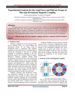
  • 1. International Journal of Engineering and Techniques - Volume 2 Issue 1, Jan - Feb 2016 ISSN: 2395-1303 http://www.ijetjournal.org Page 21 Experimental Analysis for the Axial Force and Pull-out Torque of Disc type Permanent Magnetic Coupling Jitendra Sharad Narkhede1 , Dr.Kishor B. Waghulde2 1(ME Student,, Department of Mechanical Engineering,J. T. Mahajan college of engineering, Faizpur (NMU), Maharashtra, India) 2 ( Professor, Department of Mechanical Engineering, J. T. Mahajan college of engineering, Faizpur (NMU), Maharashtra, India) I. INTRODUCTION Magnetic couplings are used to transmit torque from a primary driver to a load without any mechanical contact. As the torque could be transmitted across a separation wall, magnetic couplings are well suited for use in isolated systems. Among the advantages of this type of coupling compared to mechanical couplings is the self- protection against the overload (pull-out torque). Moreover, magnetic couplings tolerate shaft misalignment. As shown in Fig. 1, the studied axial magnetic coupling consists of two discs equipped with sector-shaped permanent magnets (rare-earth magnets) and separated by a small air-gap. The magnets are axially magnetized and are arranged to obtain alternately north and south poles. Soft-iron yokes are used to close the flux. Through magnetic interaction, the torque applied to one disc is transferred through an air-gap to the other disc. Ordinary couplings need mechanical contact and lubrication, resulting in dust, noise, and maintenance of the systems. In order to solve these problems, magnetic couplings are of considerable interest in many industrial applications because they can transmit torque from a primary driver to a follower, without mechanical contact. In particular, as the torque could be transmitted across a separation wall, axial permanent magnetic couplings (APMCs) are well suited for isolated systems such as vacuums or high-pressure vessel. An event such as a frequently operating overload or damage in the mechanical couplings may occur, causing parts to break and scatter. In such a situation, the APMCs would not create any broken parts, and the magnetic slip offers the torque limit function via prediction of the accurate torque characteristics. A. Geometry of the Axial Magnetic Coupling Fig. 1 Geometry of the studied axial magnetic coupling This two piece rare-earth permanent magnet coupling is for contact-free torque transmission through any non-ferrous wall, with the benefit of slipping when Abstract: This paper presents the pull-out torque and axial force analysis of a disc type permanent magnetic coupling under steady state. This magnetic coupling employ rear-earth permanent magnets. The pull-out torque and axial force of magnetic calculated by changing the air-gap between two disc as a function of geometrical parameters. And its shows that if length of air-gap is increases pull-out torque and axial force is decreases. The experimental analysis results are verified by carrying out measurement on a prototype. Keywords — Pull-out torque, Disc type magnetic coupling, axial force, Analytical Model, Permanent magnets. RESEARCH ARTICLE OPEN ACCESS
  • 2. International Journal of Engineering and Techniques ISSN: 2395-1303 the maximum torque is exceeded, mechanical components in the drive line from damage. Magnetic couplings are of great interest in many industrial applications. They can transmit a torque from a primary driver to a follower without mechanical contact. As the torque could be transmitted across a separation wall, axial field magnetic couplings are well suited for use in isolated systems such as vacuum or high pressure vessels. Moreover, they present a maximum transmissible torque (pull-out torque) giving an intrinsic overload protection. Axial magnetic couplings consist of two opposing discs equipped with rare earth permanent magnets. The magnets are magnetized in the axial direction. They are arranged to obtain alternately north and south poles. The flux is closed by soft-iron yokes. The torque applied to one disc is transferred through an air to the other disc. The angular shift between the two discs depends on the transmitted torque value. The main drawback of axial-type magnetic couplings is the significant value of the axial attractive force between the two discs. Permanent magnet couplings (SPMCs) are used to transmit torques between two rotating parts without mechanical contact. They are widely used in industrial applications e.g. ammonia pumps and centrifugal pumps for ph and chemical industries. In particular, the coaxial type device is suitable for high torque demands. Knowledge regarding the SPMC pull- very important because this torque acts as an overload protection. II. FABRICATION OF MAGNETIC COUPLING A. How disc coupling works Disc couplings consist of opposing discs with powerfulrare earth magnets. The torque applied to one disc istransferred through an air gap to the other disc.Because of the simple flat design, you can have angularmisalignment of up to 3 or a parallel misalignment of upto 6mm and still transmit nearly full rotational torque.Easily isolate drive side components from clean or containedprocesses.This is our simplest and most versatile coupling. B. Parameters of axial magnetic coupling International Journal of Engineering and Techniques - Volume 2 Issue 1, Jan - http://www.ijetjournal.org the maximum torque is exceeded, protecting mechanical components in the drive line from couplings are of great interest in many industrial applications. They can transmit a torque from a primary driver to a follower without mechanical contact. As the torque could be smitted across a separation wall, axial field magnetic couplings are well suited for use in isolated systems such as vacuum or high pressure vessels. Moreover, they present a maximum out torque) giving an ction. Axial magnetic couplings consist of two opposing discs equipped with rare earth permanent magnets. The magnets are magnetized in the axial direction. They are arranged to obtain alternately north and south poles. es. The torque applied to one disc is transferred through an air-gap to the other disc. The angular shift between the two discs depends on the transmitted torque value. The type magnetic couplings is l attractive force Permanent magnet couplings (SPMCs) are used to transmit torques between two rotating parts without mechanical contact. They are widely used in industrial applications e.g. ammonia pumps and centrifugal pumps for pharmaceutical and chemical industries. In particular, the coaxial type device is suitable for high torque demands. -out torque is very important because this torque acts as an MAGNETIC Disc couplings consist of opposing discs with powerfulrare earth magnets. The torque applied to one disc istransferred through an air gap to the other disc.Because of the simple flat design, you can have angularmisalignment of up to 3 or a parallel misalignment of upto 6mm and still transmit nearly full rotational torque.Easily isolate drive side components from clean or containedprocesses.This is our simplest and most versatile coupling. TABLE 1 PARAMETERS OF AXIAL MAGNETIC Symbol Specification R1 Inner radius of the magnet R2 Outer radius of the magnet Re Mean radius of the magnet ϕ Axial angle of magnet arranged g Air-gap length h Magnet thickness p Number of pole Br Remanence of permanent magnet -- Surface gauss value 1) Magnet material - Neodymium magnet Take iron discs of diameter 75 mm, mark angle on same disc as it divides to four angular positions i.e900 . The neodymium magnets of cylindrical shape fixed by (lock-tite) industrial glue. Same arrangement is done to second disc. One disc of magnetic coupling is assembled to shaft of motor and second disc of coupling is arrange on adjustable screw by bearing. Due to that changes of air possible. III. EXPERIMENTAL SET-UP AND MEASUREMENT Fig. 2 Block diagram of experimental set A. Experimental set-up Fig.3 Actual experimental set - Feb 2016 Page 22 MAGNETIC COUPLING Value Inner radius of the magnet 25 mm Outer radius of the magnet 75 mm Mean radius of the magnet 50 mm Axial angle of magnet arranged 900 Variable 10 mm 4 Remanence of permanent magnet 12.8 T 4.6 kilogauss Neodymium magnet (NdFeB) Take iron discs of diameter 75 mm, mark angle on same disc as it divides to four angular positions . The neodymium magnets of cylindrical tite) industrial glue. Same angement is done to second disc. One disc of magnetic coupling is assembled to shaft of motor and second disc of coupling is arrange on adjustable screw by bearing. Due to that changes of air-gap is UP AND Fig. 2 Block diagram of experimental set-up Fig.3 Actual experimental set-up
  • 3. International Journal of Engineering and Techniques ISSN: 2395-1303 Fig.3 shows the axial magnetic coupling placed on the test bench. The axial coupling is inserted between fixed rotor and electrical machine. In fig.3 the air-gap value is e = 20 mm. The air length has been set by moving fixed rotor. Figs. 2 and 3shows a photograph and a block representation of the test bench arrangement for the static torque measurement respectively. The static torque was measured thanks to weights (10g, 20g, 50g, 100g, 500g, 1kg) suspended to a rod (l = 0.137 m) locked to one rotor, the other being fixed. And following readings are taken. B. Torque calculated as the air gap of magnetic coupling is changes TABLE.2 EXPERIMENTAL RESULTS Sr. No. Air Gap (mm) Force applied F (N) Distance to load applied r (m) 1 15 16.68 0.137 2 20 7.85 0.137 3 25 5.89 0.137 4 30 3.92 0.137 5 35 2.95 0.137 6 40 1.48 0.137 IV. GRAPH A. Comparison between air-gap and axial force Graph 1 – Air-gap vs Axial force applied B. Comparison between Air-gap and pull-out torque 16.68 7.85 5.89 3.92 2.95 15 20 25 30 35 AxialForce(N) Air-gap length (mm) International Journal of Engineering and Techniques - Volume 2 Issue 1, Jan - http://www.ijetjournal.org Fig.3 shows the axial magnetic coupling placed on the test bench. The axial coupling is inserted between fixed rotor and electrical machine. = 20 mm. The air-gap length has been set by moving fixed rotor. Figs. 2 a photograph and a block-scheme representation of the test bench arrangement for the static torque measurement respectively. The static torque was measured thanks to weights (10g, 20g, 50g, 100g, 500g, 1kg) suspended to a rod (l = 0.137 tor, the other being fixed. And Torque calculated as the air gap of magnetic coupling Torque F*r(Nm) 2.29 1.08 0.81 0.54 0.40 0.21 gap and axial force gap vs Axial force applied out torque Graph 2 – Air-gap vs Pull-out torque V. CONCLUSION From the experimental analysis it observed that there is a torque variation obtained as the changes of air-gap. As the air-gap is changed from minimum to maximum value there is a decr torque as well as force applied. of the magnetic coupling decreases quickly as the distance between the magnets increases. The maximum torque is almost divided by two when the air-gap is increased from 2mm to 7mm. In the same way, the maximal axial force is reduced when the air-gap length increases. The optimal number of pole pairs is p = 4 if we consider an air = 15mm. We can observe that the maximum axial force decreases when the number of pole pairs increases.Also it observed that if the magnetic poles are increased the results obtained are different. The results and observation shows that the drive is positively maintained as any change of air gap length is changed. ACKNOWLEDGMENT I offer my gratitude and it i acknowledge indebtedness to my estimated guide Dr. K.B.Waghuldeand Co-ordinatorDr. M.M.Patil. It is stern guidance and grandeur of him which has brought this work in a proper channel. This guidance not only helps me to collect the knowledge but also to gain the confidence which would help me in future. My association with him as a student has been extreme pleasing.I pay my sincere thanks to Prof. D. A. Warke, HOD of 2.29 1.08 0.81 0.54 15 20 25 30 Pull-outtorque(Nmm) Air-gap length (mm) 1.48 40 - Feb 2016 Page 23 out torque From the experimental analysis it observed that there is a torque variation obtained as the gap is changed from minimum to maximum value there is a decrease in The pull-out torque of the magnetic coupling decreases quickly as the distance between the magnets increases. The maximum torque is almost divided by two when the gap is increased from 2mm to 7mm. In the same y, the maximal axial force is reduced when the The optimal number of = 4 if we consider an air-gap length e = 15mm. We can observe that the maximum axial force decreases when the number of pole pairs it observed that if the magnetic poles are increased the results obtained are different. The results and observation shows that the drive is positively maintained as any change of air gap I offer my gratitude and it is my privilege to acknowledge indebtedness to my estimated guide ordinatorDr. M.M.Patil. It is stern guidance and grandeur of him which has brought this work in a proper channel. This guidance not only helps me to collect the ge but also to gain the confidence which would help me in future. My association with him as a student has been extreme pleasing.I pay my sincere thanks to Prof. D. A. Warke, HOD of 0.4 0.2 35 40 gap length (mm)
  • 4. International Journal of Engineering and Techniques - Volume 2 Issue 1, Jan - Feb 2016 ISSN: 2395-1303 http://www.ijetjournal.org Page 24 Mechanical Engineering Department. I would also like to thank Principal Dr. Bimlesh Kumarsir for his encouragement and valuable suggestions.Finally heartfelt appreciation to the all those who directly and indirectly helped me in completion of this experiment. REFERENCES 1. Hyeon-Jae Shin, Jang-Young Choi Seok- Myeong Jang , and Kwang-Youn Lim,”Design and Analysis of Axial Permanent Magnet Couplings Based on 3-D FEM”, Department of Electrical Engineering, Chungnam National University, Daejeon, IEEE Transactions on Energy Conversion 7, July 2013. 2. Thierry Lubin, Smail Mezani, and Abderrezak Rezzoug,”Simple Analytical Expressions for the Force and Torque of Axial Magnetic Couplings”, IEEE Transactions on Energy Conversion 2012. 3. Thierry Lubin, Smail Mezani, and Abderrezak Rezzoug,”Experimental and Theoretical Analysis of Axial Magnetic Coupling under Steady-State and Transient Operation”,IEEE Transactions on Industrial Electronics 2013. 4. Jang-Young Choi , Hyeon-Jae Shin , Seok- Myeong Jang ,and Sung-Ho Lee,”Torque Analysis and Measurements of Cylindrical Air- Gap Synchronous Permanent Magnet Couplings Based on Analytical Magnetic Field Calculations”,IEEE Transactions On Magnetics, Vol. 49, No. 7, July 2013. 5. Thierry Lubin, and Abderrezak Rezzoug,”Steady-State and Transient Performance of Axial-Field Eddy-Current Coupling”,IEEE Transactions on Industrial Electronics 2014.