SlideShare a Scribd company logo
1 of 8
Download to read offline
Thermodynamic Design of a Fire-Tube
Steam Boiler
Prepared for:
Professor Kamran Shavezipur
Prepared by:
(Team 16)
John Walter
Austen Kennedy
Muhammad Shuhaimi
December 11th
, 2014
2
Table of Contents
Introduction ..................................................................................................................................................3
Design Analysis and Calculations……………………………………………………………………………………………………………..4
Design Outcome……………………………………………………………………………………………………………………………………...6
References …………………………………………………………………………………………………………………………………………… .8
3
Introduction:
The body of the boiler is usually the pressure vessel and contains the fluid. The fluid is normally
the water which will circulate for heating purposes and sometimes is converted to steam for
process use. The horizontal fire tube boiler has three passes. The first pass consists of furnace
while both of the second and third passes consist of tubes. While the fire tube boiler operates,
only the second and third passes are considered for the heat transfer process.
The advantages of the fire tube boiler are the cost is inexpensive, easy to clean, compact in size,
easy to replace tubes, and well suited for space heating and industrial process applications. The
disadvantages of the fire tube boiler are not suitable for high pressure applications and it has
limitation for high capacity steam generation.
This is the list of the main components in the fire tube boiler:
o Boiler shell is the outer component in a cylindrical shape that covers the pressure vessel.
o Burner is located in the vertical walls of the furnace and it brings fuel and air into the
furnace at the desired velocities, turbulence and concentration.
o Furnace is the enclosed space where the combustion takes place.
o Drain is the valve connection that removes all the water from the pressure parts.
o Feed Pump supplies water to the boiler
o Safety valve is a spring loaded valve that automatically opens when pressure attains the
valve setting. It is used to prevent excessive pressure from building up in the boiler.
o Steam separator removes the entrained water from steam
o Firebox absorbs radiant heat from the fire.
o Accumulator stores the heat of steam to be used during late period and at lower pressure.
o Insulation is made from a material of low thermal conductivity and is sued to reduce
heat losses.
o Safety shut-off valve is electrically operated to automatically shut off fuel when de-
energized.
o Circulator is used to pass steam or water between upper boiler drum which is usually
located where the heat absorption is low.
o Strainer is a filter that is used to retain solid particles allowing a liquid to get pass.
o Breeching transports the product for the production between parts of the generating unit.
4
Design Analysis and Calculations:
Temperature Distribution
Tw=180 degC (Given value for water)
Heat Transfer within the Steam Boiler
To find both Q values, the equation for Qin is used. After the Qin is solved, different amounts that each
Q2 and Q3 contribute to the Qin are tested in the excel file. The Q2 and Q3 values that are used are the
ones that allow the areas A2 and A3 to be relatively close to each other.
̇
hg at 10 bar is used because the given pressure was 10 bar for within the tube. hf at 21 degC is used
because this is around what the temperature of water would be outside of the tube before it enters.
̇ ( )
After testing different percentages in the excel document, the best ones to use were 72% for Q2 and
28% for Q3:
5
Area for A2 and A3 are solved for using Q2 and Q3 values and Q/A values:
Volume Ratio
Volume values were determined using the design that was completed on the solidworks program as well
as the values that are displayed in the design outcome.
The volume of vapor was determined by seeing that roughly 10 percent of the total front area
was empty at the top. This is where the vapor would be present above the water.
Tube area and number of tubes
The surface area of the tubes were calculated using the assumed tube diameter.
The number of tubes for each pass were found by dividing A2 and A3 by the tube A_tube.
6
Design Outcome:
There were many assumed and given values used for the design of the steam boiler system.
Given Values:
- The tube external diameter is 50mm, and its thickness is 3 mm.
-The thickness of furnace plate is 16mm
-The thickness of main shell is 12 mm.
-Tube diameter is 50mm
Values determined by team:
- Boiler length: 5m
- Boiler Diameter: 2m
- Furnace Diameter: 0.8m
7
Excel Data (Also sent in a separate Excel File)
Assumed/Given
mass flow rate (kg/s) 1.39
pressure (Pa) 1000000
boiler length (m) 5
boiler diameter (m) 2
tubes diameter (m) 0.8
h-w 700
h-air 75
k-tube 51
t-tube (m) 0.003
T1 (celsius) 1100
T3 (celsius) 230
T-w (celcius) 180
Calculated/Determined
T2 665 h2 2778.1
T2-air 882.5 h1 88.14
T3-air 447.5
Q-in 3739.044
Q2/A2 47.39983
Q3/A3 18.04905
Q2 2692.112
Q3 1046.932
A2 56.79581
A3 58.00486
Area of tube 0.789
Number of tubes: Pass 2 72
Number of tubes: Pass 3 74
Total Number of Tubes 146
8
References
Godil. Junaid. Boiler. Web. 10 Dec 2014. <http://www.nedians.8m.com/boiler.htm>
Firetube or Watertube? What is the difference? P.C.Mc.Kenzie Company. Web. 10 Dec 2014.
http://www.mckenziecorp.com/boiler_tip_8.htm
http://www.energy.kth.se/compedu/webcompedu/ManualCopy/Steam_Boiler_Technology/Heat_
exchangers/thermal_design_of_heat_exchangers.pdf

More Related Content

What's hot

Heat Exchanger recuperators
Heat Exchanger  recuperators  Heat Exchanger  recuperators
Heat Exchanger recuperators
Ali Abdullah
 
DESIGN OF AIR PRE HEATER AND ECONOMIZER
DESIGN OF AIR PRE HEATER AND ECONOMIZERDESIGN OF AIR PRE HEATER AND ECONOMIZER
DESIGN OF AIR PRE HEATER AND ECONOMIZER
Gopi Chand
 
DESIGN OF AIR PRE HEATER AND ECONOMIZER
DESIGN OF AIR PRE HEATER AND ECONOMIZERDESIGN OF AIR PRE HEATER AND ECONOMIZER
DESIGN OF AIR PRE HEATER AND ECONOMIZER
Gopi Chand
 
Calculation of Turbine Efficiency
Calculation of Turbine EfficiencyCalculation of Turbine Efficiency
Calculation of Turbine Efficiency
Jahanzeb Khan
 

What's hot (20)

Performance evaluation and optimization of air preheater in thermal power plant
Performance evaluation and optimization of air preheater in thermal power plantPerformance evaluation and optimization of air preheater in thermal power plant
Performance evaluation and optimization of air preheater in thermal power plant
 
Design of superheater for 210 MW thermal powerplant final
Design of superheater for 210 MW thermal powerplant finalDesign of superheater for 210 MW thermal powerplant final
Design of superheater for 210 MW thermal powerplant final
 
Heat Exchanger recuperators
Heat Exchanger  recuperators  Heat Exchanger  recuperators
Heat Exchanger recuperators
 
DESIGN OF AIR PRE HEATER AND ECONOMIZER
DESIGN OF AIR PRE HEATER AND ECONOMIZERDESIGN OF AIR PRE HEATER AND ECONOMIZER
DESIGN OF AIR PRE HEATER AND ECONOMIZER
 
Pinch analysis technique to optimize heat exchanger
Pinch analysis technique to optimize heat exchangerPinch analysis technique to optimize heat exchanger
Pinch analysis technique to optimize heat exchanger
 
Study and Analysis of Tube Failure in Water Tube boiler
Study and Analysis of Tube Failure in Water Tube boilerStudy and Analysis of Tube Failure in Water Tube boiler
Study and Analysis of Tube Failure in Water Tube boiler
 
DESIGN OF AIR PRE HEATER AND ECONOMIZER
DESIGN OF AIR PRE HEATER AND ECONOMIZERDESIGN OF AIR PRE HEATER AND ECONOMIZER
DESIGN OF AIR PRE HEATER AND ECONOMIZER
 
Boiler Efficiency Calculations
Boiler Efficiency CalculationsBoiler Efficiency Calculations
Boiler Efficiency Calculations
 
Calculation of Turbine Efficiency
Calculation of Turbine EfficiencyCalculation of Turbine Efficiency
Calculation of Turbine Efficiency
 
Plate Type Heat Exchanger Design
Plate Type Heat Exchanger DesignPlate Type Heat Exchanger Design
Plate Type Heat Exchanger Design
 
Process calculation condensation
Process calculation  condensationProcess calculation  condensation
Process calculation condensation
 
Turbine cycle heat rate calculation
Turbine  cycle heat rate calculationTurbine  cycle heat rate calculation
Turbine cycle heat rate calculation
 
Air Preheat System Upgrade on Coker Heaters
Air Preheat System Upgrade on Coker HeatersAir Preheat System Upgrade on Coker Heaters
Air Preheat System Upgrade on Coker Heaters
 
Training material for air preheater
Training material for air preheaterTraining material for air preheater
Training material for air preheater
 
Marcet boiler
Marcet boiler Marcet boiler
Marcet boiler
 
Steam Turbine Performance in TPS
Steam Turbine Performance in TPSSteam Turbine Performance in TPS
Steam Turbine Performance in TPS
 
Feed water and condensate heaters
Feed water and condensate heatersFeed water and condensate heaters
Feed water and condensate heaters
 
Condenser design
Condenser designCondenser design
Condenser design
 
Steam generator part 2
Steam generator part 2Steam generator part 2
Steam generator part 2
 
Design of condenser
Design of condenserDesign of condenser
Design of condenser
 

Similar to Thermodynamic Design of a Fire-Tube Steam Boiler

Thermodynamic Design of a Fire-Tube Steam Boiler
Thermodynamic Design of a Fire-Tube Steam BoilerThermodynamic Design of a Fire-Tube Steam Boiler
Thermodynamic Design of a Fire-Tube Steam Boiler
John Walter
 
Heat exchanger design project
Heat exchanger design project Heat exchanger design project
Heat exchanger design project
Chinedu Isiadinso
 
Fireplace Heat Exchanger Design
Fireplace Heat Exchanger DesignFireplace Heat Exchanger Design
Fireplace Heat Exchanger Design
Christopher Cho
 
H&MProject_TylerLenzen_Spring2014
H&MProject_TylerLenzen_Spring2014H&MProject_TylerLenzen_Spring2014
H&MProject_TylerLenzen_Spring2014
Tyler Lenzen
 
2011 04-th chongsw
2011 04-th chongsw2011 04-th chongsw
2011 04-th chongsw
Thanh Nguyen
 
A Thesis on Design Optimization of Heat Sink in Power Electronics
A Thesis on Design Optimization of Heat Sink in Power ElectronicsA Thesis on Design Optimization of Heat Sink in Power Electronics
A Thesis on Design Optimization of Heat Sink in Power Electronics
IJERA Editor
 
Experimentation on heat pipe and cfd analysis for performance enhancement
Experimentation on heat pipe and cfd analysis for performance enhancementExperimentation on heat pipe and cfd analysis for performance enhancement
Experimentation on heat pipe and cfd analysis for performance enhancement
eSAT Journals
 
Experimentation on heat pipe and cfd analysis for performance enhancement
Experimentation on heat pipe and cfd analysis for performance enhancementExperimentation on heat pipe and cfd analysis for performance enhancement
Experimentation on heat pipe and cfd analysis for performance enhancement
eSAT Journals
 
Department of Mechanical Engineering ME 440 Project D
 Department of Mechanical Engineering ME 440 Project D Department of Mechanical Engineering ME 440 Project D
Department of Mechanical Engineering ME 440 Project D
troutmanboris
 
Department of Mechanical Engineering ME 440 Project D.docx
 Department of Mechanical Engineering ME 440 Project D.docx Department of Mechanical Engineering ME 440 Project D.docx
Department of Mechanical Engineering ME 440 Project D.docx
ShiraPrater50
 
Marnus Koorts - Masters Project
Marnus Koorts - Masters ProjectMarnus Koorts - Masters Project
Marnus Koorts - Masters Project
Marnus Koorts
 

Similar to Thermodynamic Design of a Fire-Tube Steam Boiler (20)

Thermodynamic Design of a Fire-Tube Steam Boiler
Thermodynamic Design of a Fire-Tube Steam BoilerThermodynamic Design of a Fire-Tube Steam Boiler
Thermodynamic Design of a Fire-Tube Steam Boiler
 
REPORT-MSD
REPORT-MSDREPORT-MSD
REPORT-MSD
 
Heat exchanger design project
Heat exchanger design project Heat exchanger design project
Heat exchanger design project
 
Fireplace Heat Exchanger Design
Fireplace Heat Exchanger DesignFireplace Heat Exchanger Design
Fireplace Heat Exchanger Design
 
Ijri te-03-012 design and optimization of water cool condenser for central ai...
Ijri te-03-012 design and optimization of water cool condenser for central ai...Ijri te-03-012 design and optimization of water cool condenser for central ai...
Ijri te-03-012 design and optimization of water cool condenser for central ai...
 
H&MProject_TylerLenzen_Spring2014
H&MProject_TylerLenzen_Spring2014H&MProject_TylerLenzen_Spring2014
H&MProject_TylerLenzen_Spring2014
 
2011 04-th chongsw
2011 04-th chongsw2011 04-th chongsw
2011 04-th chongsw
 
Boiler
BoilerBoiler
Boiler
 
FEEMSSD presentation on shell and tube heat exchanger75 .pptx
FEEMSSD presentation on shell and tube heat exchanger75 .pptxFEEMSSD presentation on shell and tube heat exchanger75 .pptx
FEEMSSD presentation on shell and tube heat exchanger75 .pptx
 
Radial heat conduction
Radial heat conductionRadial heat conduction
Radial heat conduction
 
A Thesis on Design Optimization of Heat Sink in Power Electronics
A Thesis on Design Optimization of Heat Sink in Power ElectronicsA Thesis on Design Optimization of Heat Sink in Power Electronics
A Thesis on Design Optimization of Heat Sink in Power Electronics
 
Experimentation on heat pipe and cfd analysis for performance enhancement
Experimentation on heat pipe and cfd analysis for performance enhancementExperimentation on heat pipe and cfd analysis for performance enhancement
Experimentation on heat pipe and cfd analysis for performance enhancement
 
Experimentation on heat pipe and cfd analysis for performance enhancement
Experimentation on heat pipe and cfd analysis for performance enhancementExperimentation on heat pipe and cfd analysis for performance enhancement
Experimentation on heat pipe and cfd analysis for performance enhancement
 
Be project - PRDS (Pressure Reducing And Desuperheater Station)
Be project - PRDS (Pressure Reducing And Desuperheater Station)Be project - PRDS (Pressure Reducing And Desuperheater Station)
Be project - PRDS (Pressure Reducing And Desuperheater Station)
 
Department of Mechanical Engineering ME 440 Project D
 Department of Mechanical Engineering ME 440 Project D Department of Mechanical Engineering ME 440 Project D
Department of Mechanical Engineering ME 440 Project D
 
Department of Mechanical Engineering ME 440 Project D.docx
 Department of Mechanical Engineering ME 440 Project D.docx Department of Mechanical Engineering ME 440 Project D.docx
Department of Mechanical Engineering ME 440 Project D.docx
 
01 kern's method.
01 kern's method.01 kern's method.
01 kern's method.
 
Gagan nir s103217540 capston_project_presentation
Gagan nir s103217540 capston_project_presentationGagan nir s103217540 capston_project_presentation
Gagan nir s103217540 capston_project_presentation
 
Marnus Koorts - Masters Project
Marnus Koorts - Masters ProjectMarnus Koorts - Masters Project
Marnus Koorts - Masters Project
 
C1303071722
C1303071722C1303071722
C1303071722
 

Thermodynamic Design of a Fire-Tube Steam Boiler

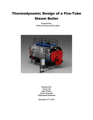
  • 1. Thermodynamic Design of a Fire-Tube Steam Boiler Prepared for: Professor Kamran Shavezipur Prepared by: (Team 16) John Walter Austen Kennedy Muhammad Shuhaimi December 11th , 2014
  • 2. 2 Table of Contents Introduction ..................................................................................................................................................3 Design Analysis and Calculations……………………………………………………………………………………………………………..4 Design Outcome……………………………………………………………………………………………………………………………………...6 References …………………………………………………………………………………………………………………………………………… .8
  • 3. 3 Introduction: The body of the boiler is usually the pressure vessel and contains the fluid. The fluid is normally the water which will circulate for heating purposes and sometimes is converted to steam for process use. The horizontal fire tube boiler has three passes. The first pass consists of furnace while both of the second and third passes consist of tubes. While the fire tube boiler operates, only the second and third passes are considered for the heat transfer process. The advantages of the fire tube boiler are the cost is inexpensive, easy to clean, compact in size, easy to replace tubes, and well suited for space heating and industrial process applications. The disadvantages of the fire tube boiler are not suitable for high pressure applications and it has limitation for high capacity steam generation. This is the list of the main components in the fire tube boiler: o Boiler shell is the outer component in a cylindrical shape that covers the pressure vessel. o Burner is located in the vertical walls of the furnace and it brings fuel and air into the furnace at the desired velocities, turbulence and concentration. o Furnace is the enclosed space where the combustion takes place. o Drain is the valve connection that removes all the water from the pressure parts. o Feed Pump supplies water to the boiler o Safety valve is a spring loaded valve that automatically opens when pressure attains the valve setting. It is used to prevent excessive pressure from building up in the boiler. o Steam separator removes the entrained water from steam o Firebox absorbs radiant heat from the fire. o Accumulator stores the heat of steam to be used during late period and at lower pressure. o Insulation is made from a material of low thermal conductivity and is sued to reduce heat losses. o Safety shut-off valve is electrically operated to automatically shut off fuel when de- energized. o Circulator is used to pass steam or water between upper boiler drum which is usually located where the heat absorption is low. o Strainer is a filter that is used to retain solid particles allowing a liquid to get pass. o Breeching transports the product for the production between parts of the generating unit.
  • 4. 4 Design Analysis and Calculations: Temperature Distribution Tw=180 degC (Given value for water) Heat Transfer within the Steam Boiler To find both Q values, the equation for Qin is used. After the Qin is solved, different amounts that each Q2 and Q3 contribute to the Qin are tested in the excel file. The Q2 and Q3 values that are used are the ones that allow the areas A2 and A3 to be relatively close to each other. ̇ hg at 10 bar is used because the given pressure was 10 bar for within the tube. hf at 21 degC is used because this is around what the temperature of water would be outside of the tube before it enters. ̇ ( ) After testing different percentages in the excel document, the best ones to use were 72% for Q2 and 28% for Q3:
  • 5. 5 Area for A2 and A3 are solved for using Q2 and Q3 values and Q/A values: Volume Ratio Volume values were determined using the design that was completed on the solidworks program as well as the values that are displayed in the design outcome. The volume of vapor was determined by seeing that roughly 10 percent of the total front area was empty at the top. This is where the vapor would be present above the water. Tube area and number of tubes The surface area of the tubes were calculated using the assumed tube diameter. The number of tubes for each pass were found by dividing A2 and A3 by the tube A_tube.
  • 6. 6 Design Outcome: There were many assumed and given values used for the design of the steam boiler system. Given Values: - The tube external diameter is 50mm, and its thickness is 3 mm. -The thickness of furnace plate is 16mm -The thickness of main shell is 12 mm. -Tube diameter is 50mm Values determined by team: - Boiler length: 5m - Boiler Diameter: 2m - Furnace Diameter: 0.8m
  • 7. 7 Excel Data (Also sent in a separate Excel File) Assumed/Given mass flow rate (kg/s) 1.39 pressure (Pa) 1000000 boiler length (m) 5 boiler diameter (m) 2 tubes diameter (m) 0.8 h-w 700 h-air 75 k-tube 51 t-tube (m) 0.003 T1 (celsius) 1100 T3 (celsius) 230 T-w (celcius) 180 Calculated/Determined T2 665 h2 2778.1 T2-air 882.5 h1 88.14 T3-air 447.5 Q-in 3739.044 Q2/A2 47.39983 Q3/A3 18.04905 Q2 2692.112 Q3 1046.932 A2 56.79581 A3 58.00486 Area of tube 0.789 Number of tubes: Pass 2 72 Number of tubes: Pass 3 74 Total Number of Tubes 146
  • 8. 8 References Godil. Junaid. Boiler. Web. 10 Dec 2014. <http://www.nedians.8m.com/boiler.htm> Firetube or Watertube? What is the difference? P.C.Mc.Kenzie Company. Web. 10 Dec 2014. http://www.mckenziecorp.com/boiler_tip_8.htm http://www.energy.kth.se/compedu/webcompedu/ManualCopy/Steam_Boiler_Technology/Heat_ exchangers/thermal_design_of_heat_exchangers.pdf