
![Check Anchor head bearing
Area of the anchor head (Ah ) (including the area of the tensile stress
component) is at least 2.5 times the area of the tensile stress
component.
2
π dh 4 2
Ah 5.067 10 m
4
Ah
4 Must be more than 2.5
As
dh ds
c1 0.25 in
2
check2 if Th c1 "ok" "no good" "ok"
Determine the embedment of the stud
The design pullout strength of the concrete, Pd , must exceed the minimum specified
tensile strength (Asfut ) of the tensile stress component.
As fut 11.781 kip
0.65 4 psi fc 164.438 psi
Acp = [(Ld + dh /2)^2– (dh /2)^2]
dh
2 2
dh
Pc π Ld 0.65 4 psi fc 15.498 kip
2 2
check3 if Pc As fut "ok" "no good" "ok"
By Khaled Eid, PE email khaled_eid@yahoo.com](data:image/gif;base64,R0lGODlhAQABAIAAAAAAAP///yH5BAEAAAAALAAAAAABAAEAAAIBRAA7)
Recomendados
Recomendados
Más contenido relacionado
La actualidad más candente
La actualidad más candente (20)
Más de Khaled Eid
Más de Khaled Eid (14)
Último
Último (20)
Mathcad anchors (2)
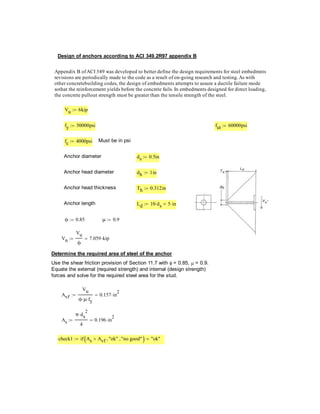
- 1. Design of anchors according to ACI 349.2R97 appendix B Appendix B of ACI 349 was developed to better define the design requirements for steel embedmnts revisions are periodically made to the code as a result of on-going research and testing. As with other concretebuilding codes, the design of embedments attempts to assure a ductile failure mode sothat the reinforcement yields before the concrete fails. In embedments designed for direct loading, the concrete pullout strength must be greater than the tensile strength of the steel. Vu 6kip fy 50000psi fut 60000psi fc 4000psi Must be in psi Anchor diameter d s 0.5in Anchor head diameter d h 1in Anchor head thickness Th 0.312in Anchor length Ld 10 d s 5 in ϕ 0.85 μ 0.9 Vu Vn 7.059 kip ϕ Determine the required area of steel of the anchor Use the shear friction provision of Section 11.7 with = 0.85, = 0.9. Equate the external (required strength) and internal (design strength) forces and solve for the required steel area for the stud. Vu 2 Avf 0.157 in ϕ μ fy 2 π d s 2 As 0.196 in 4 check1 if As Avf "ok" "no good" "ok"
- 2. Check Anchor head bearing Area of the anchor head (Ah ) (including the area of the tensile stress component) is at least 2.5 times the area of the tensile stress component. 2 π dh 4 2 Ah 5.067 10 m 4 Ah 4 Must be more than 2.5 As dh ds c1 0.25 in 2 check2 if Th c1 "ok" "no good" "ok" Determine the embedment of the stud The design pullout strength of the concrete, Pd , must exceed the minimum specified tensile strength (Asfut ) of the tensile stress component. As fut 11.781 kip 0.65 4 psi fc 164.438 psi Acp = [(Ld + dh /2)^2– (dh /2)^2] dh 2 2 dh Pc π Ld 0.65 4 psi fc 15.498 kip 2 2 check3 if Pc As fut "ok" "no good" "ok" By Khaled Eid, PE email khaled_eid@yahoo.com