1. 1
CS8603 – DISTRIBUTED SYSTEMS
UNIT I – INTRODUCTION
Introduction: Definition –Relation to computer system components –Motivation –Relation to parallel systems
– Message-passing systems versus shared memory systems –Primitives for distributed communication –
Synchronous versus asynchronous executions –Design issues and challenges. A model of distributed computations:
A distributed program –A model of distributed executions –Models of communication networks –Global state –
Cuts –Past and future cones of an event –Models of process communications. Logical Time: A framework for a
system of logical clocks –Scalar time –Vector time – Physical clock synchronization: NTP.
Distributed System
Definition
A distributed system is a collection of independent entities that
cooperate to solve a problem that cannot be individually solved.
A distributed system is the one in which hardware or software
components located at networked computers communicate and
coordinate their actions only by passing messages each having its own
memory and operating system.
Characteristics of distributed system:
• It is a collection of autonomous processors communicating over a
communication network have the following features:
• No common physical clock.
• No shared memory.
o hence it requires message-passing for communication and
implies the absence of common physical clock.
o distributed system provides the abstraction of common address
space via distributed shared memory abstraction.
• Geographical separation
• The geographically wider apart processors are the representative
of a distributed system i.e., it may be in wide-area network
(WAN) or the network/cluster of workstations (NOW/COW)
configuration connecting processors on a LAN
• NOW configuration is the low-cost high-speed off-the-shelf
processors. Example: Google search engine.
• Autonomy and heterogeneity
• The processors are “loosely coupled” having different speeds and
each runs different operating system but cooperate with one
another by offering services for solving a problem jointly.
Relation to computer system components
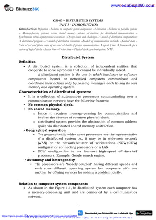
As shown in the Figure 1.1, In distributed system each computer has
a memory-processing unit and are connected by a communication
network.
www.rejinpaul.com
Download Useful Materials @ www.rejinpaul.com
https://play.google.com/store/apps/details?id=com.sss.edubuzz360
www.edubuzz360.com
2. 2
Figure 1.2 shows the relationships of software components that run
on computers use the local operating system and network protocol
stack for functioning.
A distributed software is also termed as middleware.
A distributed execution is the execution of processes across the
distributed system to collaboratively achieve a common goal which is
also termed a computation or a run.
A distributed system follows a layered architecture that reduces the
complexity of the system design.
Middleware hides the heterogeneity transparently at the platform level.
(Fig.1.1 A distributed system connects processors by a communication network)
(Fig.1.2 Interaction of the software components at each processor)
It is assumed that the middleware layer does not contain the
application layer functions like http, mail, ftp, and telnet.
User program code includes the code to invoke libraries of the
middleware layer to support the reliable and ordered multicasting.
There are several standards such as
Object Management Group’s (OMG) common object request broker
architecture (CORBA) ,
RPC software
o sends a message across the network to invoke the remote
procedure.
www.rejinpaul.com
Download Useful Materials @ www.rejinpaul.com
https://play.google.com/store/apps/details?id=com.sss.edubuzz360
www.edubuzz360.com
3. 3
o waits for a reply,
o after which the procedure call completes from the program
perspective that invoked it.
Some of the commercial versions of middleware often in use are
CORBA, DCOM (distributed component object model), Java, and RMI
(remote method invocation), message-passing interface (MPI).
Motivation
The motivation of using a distributed system is because of the
following requirements:
1. Inherently distributed computations
Applications like money transfer in banking requires the computation
that is inherently distributed.
2. Resource sharing
Resources like peripherals, databases, data (variable/files) cannot be fully
replicated at all the sites. Further, they can’t be placed at a single site as it
leads to the bottleneck problem. Hence, such resources are distributed
across the system.
3. Access to geographically remote data and resources
As the data may be too large and sensitive it cannot be replicated. Example,
payroll data. Hence stored at a central server(like super computers) which
can be queried using remote login. Advances in mobile devices and the
wireless technology have proven the importance of distributed protocols and
middleware.
4. Enhanced reliability
A distributed system has provided increased reliability by the replicating
resources and executions in geographically distributed systems which does
not crash/malfunction at the same time under normal circumstances.
Reliability is defined in the aspect of
• availability, i.e., the resource should be accessible at all times;
• integrity, i.e., the value/state of the resource must be correct, in the
face of concurrent access from multiple processors,
• fault-tolerance, i.e., the ability to recover from system failures.
5. Increased performance/cost ratio
By resource sharing and accessing remote data will increase the
performance/cost ratio. The distribution of the tasks across various
computers provides a better performance/cost ratio, for example in NOW
configuration.
A distributed system offers the following advantages:
6. Scalability
As the processors are connected by a wide-area network, adding more
processors does not impose a bottleneck for communication network.
www.rejinpaul.com
Download Useful Materials @ www.rejinpaul.com
https://play.google.com/store/apps/details?id=com.sss.edubuzz360
www.edubuzz360.com
4. 4
7. Modularity and incremental expandability
Heterogeneous processors can be easily added without affecting the
performance, as processors runs the same middleware algorithms. Similarly,
existing processors can be easily replaced by other processors.
1.4 Relation to parallel multiprocessor/multicomputer systems
1.4.1 Characteristics of parallel systems
A parallel system may be broadly classified as belonging to one of three
types:
1. multiprocessor system
It is a parallel system in which the multiple processors have direct
access to shared memory which forms a common address space. The
architecture is shown in Figure 1.3(a). Such processors usually do not
have a common clock and has uniform memory access architecture
(UMA -waiting time, access any memory location from any processor is
same).
The processors that are in close physical proximity are connected by
an interconnection network. Interprocess communication across
processors is done through
o read and write operations on the shared memory.
o Message-passing primitives using MPI
All processors run the same operating system, the hardware and
software that are very tightly coupled.
Figure 1.3 Two standard architectures for parallel systems. (a) Uniform
memory access (UMA) multiprocessor system. (b) Non-uniform memory
access (NUMA) multiprocessor. In both architectures, the processors may
locally cache data from memory.
www.rejinpaul.com
Download Useful Materials @ www.rejinpaul.com
https://play.google.com/store/apps/details?id=com.sss.edubuzz360
www.edubuzz360.com
5. 5
(Figure 1.4 Interconnection networks for shared memory multiprocessor systems. (a)
Omega network [4] for n = 8 processors P0–P7 and memory banks M0–M7. (b) Butterfly
network [10] for n = 8 processors P0–P7 and memory banks M0–M7.)
The processors are usually of the same type, and are housed within
the same box/container with a shared memory.
The interconnection network to access the memory is using a bus,
that provide greater efficiency, it is usually a multistage switch with a
symmetric and regular design.
Figure 1.4 shows two popular interconnection networks –
o the Omega network and
o the Butterfly network
It is a multi-stage network formed of 2×2 switching elements. Each
2×2 switch allows data on either of the two input wires to be switched
to the upper or the lower output wire.
In a single step, only one data unit can be sent on an output wire.
So, if data from both the input wires are to be routed to the same
output wire in a single step, collision happens.
Buffering or more elaborate interconnection designs used to overcome
collisions.
Each 2×2 switch is represented as a rectangle in the figure.
An n-input and n-output network uses log n stages and log n bits for
addressing.
Routing in the 2×2 switch at stage k uses only the kth bit, and is done
at clock speed.
The multi-stage networks can be constructed recursively, and the
interconnection pattern between any two stages can be expressed
using an iterative or a recursive generating function.
Omega interconnection function
The Omega network, connects n processors to n memory units has
n/2 log2n switching elements of size 2×2 arranged in log2n stages.
www.rejinpaul.com
Download Useful Materials @ www.rejinpaul.com
https://play.google.com/store/apps/details?id=com.sss.edubuzz360
www.edubuzz360.com
6. 6
Between each pair of adjacent stages, a link exists between output i of
a stage and input j to the next stage follows the perfect shuffle pattern.
The iterative generation function is as follows:
With respect to the Omega network in Figure 1.4(a), n = 8. Hence, for
any stage, for the outputs i, where 0 ≤ i ≤ 3, the output i is connected
to input 2i of the next stage. For 4 ≤ i ≤ 7, the output i of any stage is
connected to input 2i+1−n of the next stage.
Omega routing function
The routing function from input line i to output line j considers only j
and the stage number s, where s ∈ [0, log2n−1].
In a stage s switch, if the s+1th MSB (most significant bit) of j is 0, the
data is routed to the upper output wire, otherwise it is routed to the
lower output wire.
Butterfly interconnection function
The generation of the interconnection pattern between a pair of
adjacent stages depends not only on n but also on the stage number
s. The recursive expression is as follows.
Let there be M =n/2 switches per stage, and let a switch be denoted
by the tuple <x,s>, where x ∈ [0,M−1] and stage s ∈[0,log2n−1].
The two outgoing edges from any switch <x, s> are as follows. There
is an edge from switch <x,s> to switch <y,s+1> if
(i) x = y or
(ii) x XOR y has exactly one 1 bit, which is in the _s+1_th MSB.
For stage s, apply the rule above for M/2s switches.
Whether the two incoming connections go to the upper or lower input
port is not important because of the routing function, given below.
Butterfly routing function
In a stage s switch, if the s+1th MSB of j is 0, the data is routed to the
upper output wire, otherwise it is routed to the lower output wire.
Note:-
In Butterfly and Omega networks, the paths from the different inputs
to any one output form a spanning tree. This implies that collisions
will occur when data is destined to the same output line.
Advantage: Data can be combined at the switches if the application
semantics are known.
2. multicomputer parallel system
It is a parallel system in which the multiple processors do not
have direct access to shared memory.
www.rejinpaul.com
Download Useful Materials @ www.rejinpaul.com
https://play.google.com/store/apps/details?id=com.sss.edubuzz360
www.edubuzz360.com
7. 7
The memory of multiple processors may or may not form a
common address space and do not have a common clock as
shown in Figure 1.3(b).
The processors that are in close physical proximity are very
tightly coupled (homogenous hardware and software), and
connected by an interconnection network.
The processors communicate either via a common address
space or via message-passing.
A multicomputer system that has a common address space
usually corresponds to a non-uniform memory access (NUMA –
access various shared memory locations from different
processors varies) architecture.
Examples: NYU Ultracomputer, Sequent shared memory
machines, the CM* Connection machine
Processors configured in regular and symmetrical topologies
such as an array or mesh, ring, torus, cube, and hypercube
(message-passing machines).
Figure 1.5(a) shows a wrap-around 4×4 mesh. For a k×k mesh
which will contain k2 processors, the maximum path length
between any two processors is 2(k/2−1). Routing can be done
along the Manhattan grid.
Figure 1.5(b) shows a four-dimensional hypercube. A k-
dimensional hypercube has 2k processor-and-memory units.
Each such unit is a node in the hypercube and has a unique k-
bit label. The processors are labelled such that the shortest
path between any two processors is the Hamming distance
between the processor labels. This is clearly bounded by k.
(Figure 1.5 Some popular topologies for multicomputer shared-memory machines. (a)
Wrap-around 2D-mesh, also known as torus. (b) Hypercube of dimension 4.)
The hypercube and its variant topologies have very interesting
mathematical properties with implications for routing and fault-
tolerance.
www.rejinpaul.com
Download Useful Materials @ www.rejinpaul.com
https://play.google.com/store/apps/details?id=com.sss.edubuzz360
www.edubuzz360.com
8. 8
3. Array processors
It belong to a class of parallel computers that are physically co-
located, are very tightly coupled, and have a common system clock
but may not share memory and communicate by passing data using
messages.
Array processors perform tightly synchronized processing and data
exchange in lock-step for applications such as DSP and image
processing belong to this category. These applications usually involve
a large number of iterations on the data.
1.4.2 Flynn’s taxonomy
Flynn identified four processing modes, based on whether the
processors executes same or different instruction streams and whether or
not processed the same (identical) data at the same time.
Single instruction stream, single data stream (SISD)
This mode corresponds to the conventional processing in the von
Neumann paradigm with a single CPU, and a single memory unit connected
by a system bus.
Single instruction stream, multiple data stream (SIMD)
In this mode processing by multiple homogenous processors executes
in lock-step on different data items.
Applications that involve operations on large arrays and matrices like
scientific applications can exploit systems with SIMD mode of
operation as the data sets can be partitioned easily.
Example : parallel computers like Illiac-IV, MPP, CM2 were SIMD
machines.
Multiple instruction stream, single data stream (MISD)
This mode corresponds to the execution of different operations in
parallel on the same data. This is a specialized mode of operation with
limited but niche applications, e.g., visualization.
(Figure 1.6 Flynn’s taxonomy of SIMD, MIMD, and MISD architectures for
multiprocessor/multicomputer systems.)
Multiple instruction stream, multiple data stream (MIMD)
www.rejinpaul.com
Download Useful Materials @ www.rejinpaul.com
https://play.google.com/store/apps/details?id=com.sss.edubuzz360
www.edubuzz360.com
9. 9
In this mode, various processors execute different code on different
data. It is used in distributed systems as well as parallel systems.
There is no common clock among the system processors.
Examples: Sun Ultra servers, multicomputer PCs, and IBM SP
machines.
It allows much flexibility in partitioning code and data to be processed
among the processors.
Coupling, parallelism, concurrency, and granularity
Coupling
The degree of coupling among a set of modules, whether hardware or software, is
measured in terms of the interdependency and binding and/or homogeneity among the
modules.
When the degree of coupling is high (low), the modules are said to be tightly (loosely)
coupled.
SIMD and MISD architectures generally tend to be tightly coupled because of the
common clocking of the shared instruction stream or the shared data stream.
Parallelism or speedup of a program on a specific system
This is a measure of the relative speedup of a specific program, on a given machine.
The speedup depends on the number of processors and the mapping of the code to the
processors.
It is expressed as the ratio of the time T(1) with a single processor, to the time T(n)
with n processors.
Parallelism within a parallel/distributed program
This is an aggregate measure of the percentage of time that all the processors are
executing CPU instructions productively.
Concurrency of a program
The parallelism/ concurrency in a parallel/distributed program can be measured by
the ratio of the number of local operations to the total number of operations,
including the communication or shared memory access operations.
Granularity of a program
The ratio of the amount of computation to the amount of communication within the
parallel/distributed program is termed as granularity.
If the degree of parallelism is coarse-grained (fine-grained), there are relatively many
more (fewer) productive CPU instruction executions and wait to get synchronized
with the other processors.
Programs with fine-grained parallelism are best suited for tightly coupled systems
like SIMD and MISD architectures.
The latency delays for the frequent communication over the WAN would
significantly degrade the overall throughput.
Hence loosely coupled multicomputers, programs with a coarse-grained
communication/message-passing granularity will incur less overhead.
various classes of multiprocessor/multicomputer operating systems:
www.rejinpaul.com
Download Useful Materials @ www.rejinpaul.com
https://play.google.com/store/apps/details?id=com.sss.edubuzz360
www.edubuzz360.com
10. 10
The operating system running on loosely coupled processors (i.e., heterogenous
distant processors) running loosely coupled software (i.e., heterogenous), is classified
as a network operating system.
The operating system running on loosely coupled processors, running tightly coupled
software (i.e., middleware software), is classified as a distributed operating system.
The operating system running on tightly coupled processors, running tightly coupled
software, is classified as a multiprocessor operating system.
1.5 Message-passing systems versus shared memory systems
In Shared memory systems there is a (common) shared address space throughout the
system.
Communication among processors takes place via shared data variables, and control
variables for synchronization (Semaphores and monitors) among the processors.
If a shared memory is distributed then it is called distributed shared memory.
All multicomputer (NUMA as well as message-passing) systems that do not have a
shared address space hence communicate by message passing.
1.5.1 Emulating message-passing on a shared memory system (MP →SM)
The shared address space is partitioned into disjoint parts, one part being assigned to
each processor.
“Send” and “receive” operations are implemented for writing to and reading from the
destination/sender processor’s address space, respectively.
Specifically, a separate location is reserved as mailbox (assumed to have unbounded
in size) for each ordered pair of processes.
A Pi–Pj message-passing can be emulated by a write by Pi to the mailbox and then a
read by Pj from the mailbox.
The write and read operations are controlled using synchronization primitives to
inform the receiver/sender after the data has been sent/received.
1.5.2 Emulating shared memory on a message-passing system (SM →MP)
This involves use of “send” and “receive” operations for “write” and “read”
operations.
Each shared location can be modeled as a separate process;
“write” to a shared location is emulated by sending an update message to the
corresponding owner process and a “read” by sending a query message.
As accessing another processor’s memory requires send and receive operations, this
emulation is expensive.
In a MIMD message-passing multicomputer system, each “processor” may be a
tightly coupled multiprocessor system with shared memory. Within the
multiprocessor system, the processors communicate via shared memory.
Between two computers, the communication by message passing are more suited for
wide-area distributed systems.
www.rejinpaul.com
Download Useful Materials @ www.rejinpaul.com
https://play.google.com/store/apps/details?id=com.sss.edubuzz360
www.edubuzz360.com
11. 11
1.6 Primitives for distributed communication
1.6.1 Blocking/non-blocking, synchronous/asynchronous primitives
Message send and receive communication primitives are denoted Send() and
Receive(), respectively.
A Send primitive has at least two parameters the destination, and the buffer in the user
space, containing the data to be sent.
a Receive primitive has at least two parameters – the source of the data, and the user
buffer into which the data is to be received.
There are two ways of sending data while Send is invoked – the buffered option and
the unbuffered option.
The buffered option - copies the data from user buffer to kernel buffer. The data later
gets copied from kernel buffer onto the network.
The unbuffered option - the data gets copied directly from user buffer onto the
network.
For Receive, buffered option is required as the data has already arrived when the
primitive is invoked, and needs a storage place in the kernel.
The following are some definitions of blocking/non-blocking and synchronous/
asynchronous primitives:
Synchronous primitives A Send or a Receive primitive is synchronous if both the
Send() and Receive() handshake with each other. The processing for the Send
primitive completes only after the other corresponding Receive primitive has also
been completed. The processing for the Receive primitive completes when the data to
be received is copied into the receiver’s user buffer.
Asynchronous primitives A Send primitive is said to be asynchronous if control
returns back to the invoking process after the data item to be sent is copied out of the
user-specified buffer.
Blocking primitives A primitive is blocking if control returns to the invoking process
after the processing completes.
Non-blocking primitives
A primitive is non-blocking if control returns back to the invoking process
immediately after invocation, even the operation has not completed.
For a non-blocking Send, control returns to the process even before the data is copied
out of the user buffer. For a non-blocking Receive, control returns to the process even
before the data may have arrived from the sender.
For non-blocking primitives, a return parameter of the call returns a system-generated
handle which can be later used to check the status of completion of the call.
The process can check for the completion of the call in two ways.
1. keep checking (in loop or periodically), if the handle has been flagged or posted.
2. issue a Wait with a list of handles as parameters which will block until posted.
The code for a non-blocking Send would look as shown in Figure 1.7.
www.rejinpaul.com
Download Useful Materials @ www.rejinpaul.com
https://play.google.com/store/apps/details?id=com.sss.edubuzz360
www.edubuzz360.com
12. 12
Figure 1.7 A non-blocking send primitive. When the Wait call returns, at least one of its parameters is posted
If the processing of the primitive has not completed, the Wait blocks and waits for a
signal to wake it up.
When the processing for the primitive completes, the communication subsystem
software sets the value of handlek and wakes up (signals) any process with a Wait call
blocked on this handlek. This is called posting the completion of the operation.
Figure 1.8 Blocking/non-blocking and synchronous/asynchronous primitives. Process Pi is sending and process
Pj is receiving. (a) Blocking synchronous Send and blocking (synchronous) Receive. (b) Non-blocking
synchronous Send and nonblocking (synchronous) Receive. (c) Blocking asynchronous Send. (d) Non-blocking
asynchronous Send.
Here, three time lines are shown for each process: (1) for the process execution, (2)
for the user buffer from/to which data is sent/received, and (3) for the
kernel/communication subsystem.
www.rejinpaul.com
Download Useful Materials @ www.rejinpaul.com
https://play.google.com/store/apps/details?id=com.sss.edubuzz360
www.edubuzz360.com
13. 13
Blocking synchronous Send : The data gets copied from user buffer to kernel buffer
and is then sent over the network. After the data is copied to the receiver’s system
buffer and a Receive call has been issued, an acknowledgement back to the sender
causes control to return to the process that invoked the Send operation and completes
the Send.
non-blocking synchronous Send
– Control returns back to the invoking process as soon as it copies the data from
user buffer to kernel buffer is initiated.
– A parameter in non-blocking call gets set with the handle of a location that a
user process can check later for the completion of synchronous send operation.
Blocking asynchronous Send
The user process that invokes the Send is blocked until the data is copied from the
user’s buffer to the kernel buffer. For the unbuffered option, until the data is copied
from the user’s buffer to the network.
non-blocking asynchronous Send
– Send is blocked until the transfer of data from the user’s buffer to the kernel
buffer is initiated. For the unbuffered option, it is blocked until data gets
transferred from user’s buffer to network is initiated.
– Control returns to the user process as soon as this transfer is initiated, and a
parameter in non-blocking call gets set with the handle to check later using
Wait operation for the completion of the asynchronous Send operation.
Blocking Receive
It blocks until the data expected arrives and is written in the specified user buffer.
Then control is returned to the user process.
non-blocking Receive
– It will cause the kernel to register the call and return the handle of a location
that the user process can later check for the completion of the non-blocking
Receive operation.
– The user process can check for the completion of the non-blocking Receive by
invoking the Wait operation on the returned handle.
The non-blocking asynchronous Send is useful when a large data item is being sent
because it allows the process to perform other instructions in parallel with the
completion of the Send.
The non-blocking synchronous Send also avoids the large delays for handshaking,
particularly when the receiver has not yet issued the Receive call.
The non-blocking Receive is useful when a large data item is being received and/or
when the sender has not yet issued the Send call, because it allows the process to
perform other instructions in parallel with the completion of the Receive.
www.rejinpaul.com
Download Useful Materials @ www.rejinpaul.com
https://play.google.com/store/apps/details?id=com.sss.edubuzz360
www.edubuzz360.com
14. 14
1.6.2 Processor synchrony
Processor synchrony indicates that all the processors execute in lock-step with their
clocks synchronized.
As this synchrony difficult in distributed system, a large granularity of code, is termed
as a step, the processors are synchronized.
This synchronization ensures that no processor begins executing the next step of code
until all the processors have completed executing the previous steps of code assigned
to each of the processors.
1.6.3 Libraries and standards
There exists a wide range of primitives for message-passing.
1. Many commercial software products(banking, payroll applications) use proprietary
primitive libraries supplied with software vendors (i.e., IBM CICS software).
2. The message-passing interface (MPI) library and the PVM (parallel virtual machine)
library are used largely by the scientific community
3. Commercial software is often written using remote procedure calls (RPC) mechanism
in which procedures that resides across the network are invoked transparently to the
user, in the same manner that a local procedure is invoked.
4. socket primitives or socket-like transport layer primitives are invoked to call the
procedure remotely.
5. There exist many implementations of RPC like Sun RPC, and distributed computing
environment (DCE) RPC.
6. “Messaging” and “streaming” are two other mechanisms for communication.
7. For object based software, libraries for remote method invocation (RMI) and remote
object invocation (ROI) is used.
8. CORBA (common object request broker architecture) and DCOM (distributed
component object model) are two other standardized architectures with their own set
of primitives.
1.7 Synchronous versus asynchronous executions
An asynchronous execution is an execution in which (i) there is no processor
synchrony and there is no bound on the drift rate of processor clocks, (ii) message
delays (transmission + propagation times) are finite but unbounded, and (iii) there is
no upper bound on the time taken by a process to execute a step.
Figure 1.9 An example timing diagram of an asynchronous execution in a message-passing system.
www.rejinpaul.com
Download Useful Materials @ www.rejinpaul.com
https://play.google.com/store/apps/details?id=com.sss.edubuzz360
www.edubuzz360.com
15. 15
A synchronous execution is an execution in which (i) processors are synchronized and
the clock drift rate between any two processors is bounded, (ii) message delivery
(transmission + delivery) times are such that they occur in one logical step or round,
and (iii) there is a known upper bound on the time taken by a process to execute a
step.
If processors are allowed to have an asynchronous execution for a period of time and then
they synchronize, then the granularity of the synchrony is coarse. This is really a virtually
synchronous execution, and the abstraction is sometimes termed as virtual synchrony.
Ideally, many programs want the processes to execute a series of instructions in rounds (also
termed as steps or phases) asynchronously, with the requirement that after each
round/step/phase, all the processes should be synchronized and all messages sent should be
delivered.
Figure 1.10 An example of a synchronous execution in a message-passing system. All the messages sent in a round are
received within that same round.
1.7.1 Emulating an asynchronous system by a synchronous system (A→S)
An asynchronous program can be emulated on a synchronous system as a special case of an
asynchronous system – all communication finishes within the same round in which it is
initiated.
1.7.2 Emulating a synchronous system by an asynchronous system (S →A)
A synchronous program (written for a synchronous system) can be emulated on an
asynchronous system using a tool called synchronizer.
1.7.3 Emulations
Using the emulations shown, any class can be emulated by any other. If system A can be
emulated by system B, denoted A/B, and if a problem is not solvable in B, then it is also not
solvable in A. Likewise, if a problem is solvable in A, it is also solvable in B.
Hence, all four classes are equivalent in terms of “computability” i.e., what can and cannot be
computed – in failure-free systems.
www.rejinpaul.com
Download Useful Materials @ www.rejinpaul.com
https://play.google.com/store/apps/details?id=com.sss.edubuzz360
www.edubuzz360.com
16. 16
Figure 1.11 Emulations among the principal system classes in a failure-free system
1.8 Design issues and challenges
The important design issues and challenges is categorized as
related to systems design and operating systems design, or
component related to algorithm design, or
emerging from recent technology
1.8.1 Distributed systems challenges from a system perspective
The following functions must be addressed when designing and building a distributed
system:
Communication This task involves designing appropriate mechanisms for
communication among the processes in the network. Example: remote procedure call
(RPC), remote object invocation (ROI), etc.
Processes Some of the issues involved are: management of processes and threads at
clients/servers; code migration; and the design of software and mobile agents.
Naming Devising easy to use and robust schemes for names, identifiers, and
addresses is essential for locating resources and processes in a transparent and
scalable manner. Naming in mobile systems provides additional challenges.
Synchronization Mutual exclusion is an example of synchronization, other forms of
synchronization are leader election and synchronizing physical clocks.
Data storage and access Schemes for data storage, and implicitly for accessing the
data in a fast and scalable manner across the network are important for efficiency.
Consistency and replication To avoid bottlenecks, to provide fast access to data, and
to provide scalability, replication of data objects is highly desirable. This leads to
issues of managing the replicas, and dealing with consistency among the
replicas/caches in a distributed setting.
Fault tolerance to maintaining correct and efficient operation in spite of any failures
of links, nodes, and processes. Process resilience, reliable communication, distributed
commit, and check pointing and recovery are some of the fault-tolerance mechanisms.
Security Distributed systems security involves various aspects of cryptography,
secure channels, access control, authorization, and secure group management.
Applications Programming Interface (API) and transparency The API for
communication and other services for the ease of use and wider adoption of
distributed systems services by non-technical users.
www.rejinpaul.com
Download Useful Materials @ www.rejinpaul.com
https://play.google.com/store/apps/details?id=com.sss.edubuzz360
www.edubuzz360.com
17. 17
Transparency deals with hiding the implementation policies from user, and is
classified as follows:
Access transparency: hides differences in data representation on different systems
and provides uniform operations to access system resources.
Location transparency: makes the locations of resources transparent to the users.
Migration transparency: allows relocating resources without changing names.
Concurrency transparency deals with masking concurrent use of shared resources
for user.
Failure transparency: refers to the system being reliable and fault-tolerant.
Scalability and modularity The algorithms, data (objects), and services must be as
distributed as possible. Various techniques such as replication, caching and cache
management, and asynchronous processing help to achieve scalability.
1.8.2 Algorithmic challenges in distributed computing
The key algorithmic challenges in distributed computing is as summarized below:
Designing useful execution models and frameworks
o The interleaving model and partial order model are two widely adopted
models of distributed system executions are useful for operational reasoning
and the design of distributed algorithms.
o The input/output automata model and the TLA (temporal logic of actions) are
two other examples of models that provide different degrees of infrastructure
for proving the correctness of distributed programs.
Dynamic distributed graph algorithms and distributed routing algorithms
The distributed system is modeled as a distributed graph.
the graph algorithms form the building blocks for a large number of higher level
communication, data dissemination, object location, and object search functions.
The algorithms need to deal with dynamically changing graph characteristics, such as
varying link loads, user-perceived latency, congestion in the network in a routing
algorithm. Hence, the design of efficient distributed graph algorithms is important.
Time and global state in a distributed system
The challenges pertain to providing accurate physical time, and to providing a variant
of time, called logical time.
Logical time is relative time, and can (i) capture the logic and inter-process
dependencies within the distributed program, and also (ii) track the relative progress
at each process.
Observing the global state of the system (across space) also involves the time
dimension for consistent observation.
Synchronization/coordination mechanisms
The processes must be allowed to execute concurrently, except when they need to
synchronize to exchange information, i.e., communicate about shared data.
Synchronization is essential for the distributed processes to overcome the limited
observation of the system state from the viewpoint of any one process.
The synchronization mechanisms is viewed as resource and concurrency management
mechanisms to control the behavior of the processes.
www.rejinpaul.com
Download Useful Materials @ www.rejinpaul.com
https://play.google.com/store/apps/details?id=com.sss.edubuzz360
www.edubuzz360.com
18. 18
some examples of problems requiring synchronization:
Physical clock synchronization Physical clocks ususally diverge in their values
due to hardware limitations. Keeping them synchronized is a fundamental
challenge to maintain common time.
Leader election All the processes need to agree on which process will play the
role of a distinguished process – called a leader process which is necessary for
many distributed algorithms to initiate some action like a broadcast or collecting
the state of the system.
Mutual exclusion This is clearly a synchronization problem because access to the
critical resource(s) has to be coordinated.
Deadlock detection and resolution
o Deadlock detection needs coordination to avoid duplicate work, and
o deadlock resolution needs coordination to avoid unnecessary aborts of
processes.
Termination detection This requires cooperation among the processes to detect
the specific global state of quiescence.
Garbage collection Garbage refers to objects that are no longer in use and that are
not pointed to by any other process. Detecting garbage requires coordination
among the processes.
Group communication, multicast, and ordered message delivery
A group is a collection of processes on an application domain.
Specific algorithms need to be designed to enable efficient group communication and
group management wherein processes can join and leave groups dynamically, or even
fail.
When multiple processes send messages concurrently, different recipients may
receive the messages in different orders that violates the semantics of distributed
program. Hence, formal specifications for ordered delivery need to be formulated.
Monitoring distributed events and predicates
Predicates defined on program variables that are local to different processes are used
for specifying conditions on the global system state, and are useful for applications
like debugging, sensing the environment, and in industrial process control hence for
monitoring such predicates are important.
An important paradigm for monitoring distributed events is that of event streaming.
Distributed program design and verification tools
Methodically designed and verifiably correct programs can greatly reduce the
overhead of software design, debugging, and engineering.
Designing mechanisms to achieve these design and verification goals is a challenge.
Debugging distributed programs
debugging distributed programs is much harder because of the concurrency in actions
and uncertainty due to the large number of possible executions defined by the
interleaved concurrent actions.
Adequate debugging mechanisms and tools need to be designed to meet this
challenge.
www.rejinpaul.com
Download Useful Materials @ www.rejinpaul.com
https://play.google.com/store/apps/details?id=com.sss.edubuzz360
www.edubuzz360.com
19. 19
Data replication, consistency models, and caching
Fast access to data and other resources requires replication in the distributed system.
Managing such replicas in the face of updates introduces consistency problems among
the replicas and cached copies.
Additionally, placement of the replicas in the systems is also a challenge.
World Wide Web design – caching, searching, scheduling
The Web is an example of widespread distributed system with direct interface to the
end user where the operations are read-intensive on most objects.
The issues of object replication and caching has to be considered.
Example: Prefetching can be used for subscribing of Content Distribution Servers.
Minimizing response time to minimize user perceived latencies is an important
challenge.
Object search and navigation on the web are resource-intensive. Designing
mechanisms to do this efficiently and accurately is a great challenge.
Distributed shared memory abstraction
A shared memory abstraction deals only with read and write operations, and no
message communication primitives.
But the middleware layer abstraction has to be implemented using message-passing.
Hence, in terms of overheads, the shared memory abstraction is not less expensive.
Wait-free algorithms
o Wait-freedom is defined as the ability of a process to complete its execution
irrespective of the actions of other processes.
o While wait-free algorithms are highly desirable and expensive hence it is a a
challenge.
Mutual exclusion
o the Bakery algorithm and semaphores are used for mutual exclusion in a
multiprocessing (uniprocessor or multiprocessor) shared memory setting.
Register constructions
o emerging technologies like biocomputing and quantum computing alter the
present foundations of computer “hardware” design assumptions of memory
access of current systems that are exclusively based on semiconductor
technology and the von Neumann architecture.
o The study of register constructions deals with the design of registers from
scratch, with very weak assumptions on the accesses allowed to a register.
o This forms a foundation for future architectures that allow concurrent access
even to primitive units of memory (independent of technology) without any
restrictions on the concurrency.
Consistency models
o For multiple copies of a variable/object, varying degrees of consistency among
the replicas can be allowed.
o a strict definition of consistency in a uniprocessor system would be expensive
to implement in terms of high latency, high message overhead, and low
concurrency.
www.rejinpaul.com
Download Useful Materials @ www.rejinpaul.com
https://play.google.com/store/apps/details?id=com.sss.edubuzz360
www.edubuzz360.com
20. 20
o But still meaningful models of consistency are desirable.
Reliable and fault-tolerant distributed systems
A reliable and fault-tolerant environment has multiple requirements and aspects and
addressed using various strategies:
Consensus algorithms
o It relies on message passing, and the recipients take actions based on the
contents of the received messages.
o It allows correct functioning of processes to reach agreement among
themselves in spite of the existence of some malicious (adversarial) processes
whose identities are not known to the correctly functioning processes.
Replication and replica management
o Replication ie., having backup servers is a classical method of providing fault-
tolerance.
o The triple modular redundancy (TMR) technique is used in software as well as
hardware installations.
Voting and quorum systems Providing redundancy in the active (e.g., processes) or
passive (e.g., hardware resources) components in the system and then performing
voting based on some quorum criterion is a classical way of dealing with fault-
tolerance. Designing efficient algorithms for this purpose is the challenge.
Distributed databases and distributed commit
o For distributed databases, the ACID properties of the transaction (atomicity,
consistency, isolation, durability) need to be preserved in distributed setting.
o The “transaction commit” protocols is a fairly mature area that can be applied
for guarantees on message delivery in group communication in the presence of
failures.
Self-stabilizing systems
o All system executions have associated good (or legal) states and bad (or illegal)
states; during correct functioning, the system makes transitions among the good
states.
o Faults, internal or external to the program and system, may cause a bad state to
arise in the execution.
o A self-stabilizing algorithm is any algorithm that is guaranteed to eventually take
the system to a good state even if a bad state were to arise due to some error.
o Designing efficient self-stabilizing algorithms is a challenge.
Checkpointing and recovery algorithms
o Checkpointing involves periodically recording the current state on secondary
storage so that, in case of a failure, the entire computation is not lost but can be
recovered from one of the recently taken checkpoints.
o Checkpointing in a distributed environment is difficult because if the checkpoints
at the different processes are not coordinated.
Failure detectors
o In asynchronous distributed systems there is no bound on time for message
transmission.
www.rejinpaul.com
Download Useful Materials @ www.rejinpaul.com
https://play.google.com/store/apps/details?id=com.sss.edubuzz360
www.edubuzz360.com
21. 21
o Hence, it is impossible to distinguish a sent-but-not-yet-arrived message from a
message that was never sent ie., alive or failed.
o Failure detectors represent a class of algorithms that probabilistically suspect
another process as having failed and then converge on a determination of the
up/down status of the suspected process.
Load balancing
o The goal of load balancing is to gain higher throughput, and reduce the user
perceived latency.
o Need: high network traffic or high request rate causing the network connection to
be a bottleneck, or high computational load and to service incoming client
requests with the least turnaround time.
o The following are some forms of load balancing:
– Data migration The ability to move data around in the system, based on the
access pattern of the users.
– Computation migration The ability to relocate processes in order to perform
a redistribution of the workload.
– Distributed scheduling This achieves a better turnaround time for the users
by using idle processing power in the system more efficiently.
Real-time scheduling
o Real-time scheduling is important for mission-critical applications, to accomplish the
task execution on schedule.
o The problem becomes more challenging in a distributed system where a global view
of the system state is absent.
o message propagation delays are hard to control or predict, which makes meeting real-
time guarantees that are inherently dependent on communication among the processes
harder.
Performance
o Although high throughput is not the primary goal of using a distributed system,
achieving good performance is important.
o In large distributed systems, network latency and access to shared resources can lead
to large delays which must be minimized.
1.8.3 Applications of distributed computing and newer challenges
Mobile systems
Mobile systems typically use wireless communication which is based on
electromagnetic waves and utilizes a shared broadcast medium.
characteristics and issues are
– communication : range and power of transmission,
– engineering : battery power conservation, interfacing with wired Internet,
signal processing and interference.
– computer science Perspective: routing, location management, channel
allocation, localization and position estimation, and the overall management of
mobility.
There are two architectures for a mobile network.
www.rejinpaul.com
Download Useful Materials @ www.rejinpaul.com
https://play.google.com/store/apps/details?id=com.sss.edubuzz360
www.edubuzz360.com
22. 22
1. base-station approach are cellular approach,
– where a cell is the geographical region within range of a static and powerful
base transmission station is associated with base station.
– All mobile processes in that cell communicate via the base station.
2. ad-hoc network approach
– where there is no base station
– All responsibility for communication is distributed among the mobile nodes,
– Mobile nodes participate in routing by forwarding packets of other pairs of
communicating nodes.
– Hence complex and poses many challenges.
Sensor networks
– A sensor is a processor with an electro-mechanical interface i.e., capable of
sensing physical parameters like temperature, velocity, pressure, humidity, and
chemicals.
– Recent developments in cost-effective hardware technology made very large
low-cost sensors.
– In event streaming, the streaming data reported from a sensor network differs
from the streaming data reported by “computer processes”. This limits the
nature of information about the reported event in a sensor network.
– Sensors have to self-configure to form an ad-hoc network, that creates a new
set of challenges like position estimation and time estimation.
Ubiquitous or pervasive computing
It is a class of computing where the processors embedded in the environment and
perform computing appear anytime and everywhere like in sci-fi movies.
The intelligent home, and the smart workplace are some example of ubiquitous
environments currently under intense research and development.
It is an distributed systems with wireless communication, sensor and actuator
mechanisms. They are self-organizing, network-centric and resource constrained.
It has small processors operating collectively in a dynamic network. The processors is
connected to networks and processes the resources for collating data.
Peer-to-peer computing
Peer-to-peer (P2P) computing represents computing over an application layer network
wherein all interactions among the processors are at a “peer” level.
all processors are equal and play a symmetric role in computation.
P2P networks are typically self-organizing, and may or may not have a regular
structure to the network.
No central directories for name resolution and object lookup are allowed.
key challenges include:
o object storage mechanisms, efficient object lookup, and retrieval; dynamic
reconfiguration as the nodes and objects join and leave the network randomly;
anonymity, privacy, and security.
Publish-subscribe, content distribution, and multimedia
www.rejinpaul.com
Download Useful Materials @ www.rejinpaul.com
https://play.google.com/store/apps/details?id=com.sss.edubuzz360
www.edubuzz360.com
23. 23
There exists large amount of information, hence there is a greater need to receive and
access only information of interest. Such information can be specified using filters.
In a dynamic environment the information constantly fluctuates (stock prices), there
needs to be an efficient mechanism for :
(i) distributing this information (publish),
(ii) to allow end users to indicate interest in receiving specific kinds of information
(subscribe), and
(iii) aggregating large volumes of information and filtering based on user’s
subscription.
Content distribution refers to multimedia data, where the multimedia data is very
large and information-intensive, requires compression, and often requires special
synchronization during storage and playback.
Distributed agents
Agents are software processes or robots that move around the system to do a specific
task for which they are specially programmed.
Agents collect and process information, and can exchange such information with
other agents. It cooperate like an ant colony.
Challenges: coordination mechanisms among the agents, controlling the mobility of
the agents, and their software design and interfaces.
Distributed data mining
Data mining algorithms examine large amounts of data to detect patterns and trends in
the data, to mine or extract useful information.
Example: examining the purchasing patterns of customers to enhance the marketing.
The mining is done by applying database and artificial intelligence techniques to a
data repository.
In many situations, data is distributed and cannot be collected in a single repository
like banking applications where the data is private and sensitive, or in atmospheric
weather prediction where the data sets are far too massive to collect and process at a
single repository in real-time.
In such cases, efficient distributed data mining algorithms are required.
Grid computing
It is the technology that utilizes the idle CPU cycles of machines connected to the
network and make it available to others.
Challenges: scheduling jobs in a distributed environment, to implementing quality of
service and real-time guarantees, and security.
Security in distributed systems
Challenges are:
confidentiality – only authorized processes can access information.
Authentication – whether the information is from the correct source, identity
Availability – maintaining allowed access to services despite malicious actions.
Goal: meet these challenges with efficient and scalable solutions.
www.rejinpaul.com
Download Useful Materials @ www.rejinpaul.com
https://play.google.com/store/apps/details?id=com.sss.edubuzz360
www.edubuzz360.com
24. 24
For peer-to-peer, grid, and pervasive computing, these challenges are difficult because
of the resource-constrained environment, a broadcast medium, the lack of structure
and in the network.
A model of distributed Computations
A distributed system consists of a set of processors that are connected by a
communication network.
2.1 A distributed program
A distributed program is composed of a set of n asynchronous processes p1,
p2,..,pi,…,pn that communicate by message passing over the communication network.
The communication delay is finite and unpredictable. The processes do not share a
global memory and communicate by passing messages.
Let Cij denote the channel from process pi to process pj and
Let mij denote a message sent by pi to pj.
Process execution and message transfer are asynchronous – ie., a process does not
wait for the delivery of the message to be complete after sending it.
The global state of a distributed computation is composed of the states of the
processes and the communication channels.
The state of a process is the state of its local memory and depends upon the context.
The state of a channel is the set of messages in transit on the channel.
2.2 A model of distributed executions
The execution of a process consists of a sequential execution of its actions.
The actions are atomic and the actions of a process are modeled as three types of
events.
o internal events
o message send events,
o message receive events.
For a message m, let send(m) & rec(m) denote send and receive events, respectively.
The occurrence of events changes the states of respective processes and channels, thus
causing transitions in the global system state.
An internal event changes the state of the process at which it occurs.
A send event changes
o the state of the process that sends or receives and
o the state of the channel on which the message is sent.
An internal event only affects the process at which it occurs.
The events at a process are linearly ordered by their order of occurrence.
For every message m that is exchanged between two processes, have Send(m)→msg
rec(m)
www.rejinpaul.com
Download Useful Materials @ www.rejinpaul.com
https://play.google.com/store/apps/details?id=com.sss.edubuzz360
www.edubuzz360.com
25. 25
Relation →msg defines causal dependencies between send and receive events.
Fig 2.1 shows a distributed execution using space–time diagram that involves three
processes.
A horizontal line represents the progress of the process; a dot indicates an event; a
slant arrow indicates a message transfer.
The space–time diagram of a distributed execution.
In this figure, for process p1, the 2nd event is a message send event, the 3rd event is
an internal event, and the 4th event is a message receive event.
Causal precedence relation
The execution of a distributed application results in a set of distributed events
produced by the processes.
Let H =Uihi denote the set of events executed in a distributed computation.
a binary relation on the set H is denoted as →, that expresses causal dependencies
between events in the distributed execution.
the relation → is Lamport’s “happens before” relation
For any two events ei and ej, if ei→ej , then event ej is directly or transitively
dependent on event ei; in the figure 2.1,
Note that relation → denotes flow of information in a distributed computation i.e., all
information available at ei is accessible at ej
For any two events ei and ej
denotes the fact that event ej does not directly or transitively dependent on event ei.
For example in the figure 2.1:
www.rejinpaul.com
Download Useful Materials @ www.rejinpaul.com
https://play.google.com/store/apps/details?id=com.sss.edubuzz360
www.edubuzz360.com
26. 26
Note the following rules:
Logical vs. physical concurrency
Physical concurrency if and only if the events occur at the same instant in physical
time.
In a distributed computation, two events are logically concurrent if and only if they do
not causally affect each other. For example, in Figure 2.1, events in the set {e3
1
, e4
2
,
e3
3
} are logically concurrent, but they occurred at different instants in physical time.
Whether a set of logically concurrent events coincide in the physical time or not they
does not change the outcome of the computation.
Models of communication networks
models of the service provided by communication networks are:
1. In the FIFO model, each channel acts as a first-in first-out message queue and thus,
message ordering is preserved by a channel.
2. In the non-FIFO model, a channel acts like a set in which the sender process adds
messages and the receiver process removes messages from it in a random order.
3. The “causal ordering” model is based on Lamport’s “happens before” relation. A
system that supports the causal ordering model satisfies the following property:
CO: For any two messages mij and mkj,
if send(mij) send(mkj) then
rec(mij) rec(mkj)
Causally ordered delivery of messages implies FIFO message delivery.
Note that CO ⊂ FIFO ⊂ Non-FIFO.
Causal ordering model is useful in developing distributed algorithms.
Example:replicated database systems, every process that updates a replica must
receives updates in the same order to maintain database consistency.
Global state of a distributed system
The global state of a distributed system is a collection of the local states of its
processes and the messages in the communication channels.
The occurrence of events changes the states of respective processes and channels, thus
causing transitions in global system state.
LSi
0
denotes the initial state of process pi.
LSi
x
is a result of the execution of all the events executed by process pi till ei
x
.
Let send(m) ≤LSi
x
denote the fact that ∃y:1≤y≤x :: ei
y
= send(m) and rec(m) LSi
x
denote the fact that ∀y:1≤y≤x :: ei
y
rec(m).
Let SCij
x,y
denote the state of a channel Cij defined as follows:
SCij
x,y
={mij | send(mij) ≤ LSi rec(mij) LSj
y
}.
www.rejinpaul.com
Download Useful Materials @ www.rejinpaul.com
https://play.google.com/store/apps/details?id=com.sss.edubuzz360
www.edubuzz360.com
27. 27
Thus, channel state SCij
x,y
denotes all messages that pi sent up to event ei
x
and which
process pj had not received until event ej
y
.
Global state
The global state GS of a distributed system is a collection of the local states of the
processes and the channels is defined as
For a global snapshot, the states of all the components of the distributed system must
be recorded at the same instant. This is possible if the local clocks at processes were
perfectly synchronized by the processes.
Basic idea is that a message cannot be received if it was not sent i.e., the state should
not violate causality. Such states are called consistent global states.
Inconsistent global states are not meaningful in a distributed system.
global state GS consisting of local states
o {LS1
1
, LS2
3
, LS3
3
, LS4
2
} is inconsistent
o {LS1
2
, LS2
4
, LS3
4
, LS4
2
} is consistent;
(The space–time diagram of a distributed execution)
A global state is strongly consistent iff it is transitless as well as consistent.
o {LS1
2
, LS2
3
,LS3
4
, LS4
2
} is strongly consistent.
2.5 Cuts of a distributed computation
In the space–time diagram of a distributed computation, a zigzag line joining one
arbitrary point on each process line is termed as cut in the computation.
The PAST(C) contains all the events to the left of the cut C and the FUTURE(C)
contains all the events to the right of the cut C.
Every cut corresponds to a global state .
www.rejinpaul.com
Download Useful Materials @ www.rejinpaul.com
https://play.google.com/store/apps/details?id=com.sss.edubuzz360
www.edubuzz360.com
28. 28
A consistent global state corresponds to a cut in which every message received in the
PAST of the cut is sent in the PAST of that cut. Such a cut is known as a consistent
cut.
All messages that cross the cut from the PAST to FUTURE are in transit of consistent
global state.
A cut is inconsistent if a message crosses the cut from the FUTURE to PAST.
(Illustration of cuts in a distributed execution)
Cuts in a space–time diagram is a powerful graphical aid to represent and reason
about global states of a computation.
2.6 Past and future cones of an event
Let Past(ej) denote all events in the past of ej in a computation (H,→ ). Then,
Past (ej) = { ei |∀ ei ∈ H, ei → ej }
Pasti(ej) be the set of all those events of Past(ej) that are on process pi.
Max_Past(ej) = ∀ i{max(Pasti(ej)). Max_Pasti(ej) consists of the latest event at every
process that affected event ej called as the surface of the past cone of ej.
max(Pasti(ej)) is always a message send event.
The future of an event ej ,Future(ej) contains all the events ei that are causally affected
by ej.
In a computation (H, →), Future(ej) is defined as:
Future(ej) = {ei | ∀ ei∈ H, ej → ei}
Futurei(ej) as the set of events of Future(ej) on process pi and
min(Futurei(ej)) as the first event on process pi that is affected by ej . It is always a
message receive event.
Min_Past(ej) is ∀ i{min_Futurei(ej))}, consists of first event at every process i.e.,
causally affected by event ej is called the surface of the future cone of ej.
www.rejinpaul.com
Download Useful Materials @ www.rejinpaul.com
https://play.google.com/store/apps/details?id=com.sss.edubuzz360
www.edubuzz360.com
29. 29
all events at a process pi that occurred after max_Pasti(ej)) but before min_Futurei(ej)
are concurrent with ej .
Therefore, all and only those events of computation H that belong to the set “H −
Past(ej) − Future(ej)” are concurrent with event ej.
2.7 Models of process communications
There are two models of process communications synchronous and asynchronous.
Synchronous communication model:
o It is a blocking type where the sender process blocks until the message
received by the receiver process.
o the sender and receiver processes must synchronize to exchange a message.
o Synchronous communication is simple to handle and implement.
o The frequent blocking lead to poor performance and deadlocks.
Asychronous Communication Model:
o It is a non-blocking type where the sender and the receiver do not synchronize
to exchange a message.
o After sent a message, the sender process buffers the message and is delivered
to the receiver process when it is ready to accept the message.
o A buffer overflow may occur if sender sends a large number of messages.
o It provides higher parallelism as the sender executes while the message is in
transit to the receiver.
o Implementation of asynchronous communication requires complex buffer
management.
o Due to higher degree of parallelism and non-determinism, it is difficult to
design, verify, and implement.
3.2 A framework for a system of logical clocks
3.2.1 Definition
A system of logical clocks consists of a time domain T and a logical clock C.
Elements of T form a partially ordered set over a relation < called as happened before
or causal precedence.
The logical clock C is a function that maps an event e to the time domain T, denoted
as C(e) and called the timestamp of e, and is defined as follows:
C: H T
such that the following monotonicity property is satisfied then it is callled the clock
consistency condition.
for two events ei and ej, ei → ej ⇒ C(ei) < C(ej).
When T and C satisfy the following condition, the system of clocks is said to be
strongly consistent.
for two events ei and ej , ei→ej ⇔ C(ei) < C(ej ),
3.2.2 Implementing logical clocks
Implementation of logical clocks requires addressing two issues:
data structures local to every process to represent logical time and
a protocol to update the data structures to ensure the consistency condition.
www.rejinpaul.com
Download Useful Materials @ www.rejinpaul.com
https://play.google.com/store/apps/details?id=com.sss.edubuzz360
www.edubuzz360.com
30. 30
Each process pi maintains data structures with the following two capabilities:
o A local logical clock, lci, that helps process pi to measure its own progress.
o A logical global clock, gci, represents the process pi’s local view of logical global
time. It allows this process to assign consistent timestamps to its local events.
The protocol ensures that a process’s logical clock, and thus its view of global
time, is managed consistently.
The protocol consists of the following two rules:
o R1 This rule governs how the local logical clock is updated by a process when it
executes an event (send, receive, or internal).
o R2 This rule governs how a process updates its global logical clock to update its
view of the global time and global progress. It dictates what information about the
logical time is piggybacked in a message and how it is used by the process to
update its view of global time.
3.3 Scalar time
3.3.1 Definition
The scalar time representation was proposed by Lamport to totally order events in a
distributed system. Time domain is represented as the set of non-negative integers.
The logical local clock of a process pi and its local view of global time are squashed
into one integer variable Ci.
Rules R1 and R2 used to update the clocks is as follows:
R1 : Before executing an event (send, receive, or internal), process pi executes:
Ci := Ci + d (d > 0)
d can have a different value, may be application-dependent. Here d is kept at 1.
R2 : Each message piggybacks the clock value of its sender at sending time. When a
process pi receives a message with timestamp Cmsg, it executes the following actions:
1. Ci := max(Ci, Cmsg);
2. execute R1;
3. deliver the message.
Figure 3.1 shows the evolution of scalar time with d=1.
Figure 3.1 Evolution of scalar time
3.3.2 Basic properties
Consistency property
scalar clocks satisfy the monotonicity and consistency property. i.e., for two events ei
and ej,
ei →ej ⇒ C(ei) < C(ej ).
www.rejinpaul.com
Download Useful Materials @ www.rejinpaul.com
https://play.google.com/store/apps/details?id=com.sss.edubuzz360
www.edubuzz360.com
31. 31
Total Ordering
Scalar clocks can be used to totally order events in a distributed system.
Problem in totally ordering events: Two or more events at different processes may
have an identical timestamp. i.e., for two events e1 and e2, C(e1) = C(e2) ⇒ e1|| e2.
In Figure 3.1, 3rd
event of process P1 and 2nd
event of process P2 have same scalar
timestamp. Thus, a tie-breaking mechanism is needed to order such events.
A tie among events with identical scalar timestamp is broken on the basis of their
process identifiers. The lower the process identifier then it is higher in priority.
The timestamp of an event is a tuple (t, i) where t - time of occurrence and i - identity
of the process where it occurred. The total order relation ≺ on two events x and y with
timestamps (h,i) and (k,j) is:
x ≺ y⇔ (h < k or (h = k and i < j))
Event counting
If the increment value of d is 1 then, if the event e has a timestamp h, then h−1
represents minimum number of events that happened before producing the event e;
In the figure 3.1,five events precede event b on the longest causal path ending at b.
No strong consistency
The system of scalar clocks is not strongly consistent; that is, for two events ei and ej,
C(ei) < C(ej) ≠> ei→ej .
In Figure 3.1, the 3rd
event of process P1 has smaller scalar timestamp than 3rd
event
of process P2.
3.4 Vector time
Definition
The system of vector clocks was developed Fidge, Mattern, and Schmuck.
Here, the time domain is represented by a set of n-dimensional non-negative integer
vectors.
Each process pi maintains a vector vti[1..n], where vti[i] is the local logical clock of pi
that specifies the progress at process.
vti[j] represents process pi’s latest knowledge of process pj local time.
If vti[j] = x, then process pi knowledge on process pj till progressed x.
The entire vector vti constitutes pi’s view of global logical time and is used to
timestamp events.
Process pi uses the following two rules R1 and R2 to update its clock:
R1:
Before executing an event, process pi updates its local logical time as follows:
vti[i] = vti[i] + d (d>0)
R2:
Each message m is piggybacked with the vector clock vt of the sender process at
sending time.
On receipt of message (m,vt), process pi executes:
www.rejinpaul.com
Download Useful Materials @ www.rejinpaul.com
https://play.google.com/store/apps/details?id=com.sss.edubuzz360
www.edubuzz360.com
32. 32
1. update its global logical time as follows:
1 ≤ k ≤n : vti[k] := max(vti[k], vt[k])
2. execute R1;
3. deliver the message m.
The timestamp associated with an event is the value of vector clock of its process
when the event is executed.
The vector clocks progress with the increment value d = 1. Initially, it is [0, 0, 0, .. ,
0].
The following relations are defined to compare two vector timestamps, vh and vk:
vh = vk ⇔∀ x : vh[x] = vk[x]
vh ≤ vk ⇔∀ x : vh[x] ≤ vk[x]
vh < vk ⇔vh ≤ vk and ∃ x : vh[x] < vk[x]
vh || vk ⇔¬(vh < vk)∧ ¬(vk < vh)
3.4.2 Basic properties
Isomorphism
The relation “→” denotes partial order on the set of events in a distributed execution.
If events are timestamped using vector clocks, then
If two events x and y have timestamps vh and vk, respectively, then
x→y ⇔vh < vk
x || y ⇔vh || vk
Thus, there is an isomorphism between the set of partially ordered events and their
vector timestamps.
Hence, to compare two timestamps consider the events x and y occurred at processes
pi and pj are assigned timestamps vh and vk, respectively, then
x→y ⇔vh[i] ≤ vk[i]
x || y ⇔vh[i] > vk[i] ∧ vh[j] < vk[j]
Strong consistency
The system of vector clocks is strongly consistent;
Hence, by examining the vector timestamp of two events, it can be determined that
whether the events are causally related.
Event counting
If d is always 1 in rule R1, then the ith
component of vector clock at process pi, vti[i],
denotes the number of events that have occurred at pi until that instant.
so, if an event e has timestamp vh, vh[j] denotes the number of events executed by
process pj that causally precede e.
Ʃvh[j]−1 represents the total number of events that causally precede e in the
distributed computation.
Applications
As vector time tracks causal dependencies exactly, it's applications are as follows:
distributed debugging,
Implementations of causal ordering communication in distributed shared memory.
www.rejinpaul.com
Download Useful Materials @ www.rejinpaul.com
https://play.google.com/store/apps/details?id=com.sss.edubuzz360
www.edubuzz360.com
33. 33
Establishment of global breakpoints to determine consistency of checkpoints in
recovery.
Linear Extension
A linear extension of a partial order (E, ) is a linear ordering of E i.e., consistent with
partial order, if two events are ordered in the partial order, they are also ordered in the
linear order. It is viewed as projecting all the events from the different processes on a
single time axis.
Dimension
The dimension of a partial order is the minimum number of linear extensions whose
intersection gives exactly the partial order.
3.9 Physical clock synchronization: NTP
3.9.1 Motivation
In centralized systems:
o there is no need for clock synchronization because, there is only a single
clock. A process gets the time by issuing a system call to the kernel.
o When another process after that get the time, it will get a higher time value.
Thus, there is a clear ordering of events and no ambiguity about events
occurances.
In distributed systems:
o there is no global clock or common memory.
o Each processor has its own internal clock and its own notion of time drift
apart by several seconds per day, accumulating significant errors over time.
For most applications and algorithms that runs in a distributed system requires:
1. The time of the day at which an event happened on a machine in the network.
2. The time interval between two events that happened on different machines in the
network.
3. The relative ordering of events that happened on different machines in the network.
Example applications that need synchronization are: secure systems, fault diagnosis
and recovery, scheduled operations, database systems.
Clock synchronization is the process of ensuring that physically distributed processors
have a common notion of time.
Due to different clocks rates, the clocks at various sites may diverge with time.
To correct this periodically a clock synchronization is performed. Clocks are
synchronized to an accurate real-time standard like UTC (Universal Coordinated
Time).
Clocks that are not synchronized with each other will adhere to physical time termed
as physical clocks.
Definitions and terminology
Let Ca and Cb be any two clocks.
1. Time The time of a clock in a machine p is given by the function Cp(t), where Cp(t) = t for
a perfect clock.
www.rejinpaul.com
Download Useful Materials @ www.rejinpaul.com
https://play.google.com/store/apps/details?id=com.sss.edubuzz360
www.edubuzz360.com
34. 34
2. Frequency Frequency is the rate at which a clock progresses. The frequency at time t of
clock Ca is Ca '(t).
3. Offset Clock offset is the difference between the time reported by a clock and the real
time. The offset of the clock Ca is given by Ca(t)−t. The offset of clock Ca relative to Cb at
time t ≥ 0 is given by Ca(t)−Cb(t).
4. Skew The skew of a clock is the difference in the frequencies of the clock and the perfect
clock. The skew of a clock Ca relative to clock Cb at time t is Ca'(t)−Cb'(t).
If the skew is bounded by ρ, then as per Eq.(3.1), clock values are allowed to diverge at a rate
in the range of 1−ρ to 1+ρ.
5. Drift (rate) The drift of clock Ca is the second derivative of the clock value with respect to
time, namely, Ca''(t). The drift of clock Ca relative to clock Cb at time t is is Ca''(t)−Cb''(t).
Clock inaccuracies
Physical clocks are synchronized to an accurate real-time standard like UTC.
However, due to the clock inaccuracy, a timer (clock) is said to be working within its
specification if
where constant ρ is the maximum skew rate.
Offset delay estimation method
The Network Time Protocol (NTP) , is widely used for clock synchronization on the
Internet, uses the offset delay estimation method.
The design of NTP involves a hierarchical tree of time servers.
The primary server at the root synchronizes with the UTC.
The next level contains secondary servers, which act as a backup to the primary
server.
At the lowest level is the synchronization subnet which has the clients.
Clock offset and delay estimation
This protocol performs several trials and chooses the trial with the minimum delay to
accurately estimate the local time on the target node due to varying message or
network delays between the nodes.
Let T1,T2,T3,T4 be the values of the four most recent timestamps as shown in the
figure.
Assume that clocks A and B are stable and running at the same speed. Let ,
a = T1 −T3 and b = T2 −T4.
If the network delay difference from A to B and from B to A, called differential delay,
is small, the clock offset θ and roundtrip delay of B relative to A at time T4 are
approximately given by the following
www.rejinpaul.com
Download Useful Materials @ www.rejinpaul.com
https://play.google.com/store/apps/details?id=com.sss.edubuzz360
www.edubuzz360.com
35. 35
Each NTP message includes the latest three timestamps T1, T2, and T3, while T4 is
determined upon arrival.
Figure :The Behaviour of fast, slow and perfect clocks with respect to UTC.
www.rejinpaul.com
Download Useful Materials @ www.rejinpaul.com
https://play.google.com/store/apps/details?id=com.sss.edubuzz360
www.edubuzz360.com
36. 36
The network time protocol (NTP) synchronization protocol
www.rejinpaul.com
Download Useful Materials @ www.rejinpaul.com
https://play.google.com/store/apps/details?id=com.sss.edubuzz360
www.edubuzz360.com