Synoptophore and its parts
•Download as PPTX, PDF•
59 likes•22,025 views

The synoptophore is an instrument used in orthoptics to test binocular vision. It presents different images to each eye to test fusional abilities. The synoptophore was developed in the early 20th century based on the haploscopic principle. It uses mirrors and lenses to direct different images to each eye. Various models have different additional features like afterimage devices, automatic flashing, and measurement of vertical/torsional deviations. A wide range of slides can test functions like stereopsis, fusion, suppression, and retinal correspondence. The synoptophore is useful for both diagnosing binocular vision disorders and providing vergence therapy.

Recommended
More Related Content
What's hot
What's hot (20)
Similar to Synoptophore and its parts
Similar to Synoptophore and its parts (20)
More from Loknath Goswami
Recently uploaded
Recently uploaded (20)
Synoptophore and its parts
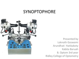
- 1. SYNOPTOPHORE Presented by Loknath Goswami Arundhati Hatikakoty Kabita Baruah B. Optom 3rd year Ridley College of Optometry
- 2. Presentation layout • History • Introduction • Principle • Models • Parts and slides • Uses • Advantages and disadvantages • Revision
- 3. History In 20th century, Claud Worth designed the Worth-Black amblyoscope which was later modified by H. M. Black Claud Worth
- 4. History 1914- Ettles made a stand amblyoscope, the Synoptophore, to overcome the clumsiness of the Worth instrument.
- 5. History 1930- Green patented his own Synoptophore , introducing a set of slides. It has been the basis of numerous sets of Synoptophore slides that followed Moorfields synoptophore Clement Clarke’s major synoptophore
- 6. INTRODUCTION • An instrument for diagnosing imbalance of eye muscles and treating them by orthoptic methods • An instrument used in orthoptic to present to the subject images at different angles of convergence or divergence so that the fusional ability can be tested Syn Opto phore Both Eye Range
- 7. Principle • Haploscopic principle • Synoptophores are designed on the principle of division of “physical space” into two separate areas of “visual space” each of which is visible to one eye only.
- 8. Principle • The object and its image are “conjugate”, being join by the optical system so that if test- object pictures are placed in a choosen position relative to each other it follows that the image will be directed into similar relative positions • By altering the position of the test objects in an instrument that their image can be made to stimulate selected retinal areas as required
- 9. Optics • A ray of light from the picture at P strikes the mirror at O, is reflected in the direction of OD and appears to come from a point X, at a distance behind the mirror equal to OP
- 10. Optics • The eye piece contains a convex lens D whose focal distance is DX = (DO + OP) • The image of the test object slide is therefore situated at the principle focus of the lens • Rays of light emanating from the principle focus will, after refraction by the lens D in the eye-piece, emerge as parallel rays; this means that an eye when viewing the image is relaxed or focused for distance, no accommodation being required
- 11. The Major Synoptophore Model 2051 • In addition to measuring deviation and management of binocular vision function, there are provisions for afterimages, automatic flashing and haidinger’s brushes • 2051 is the most comprehensive one with all the above mentioned additions
- 13. Model 2052 • This synoptophore resembles model 2051, with the exception that the haidinger’s Brush device is not included • The automatic flashing unit is precisely the same but instead of being attached to the base of the instrument it is housed in a well in the table • The after-image device is the same as that in model 2051
- 15. Model 2053 • This is the basic model synoptophore • It has all the features of Models 2051 and 2052 except the Haidinger’s brush, after- image and automatic flashing devices
- 17. Model 2051 • The base of the instrument contains the electrical components and controls needed for operation, including the transformer for reducing the mains current to the required low level • A voltage selector enables the synoptophore to be used on any A.C. current
- 18. Model 2051 • Rising from the base are two columns each of which supports an optical tube
- 19. Model 2051 • The two optical tubes each contain – A low intensity light source for the illumination of slides – A high intensity light source for creating after-images and Haidinger’s brushes – A slide carrier, with a plastics diffusing screen – An iris diaphragm for reducing the field of vision when Haidinger’s brushes are used – A reflecting mirror and an eyepiece lens of +6.50 D sph
- 20. Model 2051 • The slide carrier is situated at the focal point of the eyepiece lens, thus parallel rays of light emerge which should ensure relaxation of the patient’s accommodation • Accommodation can be induced by the introduction of minus lenses, placed in the lens holders which are situated in front of the eyepiece lenses
- 21. Model 2051 • The optical tubes can be adjusted by means of controls so that the distance between the centres of the eye-piece lenses and the patient’s IPD are the same
- 22. Model 2051 • The horizontal angle between the optical tubes can be increased or decreased by moving the handles which are sloped downwards so that even the smallest child is able to grip them comfortably
- 23. Model 2051 • The tube-lock together with the central lock allow vergence exercises to be given, so that each eye slowly converges, or diverges, to an equal extent
- 24. Model 2051 • The angles through which the tubes are moved are recorded in degrees on the outer edge and in prism diopters on the inner edge of the scales
- 25. Model 2051 • The slide carriers can be moved upwards or downwards to the extent of 10 pd by the controls, and vertical deviations and vergences are recorded on scales.
- 26. Model 2051 • If it is necessary to measure a vertical deviation greater than 10pd the elevation and depression controls may be used to augment the movement
- 27. Model 2051 • Torsional deviation is measured and corrected by operating one or other the controls, the effect of which is to rotate the slide carrier around the optical axis of the tube • Rotation of 20 degrees on either side of zero is obtainable and is recorded on the scales
- 28. Model 2051 • On the base of the instrument there are two rheostats • These enable the illumination of each slide to be varied
- 29. Model 2051 • When examining patients shortly after operation it may be desirable to reduce the luminousity of one or both lamps on account of photophobia; and when examining or treating amblyopes it may be advisable to increase the illumination in front of the amblyopic eye and reduce it infront of the other eye
- 30. Model 2051 • The two buttons are microswitches each of which when depressed, extinguishes the lamp, illuminating the ipsilateral slide. This device avoids the necessity of covering one eye in order to detect ocular movement when measuring the angle of deviation objectively
- 31. Model 2051 • A rotary switch on the base operates each of after-image lamps in turn and the slide illumination lamps are automatically extinguished whilst the test is carried out
- 32. Model 2051 • In order to maintain the after-image for a period of time and to use them in treatment of abnormal retinal correspondence it is necessary to provide the patient with an alternate light and dark background • One or both of the tubes can be intermittently illuminated • If both tubes are intermittently illuminated the period of illumination may be simultaneous or alternating
- 33. Model 2051 • A variety of speeds and different lengths of light and dark phase can be produced by manipulating the various controls on the flashing unit • Thus variations can be made are:
- 34. Model 2051 1. Simultaneous flashing: both lamps flashing for the same sequence of light and dark, the periods of light and dark being variable 2. Alternate flashing: in which the period of light in one slide carrier coincides with a period of dark in the other, and vice versa 3. One lamp flashing according to the light and dark setting, whilst the other lamp is extinguished 4. One lamp flashing variably according to dial setting whilst the other remain illuminated continuously
- 35. SLIDES USED IN SYNOPTOPHORE
- 36. SLIDES • SIMULTANEOUS PERCEPTION SLIDES – • These are two dissimilar slides of two different pictures which can be overlapped • Each slide is presented separately to each eye • Each slide size has been calculated to subtend a different angle at the nodal point of the eye • These are graded into 3 groups by their size 1) Foveal 2) Macular 3) Paramacular
- 37. 1) Foveal- • These slides have small sized pictures • They do not exceed the size of the fovea • Foveal slide- 1° 2) Macular- • They have pictures slightly larger than the foveal slides • Macular slide 1-3° 3) Paramacular- • They have the largest pictures that extends into paramacular areas • Paramacular slide 1-5°
- 38. Some of the simultaneous perception slides are:
- 39. Some of the simultaneous perception slides are:
- 40. Some of the simultaneous perception slides are:
- 41. Some of the simultaneous perception slides are:
- 42. FUSION SLIDES • Consists of two dissimilar pictures each of which is incomplete in each details. For ex- two rabbits each lacking a tail or a bunch of flowers • If there is presence of fusion in a patient then he will see the complete image of the rabbit holding a bunch of flowers • In the presence of suppression either tail or bunch of flowers will be missing
- 43. Some of the fusional slides are:
- 44. Some of the fusional slides are:
- 45. Some of the fusional slides are:
- 46. Some of the fusional slides are:
- 47. STEREOPSIS SLIDES • Consisting of two pairs of same objects hypothetically taken from slightly different angles to indicate depth perception • These slides are inserted into the slide holders with the controls of each slide positioned towards or away from the subject. • The patient is then required to describe the apparent effect
- 48. Some of the slides used for stereopsis testing are:
- 49. Some of the slides used for stereopsis testing are:
- 50. Some of the slides used for stereopsis testing are:
- 51. Some of the slides used for stereopsis testing are:
- 52. SPECIAL PURPOSE SLIDES • These special purpose slides are used to assess Abnormal Retinal Correspondance(ARC). • Using the illumination settings on Synoptophore, horizontal and vertical alignment can be achieved in the presence of steady foveal fixation • These are graded into 3 groups
- 53. AFTER IMAGE SLIDE • Horizontal streak and one vertical streak, each with central red fixation mark
- 54. Slides with numbers and letters
- 55. HAIDINGER BRUSHES • Haidinger brushes are an entoptic phenomenon seen only at the fovea • It is produced by viewing a revolving polarised light through a blue filter
- 57. Diagnostic • Measurement of deviation – With each eye fixing (Paralytic squints) – Objective angle and subjective angle (ARC) – In different gaze position (incomitant squints) – Horizontal, vertical and torsional deviations can be measured • Special functions as adaptability to function in aniseikonia with help of special slides • “After image” testing
- 58. Diagnostic • Assessment of binocular status: – Simultaneous macular perception – Fusion – Stereopsis • For foveal, macular and paramacular retinal areas • Measurement of range of fusion • Cases with incomplete suppression can also be tested by using differential illumination and by using flashing devices • Appreciation of entoptic phenomena, Haidinger brushes
- 59. Therapeutic • Fusional vergence exercises • Management of suppression-antisuppression exercises • Treatment of anomalous retinal correspondence • Amblyopia therapy with the help of Haidinger brushes
- 61. Advantages • Accurate measurement is possible • Tube can move separately • Large selection of suitable slides are available • The patient’s eye can be seen by the examiner and the corneal reflections can be observed. • There can be rapid interchange from objective to subjective conditions
- 62. Disadvantages • Not useful in non cooperative child • Bulky instrument, difficult to transfer from one place to other. • Though the slides are kept in optical infinity distance but still it stimulates proximal accommodation of the patient. • Needs skill to handle the instrument accurately.
- 63. 1) Optical tube 2) Chin rest 3) Head rest 4) Handles for adjustments of horizontal angles between the tubes 5) Scales for measuring horizontal deviations 8) Slide carrier 11) IPD controls Parts of Synoptophore
- 64. 6) Central lock 7) Horizontal vergence scale 9) Vertical controls 10) Vertical deviation scales 12) Chin rest controls 13) Torsional deviation controls 14) Elevation depression controls 15) Elevation depression scales 16) Light and dark phase controls 17) Rapid and variable switch 18) Speed controls 19) Lamp housing Parts of Synoptophore
- 65. 20) Horizontal vergence controls 21) Selector switch 22) Hand flashing switch 23) Dimming rheostats 24) Horizontal tube locks 25) Simultaneous/ alternating switch 26) Torsional deviational scales 27) IPD scales 28) Mains 29) on/off switches(haidinger’s brushes) 30) Reversing switch Parts of Synoptophore
- 66. References • Lyle and Jackson’s, Practical opthoptics in the treatment of squint, 5th edition, page no. 96-105 • Pradeep Sharma, Strabismus simplified, page no. 211-13 • https://www.merriam- webster.com/medical/synoptophore • http://medical- dictionary.thefreedictionary.com/synoptophore
Editor's Notes
- It was one of the first instruments used to examine and exercise the faculty of binocular vision. Its basic construction is retained to the present day in the modern major synoptophore and synoptiscope
- AMBLYOSCOPE is used for training the fusion power. In Britain known as synoptophore, but in USA as troposkop.
- When the optical tubes are rotated they move around the centre of rotation of the eyes, enabling the patient to follow the images through a large angle It is necessary to position the patient’s eyes correctly by accurate adjustment of the chin rest, the headrest and the IPD
- By releasing the central lock the two tubes can be swung from side to side to give lateral movements whilst the tube being locked together are maintained at a constant angle. The amount of vergence is recorded on the scale in degrees
- These controls rotate the optical tubes about the centre of rotation of the patient’s eyes, and the movement is recorded in degrees on scales. If both controls be used in conjunction with one another the degrees of deviation shown on the scales should be converted in pd (by multiplying by the fraction 7/4) and added to the deviation in pd shown in the other scale
- It is also useful as a means of stimulation when suppression occurs, and it can be used to maintain after-images, although the automatic unit is provided for this purpose