1. Newsletter of Oceanic Consulting Corporation
Spring 2008
Lockheed Martin and VIKING Life-Saving Equipment
Norge AS have joined forces to provide a safer,
more efficient, and cost-effective offshore Crew
Transfer System capable of operating in heavy
sea conditions. By combining Lockheed Martin's
advanced hullform designs with VIKING Life-Saving
Equipment Norge's patented embarkation systems,
offshore platform operators will be able to quickly
and safely transport their work crews in all weather
conditions.
Continued on page 3...
EVALUATION OF A NEW SEA BORNE
CREW TRANSFER SYSTEM DESIGN
• Evaluation of a New Sea Borne
Crew Transfer System Design
• Charting the Course: Spring 2008
• Hydrodynamic Study of VIV
Suppression Devices on a Rotating
Drill String
• NRC Institute for Ocean Technology-
Ocean Energy Update
• Evaluation of the MINIFLOAT III
Platform
• Detailed Evaluation of an Ice-
Strengthened Coastal Ferry
• Profile: Carl J. Harris
• Feature: Offshore Engineering Basin
In this issue...
newsletter.qxp 5/1/08 10:36 AM Page 1
2. J. Michael Doucet
Senior Naval Architect
Consultant, Ship Performance
michael_doucet@oceaniccorp.com
Paul Herrington
Senior Naval Architect
Consultant, Offshore Systems
paul_herrington@oceaniccorp.com
Tim Moore
Senior Mechanical Engineer
Consultant, Ships and Systems Performance
tim_moore@oceaniccorp.com
SPRING2008
CHARTING THE COURSE
gives me great pride to announce that Oceanic Consulting
Corporation is celebrating 15 years of Commercial Research
and Development in 2008.
Established in 1993 as Marineering Limited, the firm has become
a worldwide leader in commercial research and development in
hydrodynamics and Arctic engineering. Oceanic’s business model
is to use public sector research facilities based in St. John’s at the
National Research Council of Canada and Memorial University as a
unique selling proposition in providing hydrodynamic services to the
global marine industry. In 1998, to mark greater integration locally
and to allow for better brand differentiation internationally, the firm
began operating under the Oceanic name.
Internationally recognized for its expertise in the areas of vortex
induced vibration (VIV) research, Arctic and ice engineering, commercial shipping, and its work for
clients competing in the America’s Cup, including two-time champion Team Alinghi, Oceanic also
has carried out research for a wide range of projects, including liquefied natural gas carriers, semi-
submersible drilling units, production spars, floating production storage and offloading vessels,
articulated tugs & barges, and a number of super yachts.
As company founder and president, I believe that the firm’s success is due to its experienced group
of researchers, engineers, and technical personnel; everyday I witness the tremendous dedication
and teamwork of everyone in our company. This, combined with its access to one of the world’s most
comprehensive collections of hydrodynamic research facilities, is what makes Oceanic a world leader
in commercial research and development. For the past 15 years, Oceanic’s mission has been to
provide clients with the expertise, sophisticated facilities, and technology to realize even the most
ambitious projects. We remain committed to this mission for the next 15 years and beyond.
To mark this anniversary, Oceanic has many exciting plans in development including a website
re-launch, new company promotional material, and new partnerships. I invite you to see us at
the Offshore Technology Conference in Houston for updates.
As a last word, I would like to take the opportunity to thank all the readers of our newsletter, Making
Waves, clients past and present, our employees, and to all of those who have given support, advice,
and kind wishes to our company over the last 15 years. Each contribution has helped make Oceanic
Consulting Corporation the success it is today.
For Oceanic Consulting Corporation,
and with best regards,
Dan Walker, Ph.D., P.Eng.
President
For additional details on any of the projects highlighted in this edition, please contact:
ItIt
3
4
5
6
Lee Hedd
Vice President
Business Development
lee_hedd@oceaniccorp.com
Don Spencer
Vice President
Technical Development
don_spencer@oceaniccorp.com
newsletter.qxp 5/1/08 10:36 AM Page 2
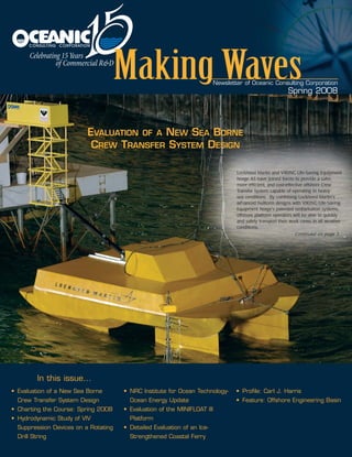
3. Continued from cover...
Lockheed Martin's SLICE® vessel design and
VIKING Life-Saving Equipment Norge's newest
generation of Selstair will be linked to form
an innovative new transfer system. Selstair
features a collapsible staircase capable of being
lowered to a convenient height in order to
allow safe, controlled, and convenient access
to a waiting vessel. The new transfer system
will make it easier for platform workers,
maintenance crews, and others to move safely
between the transport vessel and the offshore
platform in less time than current maritime
methods and at less cost than helicopter
transport.
Oceanic was contracted by Lockheed Martin to
provide the physical evaluation program of this
proposed Crew Transfer System. The intent of
the model tests was to quantify the degree of
motion that would occur between the
component systems with the ship operating in
a seaway of up to Sea State 5. As the system
will be used for the embarkation and
debarkation of work crews, the motions of the
system must fall within acceptable ergonomic
limits for the crew members actively transferring
to or from the platform. As well, the motions
of the transfer vessel at zero-speed must be
comfortable for the workers that would be on
board and awaiting rotation.
For this program, Oceanic built for VIKING Life-
Saving Equipment Norge a 1:10 scale model
of their Selstair retractable ladder system.
The stair system consists of several platforms
connected with flexible elements. Each
component (platforms and stairs) and the
flexible linkages of the Selstair were modeled
to provide the correct dimensional, mass and
inertial properties. Also modeled accurately
was the underwater stabilization frame.
The entire crew transfer system, consisting of
the VIKING Selstair model, and models of the
Lockheed Martin designed gang-way (dubbed
the Crew Embarkation Way or CEWay™) and the
Lockheed Martin SLICE® Crew Transfer Vessel
(SCTV), were extensively tested in waves of
up to Sea State 5 to assess the interactions of
the three primary components of the system.
In addition to the question of ergonomics,
another project goal was to quantify the
lateral thrust required from the four tunnel
thrusters that provide the dynamic positioning
capability (DP2) for the ship. To provide this
information simply and economically, the model
was connected to linear mooring springs and
the mooring loads were measured during the
stationkeeping tests. Oceanic also conducted
resistance experiments on the SCTV model to
provide Lockheed Martin with powering
predictions for the vessel.
"Lockheed Martin is an innovator in developing
fast, stable hullforms, and VIKING Life-Saving
Equipment Norge is a world leader in developing
embarkation, evacuation and safety equipment
for the maritime industry," said Dan Schultz,
vice-president and general manager of Lockheed
Martin's Maritime Security & Ship Systems line
of business in Baltimore. "By coming together,
our two companies will provide a solution that
reduces the risk inherent in the transfer of
personnel between a ship at sea and an
offshore platform."
"Our success depends on a team effort, with
shared values and common goals," said Bjorn
Tormod Akselsen, managing director of VIKING
Life-Saving Equipment Norge. "Together we
are committed to raising safety standards and
determined to lead the way for a safer life at
sea."
Alex Boon of Lockheed Martin said, “We are
very pleased with the conduct of the test
program and with the performance of the
system in these tests.” Mr. Boon attended the
tests with other representatives of both Lockheed
Martin and VIKING Life-Saving Equipment.
Also attending the tests were representatives
of a major oil company who have shown interest
in the system for their offshore installations.
ance
OFFSHORESAFETY
3
EVALUATION OF A NEW SEA BORNE CREW TRANSFER SYSTEM DESIGN
SSLLIICCEE®® CCrreeww TTrraannssffeerr VVeesssseell wwiitthh SSeellssttaaiirr ssyysstteemm..
newsletter.qxp 5/1/08 10:36 AM Page 3
4. The Institute for Ocean Technology (IOT)
provides Canadian developers of ocean
energy extraction devices with the performance
evaluation tools required to develop their
concepts. These tools include numerical
simulation, physical modeling, and field trials.
Additional complementary and overlapping
expertise exists in other research organizations
across the country. Canada has a wealth of
ocean engineering knowledge that could be
focused on the needs of Canadian ocean
energy developers. IOT encourages
collaboration with these organizations to
benefit the Canadian ocean energy effort.
Currently, the Institute is working with several
Canadian ocean energy technology developers
to arrange model experiments in the IOT
facilities over the next several months.
The Offshore Engineering Basin, Towing Tank,
and Ice Tank can all be used to investigate
hydrodynamic issues affecting ocean energy
devices. The ocean energy development
process will typically involve many model-scale
experiments, as different issues are investigated
and concepts evolve. Development will also
iterate between laboratory tests and open
sea experiments. IOT has the expertise and
equipment to conduct long duration field trials
that gather both device and environmental data.
While the Institute’s main focus is on assisting
developers with technical issues, it is also an
active advocate for a concerted, national effort
towards the development of the Canadian
ocean technology industry. IOT staff regularly
participate in the workshops and symposia
organized by the Ocean Renewable Energy
Group (www.OREG.ca). OREG is a sector
association promoting ocean energy in
Canada, and IOT’s Director General is a
member of its board of directors.
The Institute also advises government and
regulatory bodies on their ocean energy
activities. IOT is represented on the International
Electro-technical Commission TC 114 National
Committee, and the NRCan Ad-hoc Ocean
Energy Technical Advisory Committee.
IOT also participated in the technical evaluation
of proposals for the Nova Scotia government’s
In-Stream Tidal Energy Demonstration Project.
The Institute was also involved in an ocean
energy technology screening report for
NRCan, and co-authored a report on the
presence of ice in the headwaters of the
Bay of Fundy.
As part of its internal research program, the
Institute is investigating the effect of scale when
modeling simple ocean energy devices. IOT
is also planning a project to compare numerical
and physical model results related to farm array
orientation of wave energy converters.
HYDRODYNAMICS
4
In August 2007, Oceanic Consulting Corporation
evaluated vortex induced vibration (VIV)
suppression fairings for GeoProber Drilling Ltd.
Three 15D triple helix strake models were
assessed, with strake heights representing 10,
15, and 20% of the shell diameter. The VIV
experiments were undertaken in four test
modes: (a) the typical fixed mode, with the
strake connected rigidly to a non-rotating pipe;
(b) the strake fixed to the pipe, and both
rotating; (c) the strake free to float and rotate
on a non-rotating pipe; and, (d) the strake free
to rotate on a rotating pipe.
A simple rope wound around the pipe and a
commercial dual fin fairing (ADFS) from AIMS
International were also evaluated; non-rotating
and rotating bare pipes were assessed to obtain
a baseline curve for comparison.
Oceanic’s small VIV rig was installed in the
90-meter Ice/Towing Tank at the National
Research Council’s Institute for Ocean
Technology. The test apparatus allowed for
vertical motion of a spring-mounted sub-frame
which was free to slide vertically on two rails
with linear circulating bearings.
A 3.5-inch aluminum pipe, with a 4-inch outer
diameter (102 millimeters) and a length of
3.42 meters giving an aspect ratio of 34, was
selected for testing. The pipe was mounted
on an axle through its center, with ball bearings
at each end. A servomotor was connected to
the pipe through a chain drive and a torque
dynamometer. For some tests, the pipe was
rotated at speeds up to 200 rpm. The strakes
were either rigidly connected to the pipe
or free to rotate with it. Similar tests were
conducted with a stationary pipe.
A bare rotating pipe showed suppression of
VIV; however, the addition of strakes did not
demonstrate any significant benefit. The ADFS
units were very effective in reducing VIV and
had low drag. The addition of a simple rope to
the bare rotating pipe showed promise; however,
further work is needed to determine the specific
function of the rope. A surprising finding was
that there may be a point where the size of the
strake and the reduced velocity may lower the
driving torque to zero or may even change
sign. In conjunction with these experiments,
an extensive Particle Velocimetry Imaging
program was conducted by Memorial
University researcher Jie Xu (results reported
in OMAE 2008) and included cases with bare
pipe, rotating bare pipe, strakes, and ADFS
fairings.
HYDRODYNAMIC STUDY OF VIV SUPPRESSION
DEVICES ON A ROTATING DRILL STRING
SSttrraakkee mmooddeell iinnssttaalllleedd oonn VVIIVV tteesstt rriigg..
NRC INSTITUTE FOR OCEAN TECHNOLOGY - OCEAN ENERGY UPDATE
newsletter.qxp 5/1/08 10:37 AM Page 4
5. Marine Innovation and Technology (MI&T) of
Berkeley, California, contracted Oceanic to study
the hydrodynamic interaction of waves and
current with the platform water-entrapment
plates on its MINIFLOAT III platform. Model
evaluations were carried out in Memorial
University’s Ocean Engineering Research
Centre’s 58-meter Towing Tank in St. John’s.
The 1:80 scale acrylic model platform was
built by MI&T and was evaluated in head
and following seas for a fully loaded
configuration with an 85-foot draft. From the
results produced by Oceanic, MI&T was able
to make various conclusions concerning the
performance of MINIFLOAT III.
System identification tests validated the model
and mooring arrangement against target values.
Tow tests showed that the drag coefficient,
based on the projected underwater area of
the hull, was 1.1 and MI&T concluded that
vortex induced motions (VIM) were not
significant. The model was then evaluated in
regular waves with two different wave heights
for periods ranging from 8 to 28 seconds.
The pitch, and to a lesser extent the heave
responses, showed small non-linear variations
with wave height. Particular attention was given
to vortex-shedding and hydrodynamic lift effects
in regular wave tests due to the interaction of
waves and current with the platform water-
entrapment plates. The tests were repeated with
two towing speeds and after imposing a positive
and negative 3.5º static trim angle to the model.
The Response Amplitude Operators (RAOs)
showed no significant variations in the surge
or heave responses, but more significant effects
of the mean trim angles were apparent in the
pitch RAO for periods between 10 and 25
seconds. These effects came from the static trim
angle and were independent of forward speed.
Drag coefficient variations around the edges
of the water-entrapment plates, rather than
lift effects, explain this behaviour.
A small sinkage component
increased with forward speed
and reduced with platform
heave (or wave period).
This component was
independent of the
model’s angle of attack
(trim), and,
therefore, was
not related to
lift. It was,
however,
associated with
the effect of
higher pressures
above the water-
entrapment plate
due to the
presence of the
columns.
The 100-year
hurricane Sea
State was
examined
with forward
speed to
model the
effects of the
current. In this
case, a weight
and pulley system modeled the mean current
force and wind force. The 100-year three-hour-
long wave train had a significant height of
46 feet and a peak period of 14.6 seconds.
Forward speed runs lasted 30 minutes in full
scale. These experiments, which were repeated
four times, exposed the model to two hours of
the three-hour-long Sea State, including the
most significant wave events. The 100-year
results showed a maximum pitch below 10º,
a maximum heave below 20 feet, and a
maximum offset of 3.1% of the 7,000-foot
water depth.
A comparison of the motion spectrum both with
and without forward speed showed a significant
increase in low frequency horizontal motion
due to forward speed. Forward speed also
increased the low-frequency resonant pitch,
but reduced the first-order wave induced pitch.
Similarly, first-order wave-induced heave was
smaller with forward speed, partly due to a
shift in the encounter period.
The difference in results with and without
carriage velocity was also significant. The
maximum relative wave height was almost
10 feet higher with forward speed. This was
consistent with the observations that the
Doppler effect decreased the peak period
when the carriage moved. This, in turn,
led to a larger wave crest at the platform
mean waterline. The current increased
platform sinkage and increased maximum
pitch. As a result, the clearance between the
wave crest and the deck was reduced.
OFFSHOREINNOVATION
5
EVALUATION OF THE MINIFLOAT III PLATFORM
MMoooorriinngg sseett--uupp ffoorr tthhee MMIINNIIFFLLOOAATT IIIIII ppllaattffoorrmm..
newsletter.qxp 5/1/08 10:37 AM Page 5
6. COMPREHENSIVEEVALUATION
In 2007, Oceanic Consulting Corporation was
contracted by Poseidon Marine Consultants
Limited (PMC) to evaluate different hull and
propulsion configurations for a 16-car RO/RO
ferry design. Designed under a “Safe Ferry”
concept, PMC intended to maximize aspects of
stability, accessibility, functionality, and
environmental stewardship. The overall goal of
this evaluation project was to provide supporting
information that could aid in optimizing the final
design of this vessel, and, where possible, to
gather knowledge that could be applied to
future ferry designs created in accordance
with the established “Safe Ferry” principles.
The ferry, which is being designed by PMC for
the Department of Transportation and Works
of the government of Newfoundland and
Labrador, will operate year-round in the
coastal waters of the province.
Given the province’s location, its northern
coastal waters are exposed to varying ice
conditions in the spring and harsh North
Atlantic wave conditions at any time of the
year. To assess vessel design options
identified by PMC during the initial design
process for these wide-ranging environmental
conditions, Oceanic devised a broad evaluation
program encompassing both physical tests and
numerical assessments.
Various bow geometries were considered to
ensure that the ferry could operate effectively
in ice. However, as ice may be experienced for
only a few months each year, it was essential
that open water performance not be
compromised. The propulsion arrangement
for this twin-screw vessel was also under
consideration. Both right-angle drives (RADs)
and traditional shafting arrangements were in
contention. The former was desirable because
of the increased vessel maneuverability that
would be achieved, while the latter was
considered because the inclusion of RADs on
this particular hull design might not be well
suited to operation in ice. Also, given the
vessel’s small size, it was desirable to ensure
that the selected hull options would permit the
vessel to have acceptable seakeeping
characteristics in order to provide
passengers with comfortable transportation.
At the outset, PMC devised various preliminary
hullforms for consideration. Oceanic reviewed
the lines and provided comments and
recommendations on both the hydrodynamic
performance and the performance in ice of the
candidate hulls. Based on PMC’s revised lines,
four candidate hulls were examined using a
CFD (Computational Fluid Dynamics) code to
assess wave-making resistance. From this
analysis, one hull was discounted immediately
as it was clearly shown to have higher resistance
than the other candidates. Most importantly,
the ice-clearing bow, which was intended to
optimize performance in ice, did not appear
to be detrimental to open water performance.
Thus, by using the CFD results, it was possible
to narrow the field of candidate hulls to be
examined during physical model testing.
Two distinct phases were considered in the
physical test program: the first examined
operation in ice while the second assessed
performance in open water. At a scale of
1:10.5, the hull models for the 42-meter ship
were constructed with interchangeable bow
and stern sections so that four different hull
configurations could be created.
Three appended hull configurations were
evaluated in ice. Testing included resistance
in level ice, self-propulsion in ice, and backing
in pack ice. The ice was modeled to match
thin first-year or land-fast ice that would be
experienced on the north-east coast of
Newfoundland. Using both under- and above-
water video cameras made it possible to study
the ice movement around and under the
models. These qualitative observations
allowed additional recommendations to be
made concerning local stern modifications
that would further improve ice-clearing when
backing. The test results showed that the
performance of the RAD units would be
acceptable in ice, with little possibility of ice
blockages occurring. PMC concluded that it
would not be necessary to continue evaluation
of the traditional shaft-driven propulsion
arrangement. The quantitative results also
showed that the ice-clearing bow provided
superior performance in ice, resulting in over
20% less resistance at a speed of 4 knots in ice.
For the remaining tests in open water, the stern
with RAD propulsion was evaluated with the
two alternative bow geometries: the
conventional bow and the ice-clearing bow.
Open water tests included flow visualization of
the underwater hull, calm water resistance, self-
propulsion, lost speed in head seas, and head
seas seakeeping. In this phase of testing, it
was necessary to ascertain if the desirable ice-
clearing bow would provide adequate open
water performance. At a transit speed of 11
knots, the ice-clearing bow did in fact provide
improved performance, with calm water
resistance being approximately 6% less than
DETAILED EVALUATION OF AN ICE-STRENGTHENED COASTAL FERRY
RReennddeerreedd iimmaaggee ooff tthhee 1166--ccaarr RROO//RROO ffeerrrryy..
6
MMooddeell dduurriinngg rreessiissttaannccee eevvaalluuaattiioonnss..
newsletter.qxp 5/1/08 10:37 AM Page 6
7. that of the conventional bow. To aid in engine
selection, powering requirements were
quantified from the self-propulsion tests.
At this point in the program, the ice-clearing
bow seemed to be a clear winner, with only
seakeeping performance still in question. From
the head seas tests, conducted in an upper-end
Sea State 4 condition, the conventional bow
was shown to provide slightly less lost speed in
waves. As this difference was only on the order
of a few percent, the margin was not sufficient
to warrant selection of the conventional bow for
the final design. The motion and acceleration
characteristics with either bow were virtually
identical.
To provide more in-depth knowledge of the
seakeeping characteristics of the vessel, a
range of sea states, vessel speeds, and headings
were examined with Oceanic’s panel method
seakeeping code MOTSIM. Using this time-
domain code, vessel performance was assessed,
both with and without bilge keels, for each bow
configuration. The results demonstrated that
the ice-clearing bow had no detrimental effects
on the ferry’s seakeeping performance. Given
the small size of the vessel, this assessment
clearly illustrated the need for bilge keels and
the additional roll damping that would be
afforded by their inclusion.
Local accelerations were also determined for
the center of gravity, the Bridge Wing, and the
Passenger Lounge so that a habitability analysis
could be completed. This analysis provided a
useful measure of passenger and crew comfort,
and indicated particular speed and heading
combinations that should be avoided in order
to minimize exposure to conditions that could
lead to motion sickness and crew fatigue.
Finally, as physical maneuvering tests were
beyond the scope of the project, a numerical
assessment provided an indication of
the vessel’s maneuvering performance.
Empirical methods were used to
estimate the vessel’s non-dimensional
maneuvering coefficients and
simulations using Oceanic’s
maneuvering code SML (Ship
Maneuvering Laboratory) examined
various standard maneuvers including
turning circles, crash stops, and
zig-zags. The results, which were
compared against relevant IMO
(International Maritime Organization)
maneuverability criteria, showed that
vessel maneuverability would be
adequate for this design.
This comprehensive evaluation program
successfully assessed the design and
guided PMC in their selection of the final ship
parameters. Detailed design is progressing
and expectations are that multiple vessels will
be built. The construction contract will be
awarded in the near future. Oceanic is pleased
to have been involved with so many aspects of
this project and wishes success to both Poseidon
Marine Consultants Limited and the government
of Newfoundland and Labrador, Department of
Transportation and Works as they continue their
work on the project.
Oceanic congratulates Carl J. Harris on his
appointment as Director of Facilities at the
National Research Council’s Institute for
Ocean Technology in St. John’s, NL.
Mr. Harris has a broad background in
experimental hydrodynamics and is a
regional expert in numerical modeling
capability. His appointment brings
complementary strengths to the local
marine community by advancing the
science behind the art of simulation.
Mr. Harris has built his career around refining
physical experiments to provide optimum data
and quality at minimum expense. He began
his research at the National Research Council
(NRC) in 1986; there he implemented efficiency
methods in the Towing Tank facility and
developed original equipment and techniques
for America’s Cup Sailing Yacht testing.
In 1995, Mr. Harris left NRC to help form
Marineering Limited, now Oceanic Consulting
Corporation. As a senior partner and Vice
President, Mr. Harris was responsible for the
growth of the company’s technical capability
and for coordinating project schedules, staff
allocations, and facility liaisons. This experience
led Mr. Harris to Memorial University where he
worked with the Centre for Sustainable Aquatic
Resources from 2001 to 2004 and the Centre
for Marine Simulation (CMS) from 2004 to
2007. At CMS, Mr. Harris established
a numerical ship-modeling capability which
has allowed the Centre to compete in the
growing international market for
simulation/evaluation services. In February
2008, Mr. Harris re-joined NRC where he
now oversees the Institute’s testing facilities
and infrastructure.
Mr. Harris is a Professional Engineer and
received both his Bachelor’s (1986) and
Master’s (1993) degrees in Engineering
(Ocean and Naval Architecture) from
Memorial University. He is also a member
of the Professional Engineers and Geoscientists
of Newfoundland and Labrador (PEG-NL).
Mr. Harris has written and co-authored
numerous articles on investigative
hydrodynamics and has been a featured
speaker at several conferences, including
Ocean Innovation 2007.
PROFILE
PROFILE: CARL J. HARRIS
COASTAL FERRY CONTINUED
MMrr.. CCaarrll JJ.. HHaarrrriiss..
WWaavvee ccoonnttoouurrss aatt 1111 kknnoottss..
7
newsletter.qxp 5/1/08 10:37 AM Page 7
8. • Offshore Engineering Basin • 200-meter Wave/Towing Tank
• 58-meter Wave/Towing Tank • 90-meter Ice/Towing Tank
• Cavitation Tunnel • 22-meter Flume Tank
• Centre for Marine Simulation • VIV Test Apparatus • MOTSIM
Specification sheets can be obtained from the Oceanic website
or by contacting our office.
Offshore Engineering Basin Specifications:
95 Bonaventure Ave., Suite 401
St. John’s, NL
Canada A1B 2X5
Telephone 709 722 9060
Facsimile 709 722 9064
Email oceanic@oceaniccorp.com
www.oceaniccorp.com
ISO 9001-2000
Specification Sheets are Available for
All Major Facilities, Including:
Meet us at:
October 15-17
Houston, TX
July 20-23
Banff, Alberta
December 3-5
New Orleans, LA
Length 75 m
Width 32 m
Max. Water Depth 3.2 m
Wave Making System (Power) 1800 kW
Max. Wave Height (Regular Waves) 1 m
Sig. Wave Height (Irregular Waves) 0.5 m
Wave Lengths 0.5 m to 20 m
Articulation of Waves (Modes) Flapper, Piston, Combination
Wave Spectra Regular, Irregular, Bi-modal, Multi-directional
Current Speed Water-depth Dependent (0.5 m/sec at 1 m depth; 0.25 m/sec
at 2 m depth; 0.2 m/sec at 2.8 m depth)
Average Wind Velocity 11 m/sec at 1 m from Fan, 5 m/sec at 5 m from Fan
Turbulent Wind Spectrum Mean Speed 12 m/sec
Wind Spectra American Petroleum Institute Standard, Norwegian Petroleum
Directorate Standard, Other Industry Standards
Optical Tracking System Accuracy ±1 mm Moored Models, ±5 mm Free-running Models
Applications
• Testing of Moored Floating Systems or Gravity-based Structures in Wind, Waves, and Current
• Testing of Free-running and Self-propelled Ship Models
Tests Performed
• Seakeeping
• Maneuvering
• Wave Energy Conversion
• Wave Impact Loads on Ships or Offshore Structures
• Tow-out, Set Down, and Operation of Offshore Structures
• Mooring/Riser Evaluations
May 13 & 14
Stamford, CT
newsletter.qxp 5/1/08 10:37 AM Page 8