The Most Attractive Pune Call Girls Budhwar Peth 8250192130 Will You Miss Thi...
34866616-Relay.ppt
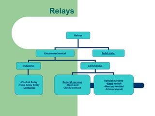
1. Relays
Electromechanical Solid state
Industrial Commercial
-Control Relay
-Time delay Relay
-Contactor
General purpose
-Open and
Closed contact
Special purpose
-Reed switch
-Mercury wetted
-Printed circuit
Relays
2. Build & Operation Of
Electromechanical Relay
Relays are devices that operate as an
electrical switch, opening and closing under
electromagnetic conditions.
A relay is a simple electro-mechanical switch
made up of an electromagnet and solenoid
with a set of contacts.
Usually known as control relay
3. Relays function
Two primary functions;
Relay can control large current/voltage with small
electrical signal because relay coils require low
current/voltage to switch but can energizes large
currents or voltages. The structure of relay itself
allows the dc control source at the safe distance
from such ac load
Isolation of the power used to control the action from
the power that must be switch to cause some action
5. Explanation
A switch is controlling power to the electromagnet.
When the switch is on, the electromagnet is on, and
it attracts the armature. The armature is acting as a
switch in the second circuit.
When the electromagnet is energized, the armature
completes the second circuit and the light is on.
When the electromagnet is not energized, the spring
pulls the armature away and the circuit is not
complete. In that case, the light is dark.
6. Electromechanical Relay
Construction and
Operation:
Only have two states of
operation: ON and OFF.
Consists four main parts:
Solenoid: coil and
magnetic core
Armature
Spring
Set of Contacts
7. Relays Operation
When electric current passes through a coil, magnetic north and south
pole are produced across the gap separating the coil and armature,
acting like an electromagnet.
The magnetic field ‘pull in’ the armature and close the contact NC(
Normally close contact), to NO (Normally close contact) . When the
electrical current stops flowing, the armature return back to normal
position
Relay actuated whenever sufficient current intensity produced enough
force to overcome spring tension.
11. Relay control circuit
In the figure below, a relatively small switch 24Volt DC source across
the coil of the relay located at the site of the load. When relay coil is
energized, the contacts switch the large voltage and current to the
load. The control voltage is DC, and controlled voltage is AC, with both
source and grounds isolates from each other. Contacts are insulated
from relay frame and coil as shown is figure.
12. Relay Rating & Configurations
The voltage and power type (AC or DC) the coil needs to operate ; that
is 12Vdc, 24Vdc and 110Vac.
Relays allow one circuit to switch a second circuit which can be
completely separate from the first. For example a low voltage battery
circuit can use a relay to switch a 480 VAC mains circuit.
There is no electrical connection inside the relay between the two
circuits, the link is magnetic and mechanical.
The coil does not have to work on the same voltage as the voltage
being sent over the high power contacts. There is no need to send
high voltage to the small switch.
13. Relay Rating & Configurations
When you purchase relays, you generally have
control over several variables:
Physical size and pin arrangement
If you are choosing a relay for an existing PCB you will need
to ensure that its dimensions and pin arrangement are
suitable. You should find this information in the supplier's
catalogue.
Coil voltage
The relay's coil voltage rating and resistance must suit the
circuit powering the relay coil. Many relays have a coil rated
for a 12V supply but 5V and 24V relays are also readily
available. Some relays operate perfectly well with a supply
voltage which is a little lower than their rated value.
14. Relay Rating & Configurations
Coil resistance
The circuit must be able to supply the current required by the relay coil. You can
use Ohm's law to calculate the current:
Relay coil current = supply voltage
coil resistance
For example: A 12V supply relay with a coil resistance of 400 passes a current
of 30mA. This is OK for a 555 timer IC (maximum output current 200mA), but it
is too much for most ICs and they will require a transistor to amplify the current.
Switch ratings (voltage and current)
The relay's switch contacts must be suitable for the circuit they are to control.
You will need to check the voltage and current ratings. Note that the voltage
rating is usually higher for AC, for example: "5A at 24V DC or 125V AC".
Switch contact arrangement (SPDT, DPDT etc)
Most relays are SPDT or DPDT which are often described as "single pole
changeover" (SPCO) or "double pole changeover" (DPCO).
15. Relay Specification
The standard voltage for relay used in machine
control is 120 volt.
The coils on electromechanical devices such as
relays, contactors and motor starters are designed
so as not to drop out (de-energize) until the voltage
drops to minimum of 85% of the rated voltage.
The relay coils also will not pick up (energize) until
the voltage rises to 85% of the rated voltage. This
voltage level is set by the National Electrical
Manufacturer Association (NEMA).
16. Relays Advantages & Disadvantages
Advantages Disadvantages
1. Relays can switch AC and DC, transistors
can only switch DC.
1. Relays are bulkier than transistors for
switching small currents.
2. Relays can switch high voltages,
transistors cannot
2. Relays cannot switch rapidly (except
reed relays), transistors can switch many
times per second.
3. Relays are a better choice for switching
large currents (> 5A).
3. Relays use more power due to the
current flowing through their coil.
4. Relays can switch many contacts at once 4. Relays require more current than many
chips can provide, so a low power transistor
may be needed to switch the current for the
relay's coil.
17. APPLICATION OF RELAYS IN
INDUSTRIES
Relays are used in the control of fluid power
valves and in many machine sequence
controls such as boring, drilling, milling and
grinding operations.
19. The switch logic circuit application in
relay
The switch logic circuit application in relay shows a relay with two NO
contacts. One contact is used as an interlock around the START push
button. Thus, an interlock circuit is a path provided for electrical energy to
the load after the initial path has been opened. The second relay contact is
used to energize a light. Remember that when a relay coil is energized, the
NO contacts close. The circuit can be de-energized by operating the STOP
push-button switch.
20. Figure shows the addition of a selector switch, fuse, pilot light and a
second relay. When the selector switch is operated to the ON position,
electrical energy is available at the two vertical sides of the circuit. The
green light is energized, showing that the operation has been
completed.
One additional relay contact is added in the circuit from relay 1 CR.
This contact closes when the relay1 CR is energized and it, in turn,
energizes a second relay coil 2 CR. The operating circuit can be de-
energized by operating the STOP push-button switch.