
Recomendados
Recomendados
Más contenido relacionado
Similar a Transformers Guide
Similar a Transformers Guide (20)
Último
Último (20)
Transformers Guide
- 1. Transformers
- 2. What is a Transformer? • A transformer is a static electrical machine which transfers electrical energy from one circuit to another without changing the frequency. • Which raises or lowers voltage or current at the same frequency. • It works on the principle of MUTUAL INDUCTION.
- 3. Transformer • It consists of two windings insulated from each other and wound on a common core made up of a magnetic material. • AC voltage is connected across one of the windings called primary winding. • Load is connected to the other winding called the secondary winding. • In both windings, EMF is induced by electromagnetic induction.
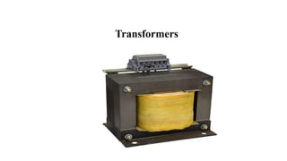
- 4. Transformer
- 5. Constructional details Main Components of a Transformer are, Magnetic core Primary & Secondary windings Insulation of windings Conservator tank & Explosion vent Bushings Buchholz relay Breather Cooling arrangements
- 6. Magnetic Core • Magnetic circuit consists of an iron core. • Core is made up of stacks of thin laminations (0.35mm thickness) of Cold Rolled Grain Oriented (CRGO) silicon steel. • These laminations are lightly insulated with varnish. • Two types of magnetic circuit are core type and shell type.
- 8. Core type construction • In the core type, the windings are wound around two legs of a rectangular magnetic core. • Windings surround the core & it has only one magnetic path.
- 9. Shell type construction • In shell type, the windings are wound around the center leg of a three-legged core • Core surrounds the windings.
- 10. Windings • A transformer has two windings namely primary and secondary. • These windings consist of a series of turns called coils, wound around the core. • Transformer windings are made of solid or stranded copper or aluminium strip conductors.
- 11. Conservator and Explosion Vent • Conservator is used to provide adequate space for the expansion of oil when transformer is loaded or when ambient temperature changes. • Explosion Vent is used to discharge excess pressure developed inside the transformer during loading, to the atmosphere.
- 12. Breather • It sucks the moisture from the air which is taken by transformer so that dry air is taken by transformer.
- 13. Bushings • Transformers are connected to high voltage lines. • Extreme care should be taken to prevent the conductors touching the transformer tank. • So the connections in and out of the transformer are made by the use of bushings. • Bushings are normally porcelain insulators.
- 14. Buchholz Relay • It is a safety device connected between main tank and conservator tank. • In case of slow developing faults, it sounds an alarm to alert the operator. • If serious fault occur in the transformer, it disconnects the transformer to protect it.
- 15. Methods of Cooling of Transformers • Air natural • Air Blast • Oil natural • Oil blast • Forced circulation of oil • Oil and water cooled • Forced oil and water cooled
- 16. Losses in a Transformer • The power losses in a transformer are of two types, namely; Core or Iron losses Copper losses
- 17. Core or Iron losses (Pi) • This loss consists of hysteresis and eddy current loss and occur in the transformer core due to the alternating flux. • These losses can be determined by open-circuit test. Hysteresis loss, Ph = Kh Bmax 1.6 f v watts Eddy current loss, Pe = Ke Bmax 2 f2 t2v watts • Both the above losses depend on Bm and frequency which are constant. • Hence, core or iron losses are practically the same at all loads.
- 18. Copper losses (PC) • These losses occur in both the primary and secondary windings due to their ohmic resistance. • These losses can be determined by short-circuit test. 𝑃𝐶 = 𝐼1 2 𝑅1 + 𝐼2 2 𝑅2 = 𝐼1 2 𝑅01 = 𝐼2 2 𝑅02 • Copper losses vary as the square of load current. • Copper losses account for about 90% of the total losses.
- 19. Summary Core loss It is the Constant loss Does not change even as the load current changes Proportional to supply voltage and frequency Copper loss or I2R loss It is a variable loss Also called as I2R loss Proportional to square of the load current Occurs in the winding resistances It is dissipated as heat
- 21. • When transferring resistance or reactance from primary to secondary, multiply it by K2. • When transferring resistance or reactance from secondary to primary, divide it by K2. Shifting Impedances
- 22. Simplified Equivalent Circuit of a Transformer
- 23. Equivalent Circuit of a Transformer
- 24. Equivalent Circuit Referred to Primary Side
- 25. Equivalent Circuit Referred to Primary Side
- 26. Equivalent Circuit Referred to Secondary Side
- 27. Equivalent Circuit Referred to Secondary Side
- 28. Testing of Transformers • The circuit constants, efficiency and voltage regulation of a transformer can be determined by two simple tests. (i) Open-circuit test (ii) Short-circuit lest
- 29. Open Circuit Test This test is conducted to determine R0 & X0 Rated voltage is applied on LV side & HV side is kept open. At no load, current taken by the transformer is 3-5% of full load current. So I2R loss is negligible. Therefore power consumed by the transformer on no load is considered as core loss.
- 30. Open Circuit Test Data observed from the test Supply voltage = V0 volts No load current = I0 amps Iron losses = W0 watts W0 = V0I0 CosФ0 CosФ0 = W0/(V0I0) IW = I0 CosФ0 Im = I0 SinФ0 R0 = V1/IW X0 = V1/Im
- 31. Short Circuit Test This test is conducted to determine R02 & X02 LV side of the Tfr is short circuited & the test is conducted on HV side. A low voltage is applied on the HV side to circulate the rated current on both the windings. Power drawn during this test is considered as copper loss.
- 32. Short Circuit Test Data observed from the test Applied voltage = VSC volts Short circuit current = ISC amps Copper losses = WSC watts WSC = ISC 2R02 R02= WSC/ISC 2 Z02=VSC/ISC X02=[Z02 2-R02 2]1/2
- 33. Efficiency • F.L. Iron loss = Pi ...from open-circuit test • F.L. Cu loss = PC ...from short-circuit test • Total losses = Pi + PC • Full-load efficiency of the transformer at any p.f. F. L. efficiency, ηfl = Full load VA × P. F Full load VA × P. F + Pi + PC
- 34. Efficiency • At any load (X times full-load), the total losses will be 𝑃𝑇 = 𝑃𝑖 + 𝑋2 𝑃𝐶 𝐸𝑓𝑓𝑖𝑐𝑖𝑒𝑛𝑐𝑦 𝑎𝑡 𝑋 𝑙𝑜𝑎𝑑, 𝜂𝑋 = (𝑋 × 𝐹𝑢𝑙𝑙 𝑙𝑜𝑎𝑑 𝑉𝐴 × 𝑃. 𝐹) 𝑋 × 𝐹𝑢𝑙𝑙 𝑙𝑜𝑎𝑑 𝑉𝐴 × 𝑃. 𝐹 + 𝑃𝑖 + 𝑋2𝑃𝐶 • Note that iron loss remains the same at all loads.
- 35. Condition for Maximum Efficiency 𝑂𝑢𝑡𝑝𝑢𝑡 𝑃𝑜𝑤𝑒𝑟 = 𝑉2𝐼2 𝑐𝑜𝑠 𝛷2 If R02 is the total resistance of the transformer referred to secondary, then, 𝑇𝑜𝑡𝑎𝑙 𝐶𝑜𝑝𝑝𝑒𝑟 𝑙𝑜𝑠𝑠, 𝑃𝐶 = 𝐼2 2 . 𝑅02 𝑇𝑜𝑡𝑎𝑙 𝑙𝑜𝑠𝑠𝑒𝑠 = 𝑃𝑖 + 𝑃𝐶 𝐸𝑓𝑓𝑖𝑐𝑖𝑒𝑛𝑐𝑦, 𝜂 = 𝑉2𝐼2 𝑐𝑜𝑠 𝛷2 𝑉2𝐼2 𝑐𝑜𝑠 𝛷2 + 𝑃𝑖 + 𝐼2 2 . 𝑅02 𝐸𝑓𝑓𝑖𝑐𝑖𝑒𝑛𝑐𝑦, 𝜂 = 𝑉2 𝑐𝑜𝑠 𝛷2 𝑉2 𝑐𝑜𝑠 𝛷2 + 𝑃𝑖 𝐼2 + 𝐼2 . 𝑅02
- 36. Condition for Maximum Efficiency 𝑑 𝑑𝐼2 𝑑𝑒𝑛𝑜𝑚𝑖𝑛𝑎𝑡𝑜𝑟 = 0 𝑑 𝑑𝐼2 V2 cos Φ2 + Pi I2 + I2 . R02 = 0 0 − 𝑃𝑖 𝐼2 2 + R02 = 0 𝑃𝑖 = 𝐼2 2 R02 • i.e, Iron loss = Copper loss
- 37. Condition for Maximum Efficiency • Hence efficiency of a transformer will be maximum when copper losses are equal to iron losses. • From above equation, the load current I2 corresponding to maximum efficiency is given by, 𝐼2 = 𝑃𝑖 R02
- 38. Output kVA Corresponding to Maximum Efficiency • PC = Copper losses at full-load kVA • Pi = Iron losses • X = Fraction of full-load kVA at which efficiency is maximum • Total Cu losses = X2 PC • For maximum efficiency, Pi = X2 PC ∴ X = Pi PC
- 39. Output kVA Corresponding to Maximum Efficiency Output kVA corresponding to max. efficiency = 𝑋 × Full load kVA Output kVA corresponding to max. efficiency = Full load kVA × Pi PC • It may be noted that the value of kVA, at which the efficiency is maximum, is independent of p.f. of the load.
- 40. Voltage Regulation • Change in secondary terminal voltage, when full load at a given power factor and at rated voltage is thrown off, is expressed as a percentage of rated terminal voltage. • The change in secondary terminal voltage from no load to full load expressed as a percentage of full load voltage. % 𝑽𝒐𝒍𝒕𝒂𝒈𝒆 𝑹𝒆𝒈𝒖𝒍𝒂𝒕𝒊𝒐𝒏 = 𝑽𝟐 𝑵.𝑳 − 𝑽𝟐 𝑭.𝑳 𝑽𝟐 𝑭.𝑳 × 𝟏𝟎𝟎%
- 41. Voltage Regulation at Different Power factors • Voltage regulation for lagging p.f at load X, % 𝒗𝒐𝒍𝒕𝒂𝒈𝒆 𝒓𝒆𝒈𝒖𝒍𝒂𝒕𝒊𝒐𝒏 = 𝑿. 𝑰𝟐 𝑹𝟎𝟐 𝐜𝐨𝐬 𝝓𝟐 + 𝑿𝟎𝟐 𝐬𝐢𝐧 𝝓𝟐 𝑽𝟐 × 𝟏𝟎𝟎% • Voltage regulation at leading p.f at load X, % 𝒗𝒐𝒍𝒕𝒂𝒈𝒆 𝒓𝒆𝒈𝒖𝒍𝒂𝒕𝒊𝒐𝒏 = 𝑿. 𝑰𝟐 𝑹𝟎𝟐 𝐜𝐨𝐬 𝝓𝟐 − 𝑿𝟎𝟐 𝐬𝐢𝐧 𝝓𝟐 𝑽𝟐 × 𝟏𝟎𝟎% • Voltage regulation at Unity p.f at load X, % 𝒗𝒐𝒍𝒕𝒂𝒈𝒆 𝒓𝒆𝒈𝒖𝒍𝒂𝒕𝒊𝒐𝒏 = 𝑿. 𝑰𝟐. 𝑹𝟎𝟐 𝑽𝟐 × 𝟏𝟎𝟎%
- 42. In a 25 kVA, 2000 V / 200 V transformer, the constant and variable losses are 350 W and 400 W respectively. Calculate the efficiency on unity power factor at full load and half the full load.
- 43. Calculate the efficiency at half and full load of a 100 kVA transformer for unity and 0.8 p.f. The copper loss is 1000 W at full load and iron loss is 1000 W.
- 44. Obtain the equivalent circuit of a 200 / 400 V, 50 Hz, 1 phase transformer from the following test data: O.C. test: 200 V, 0.7 A, 70 W – on L.V side. S.C. test: 15 V, 10 A, 85 W – on H.V side. Calculate the secondary voltage when delivering 5 kW at 0.8 p.f lagging, the primary voltage being 200 V.
- 45. From OC Test P0 = V0I0 cos ϕ0 cos ϕ0 = P0 V0I0 = 70 200 × 0.7 cos ϕ0 = 0.5 sin ϕ0 = 0.866 Iw = I0 cos ϕ0 = 0.7 × 0.5 = 0.35𝐴 Im = I0 sin ϕ0 = 0.7 × 0.866 = 0.606𝐴 R0 = V0 Iw = 70 0.35 = 200 Ω X0 = V0 Im = 70 0.606 = 115.5 Ω From SC Test Psc = Isc 2 R02 R02 = Psc Isc 2 = 85 102 = 0.85 Ω Z02 = Vsc Isc = 15 10 = 1.5 Ω X02 = Z02 2 − R02 2 X02 = 1.52 − 0.852 X02 = 1.235 Ω
- 46. Equivalent Circuit Referred to Primary Side 𝐾 = 400 200 = 2 R01 = 0.85 22 = 0.212 Ω X01 = 1.235 22 = 0.308 Ω
- 47. Equivalent Circuit Referred to Secondary Side 𝐾 = 400 200 = 2 𝑅0 ′ = 200 × 22 = 800 Ω 𝑋0 ′ = 115.5 × 22 = 462 Ω
- 48. • Load kVA corresponding to 5 kW is, = 5000 0.8 = 6250 𝑉𝐴 • Load current I2 while delivering 6250 VA is, = 6250 400 = 15.625 𝐴 • Total voltage drop in secondary when it carries 15.625 A is, = 𝐼2 𝑅02 𝑐𝑜𝑠 𝜙2 + 𝑋02 𝑠𝑖𝑛 𝜙2 = 15.625 0.85 × 0.8 + 1.235 × 0.6 = 22.20 𝑉 • Hence the secondary voltage is, 𝑉2 = 400 − 22.2 = 377.8 𝑉
- 49. All Day Efficiency • The ordinary or commercial efficiency of a transformer is defined as the ratio of output power to the input power i.e., Commercial efficiency = Output power Input power Primaries of distribution transformers are energized all the 24 hours in a day but the secondary windings supply little or no load during the major portion of the day.
- 50. All Day Efficiency • Constant loss occurs during the whole day but copper loss occurs only when the transformer is loaded. • The performance of such transformers is judged on the basis of energy consumption during the whole day (i.e., 24 hours). • This is known as all-day or energy efficiency.
- 51. All Day Efficiency • The ratio of output in kWh to the input in kWh of a transformer over a 24-hour period is known as all-day efficiency i.e., 𝜂𝑎𝑙𝑙−𝑑𝑎𝑦 = 𝑘𝑊ℎ 𝑜𝑢𝑡𝑝𝑢𝑡 𝑖𝑛 24 ℎ𝑜𝑢𝑟𝑠 𝑘𝑊ℎ 𝑖𝑛𝑝𝑢𝑡 𝑖𝑛 24 ℎ𝑜𝑢𝑟𝑠 • In the design of such transformers, efforts should be made to reduce the iron losses which continuously occur during the whole day.
- 52. All Day Efficiency • A 40kVA distribution transformer has iron loss of 500 W and full load copper loss of 500 W. the transformer is supplying a lighting load. The load cycle is as under: Full load for 4 hours, half load for 8 hours and no load for 12 hours. Calculate the all day efficiency.
- 53. All Day Efficiency • A transformer has its maximum efficiency of 0.98 at 15 kVA at UPF. During the day it is loaded as follows: Duration Load Power Factor 12 hours 2 kW at 0.5 p.f 6 hours 12 kW at 0.8 p.f 4 hours 18 kW at 0.9 p.f 2 hours No load • Find the “All Day Efficiency”.
- 54. Sumpner’s Test
- 55. Polarity Test • Similar polarity ends of two windings are those ends that acquire positive and negative polarity of emf induced in them simultaneously.
- 56. Auto Transformer • An autotransformer has a single winding on an iron core and a part of winding is common to both the primary and secondary circuits.
- 57. Auto Transformer • Primary and secondary windings are connected electrically as well as magnetically. • Therefore, power from the primary is transferred to the secondary conductively as well as inductively (transformer action). • The voltage transformation ratio K of an ideal autotransformer is, 𝐸1 𝐸2 = 𝑁1 𝑁2 = 𝑉1 𝑉2 = 𝐼2 𝐼1 = 𝐾
- 58. Advantages of Autotransformers • An autotransformer requires less Cu than a two -winding transformer of similar rating. • Autotransformer operates at a higher efficiency than a two-winding transformer of similar rating. • An autotransformer has better voltage regulation than a two-winding transformer of the same rating. • An autotransformer has smaller size than a two-winding transformer of the same rating.
- 59. Advantages of Autotransformers • An autotransformer requires smaller exciting current than a two- winding transformer of the same rating. • These advantages decrease as the ratio of transformation increases. So an autotransformer has advantages only for low values of transformation ratio.
- 60. Disadvantages of Autotransformers • There is a direct connection between the primary and secondary. Therefore, the output is no longer isolated from the input. • It is not safe for stepping down a high voltage to a low voltage. • The short - circuit current is much larger than for the two-winding transformer of the same rating. • This reduces the effective resistance and reactance.
- 61. Applications of Autotransformers • Autotransformers are used to compensate for voltage drops in transmission and distribution lines. When used for this purpose, they are known as booster transformers. • Autotransformers are used for reducing the voltage supplied to a.c. motors during the starting period. • Autotransformers are used for continuous variable supply.
- 62. Three Phase Transformers • Large scale generation of electric power is usually 3 phase at 13.2 kV or higher. • But transmission voltage is 110 kV, 132 kV and 400 kV. • Generated voltage needs to be increased. • Hence 3 phase transformers are used. • 3 single phase transformers can be used to construct a 3 phase transformer. • But it occupies more space and 15% more costlier than using a single unit.
- 64. Three Phase Transformer Connections • Star / Star (Y – Y) • Delta / Delta (Δ – Δ) • Star / Delta(Y – Δ) • Delta / Star (V – Y)