SlideShare una empresa de Scribd logo
1 de 17
Sharavathi Receiving Station
Hootagalli Substation , Mysuru
NIE INSTITUTE OF TECHNOLOGY
To
Assistant Executive Engineer
KPTCL,SRS Hootagalli Substation, Mysuru
BY
H . C . Naveen . Kumar (4NN14EE013)
D . V . Manjunath (4NN14EE012)
CONTENT
• Introduction
• About Hootagalli SRS Substation
• Single Line Diagram of SRS
• List of component in Substation
• Description of the yard
• Control Room
• Battery Room
INTRODUCTIOIN
Sharavati Hydroelectric project
Originating at a height of 730 m near Ambuthirtha, in Shimoga district,
the Sharavathi river flows in a north-west direction.
 In its long, 132-km journey, it is joined by several tributaries after a stretch of 80 km along its course,
the river drops down a steep mountain face of 293m – spectacle known as the Jog Falls.
The Sharavati Hydroelectric project was started to tap the electricity generating potential of the river,
three power generating stations in this project
 The Sharavati Generating Station with 10 Units and an installed capacity of 1035 MW
 The Linganamakki Dam Powerhouse with 2 units and an installed capacity of 55 MW
The Gerusoppa Dam Project with 4 units totalling to 240 MW.
The KPCL blueprint identifies Sharavathi as its “Master Station” – a headpoint that will control all
peripheral stations through a nodal monitoring system. The prime objective here is to optimize power
generation through a systematic integration of several reservoirs and water conductor systems.
About Hootagalli SRS Station
A substation is an assembly of apparatus, which transform’s the characteristics of electrical
energy from one form to another , from one voltage level to another level. Hence a substation is
an intermediate link between the generating station and the load units.
There are total three, 220KV incoming feeders in SRS receiving station
 Kadakola Line
 Basthipura no 1 line
 Basthipura no 2 line
The incoming feeders are connected to bus-bar through lightning arresters , line isolator, circuit
breakers , current-transformers etc. .The bus-bars are to have an arrangement of auxiliary bus.
The incoming 220KV supply is stepped down to 66KV using 100MVA transformer. The 220KV
SRS station consist of 3 nos. of 100MVA transformer, with there voltage ratio respectively are
220/66/11kv.
 The incoming 220kv line also forwarded to other region, there is one 220KV outgoing line to
Vijaymangala.
SINGLE LINE DIAGRAM OF 220 KV SRS HOOTAGALLY,MYSORE
Components in the Power station
 Power transformer: 100MVA &12.5MVA
 Circuit breakers:220KV,110KV,66KV,11KV
 66KV capacitor banks
 Potential transformer:220KV bus PT,66KV bus PT
 Current transformer:220KV,66KV,11KV
 Capacitor voltage transformers: 220KV ,66KV
 Isolator: 220KV,66KV,11KV
 Lightning arrestor:220Kv,66KV
 Auxiliary transformer
 Battery and battery charger
 Relays
 Centralized air compressor
Power Transformer
A static electrical machine used for transforming power from one circuit to
another circuit without changing frequency is termed as power transformer.
 The transformers are generally used to step down or step up the voltage level
of a system for transmission and generation purpose.
Description of the yard
Circuit Breaker
Operation
 A circuit breaker can make or breaker circuit either manually or automatically under all condition as no load , full
load and short circuit condition.
 Circuit breaker essentially consists of fixed and moving contacts. These contacts can be opened manually or by
remote control whenever desired. When a fault occurs on any part of the system, the trip coils of breaker get
energized and the moving contacts are pulled apart by some mechanism, thus opening the circuit.
 When contacts of a circuit breaker are separated, an arc is struck; the current is thus able to continue. The
production of arcs are not only delays the current interruption, but is also generates the heat. Therefore, the main
problem is to distinguish the arc within the shortest possible time so that it may not reach a dangerous value
 SF6 circuit breaker: Current interruption in a high-voltage circuit breaker is
obtained by separating two contacts in a medium, such as sulfur hexafluoride
(SF6), having excellent dielectric and arc-quenching properties. After contact
separation, current is carried through an arc and is interrupted when this arc
is cooled by a gas blast of sufficient intensity.
Types of Circuit breaker
1.Oil Circuit Breaker
2.Air -Blast Circuit Breaker
3.Sulphur Hexafluoride Circuit Breaker (Sf6)
CAPACITOR BANK
Capacitor bank accomplishes following operations
1. Supply reactive power
2. Increases terminal voltage
3. Improve power factor
 The load on the power system is varying being high during morning and evening
which increases the magnetization current. This result in the decreased power factor.
The low power factor is mainly due to the fact most of the power loads are inductive
and therefore take lagging currents. The low power factor is highly undesirable as it
causes rise in current, resulting in additional losses.
In order to improve the power factor come device taking leading power should be
connected in parallel with the load. One of the such device can be capacitor bank. The
capacitor draws a leading current and partly or completely neutralize the lagging reactive
component of load current.
CURRENT TRANSFORMER
Current transformer is used for measurement of
the altering current by taking samples of high
current of the system.
These reduced samples are in accurate
proportions with actual high current of system.
These are used for installation and maintenance
of current relay in substation for protection
purpose which are normally have low-current
for their operation
POTENTIAL TRANSFORMER
Potential transformer is quite similar to the current transformer, but it is
used for taking samples of high voltages of a system for providing low-
voltage to the relays of protection system and also to the low-rating meter
for voltage measurement.
From this low-voltage measurement, actual system’s high voltage can be
calculated without measuring high voltage directly to avoid the cost of the
measuring system.
BUS BAR
When numbers of generators or feeders operating at the
same voltage have to be directly connected electrically,
bus bar is used as the common electrical component. Bus
bars are made up of copper rods operate at constant
voltage.
The following are the important bus bars arrangements
used at substations:
1. Single bus bar system.
2.Duplicate bus bar system.
.
 In substations, it is often desired to disconnect a part of the system for general maintenance
and repairs. Isolator operates under no load condition.
 While opening a circuit, the circuit breaker is opened first then isolator while closing a
circuit the isolator is closed first, then circuit breakers. Isolators are necessary on supply
side of circuit breakers, in order to ensure isolation of the circuit breaker from live parts for
the purpose of maintenance.
Lightening Arrester
The substation equipment's such as conductor,
transformer etc., are always erected outdoor.
Whenever light surges occur then, a high-voltage
pass through these electrical components causing
damage to them.
Therefore to avoid this difficulty, lightening
arrester are placed to pass entire lightening
surge to earth.
Relay
Relays are used for disconnected the circuit by manual or automatic
operation.
Relay consists of coil which is excited or energized and such that the
making the contacts of relay closed ,activates the relay to break or make
the connection.
There are different types of relay such as current relay, microprocessor
relay, mho relay, Buchholz relay etc., . The SR substation uses Buchholz
relay and many other types of relays.
Isolator
 Isolator is a manually operated mechanical switch that isolates a part of a
circuit of substation meant for repair from a healthy section in order to
avoid occurrence of more fault. Hence it is also called as disconnecter.
There are different types of isolators such as single-break isolator, double-
break isolator, bus isolator, line isolator etc.
Insulator
The substance which does not allow free movement of electron is
called as insulator. There are different types of insulators such as
suspension type, strain type, pin type so on.
 Insulator are used or insulation purpose while erecting electric
poles with conductors to avoid short circuit and for other purpose.
 It is used to trap the high frequency communication
signals sent on the line from the remote substation
and diverting them to the telecom/tele-protection
panel in the substation control room. Line trap also is
known as Wave trap.
Wave Trap
 Bus voltages and frequencies, line loading, transformer loading, power
factor, temperature, etc. are the basic variables related with substation
control and instrumentation.
 The various supervision, control and protection function are preformed
in substation control room. The relays, protection and control panels
are installed in the controlled room. These panels along with PC aids in
automatic operation of various circuit breakers tap changers, auto-
recloses, sectionalizing switches and other devices during faults and
abnormal conditions.
Control room
 When the oil expands or contacts by the change in the temperature, the oil
level goes either up or down in main tank. A conservator is used to
maintain the oil level up to predetermined value in the transformer main
tank by placing it above the level of the top of the tank.
 Breather is connected to conservator tank for the purpose of extracting
moisture as it spoils the insulating properties of the oil. During the
contraction and expansion of oil air is drawn in or out through breather
silica gel crystals impregnated with cobalt chloride. Silica gel is checked
regularly and dried and replaced when necessary.
Conservator and Breather
BATTERY ROOM
There is a battery room which has 110 batteries of 2 volt each for 220KV section. Therefore D.C. power available is
for functioning of the control panels. A battery charger to charge the battery.
1.Various parts of lead acid batteries
2.Plates
3.Separators
4.Electrolyte
5.Container
6.Terminal port
7.Vent plugs
CHARGING OF BATTERIES
Initial charging
It is the first charging given to batteries by which the positive plates are converted to “lead peroxide", where
as the –ve plates will converted to spongy lead. Also in a fully charged battery the electrolyte specific gravity
will be at its highest venue or 1.2 and its terminal voltage will be 24 volts.
DISCHARGING
When a fully charged battery delivers its energy out by meeting a load the lead peroxide of the +ve plates slowly gets
converted to lead sulphate and the spongy lead of the –ve plates also gets converted into lead sulphate during this time the
specific gravity of the electrolyte also decreases the value around 1.00 and the terminal voltage also decreases from its initial
to a lower value which may be around 1.85 or 1.8.

Más contenido relacionado

La actualidad más candente

presentation on 400kv gss heerapura @mnit
presentation on 400kv gss heerapura @mnitpresentation on 400kv gss heerapura @mnit
presentation on 400kv gss heerapura @mnitSuresh Choudhary
 
substation internship report
substation internship report substation internship report
substation internship report Arun Thapa
 
Applications of power electronics in HVDC
Applications of  power electronics in HVDCApplications of  power electronics in HVDC
Applications of power electronics in HVDCKabilesh K
 
Bundle conductors in transmission line
Bundle conductors in transmission line Bundle conductors in transmission line
Bundle conductors in transmission line chandan kumar
 
APFC project presentation
APFC project presentationAPFC project presentation
APFC project presentationkartickmp613
 
POWER SYSTEM PROTECTION
POWER SYSTEM PROTECTION POWER SYSTEM PROTECTION
POWER SYSTEM PROTECTION moiz89
 
Ppt of ehv ac transmission
Ppt of ehv ac transmissionPpt of ehv ac transmission
Ppt of ehv ac transmissionSumit Kumar
 
220 kv Sub-station Summer Training ppt
220 kv Sub-station Summer Training ppt220 kv Sub-station Summer Training ppt
220 kv Sub-station Summer Training pptShubham Patel
 
Various Bus-Bar Arrangements.
Various Bus-Bar Arrangements.Various Bus-Bar Arrangements.
Various Bus-Bar Arrangements.SaiSampath16
 
protection of transmission lines[distance relay protection scheme]
protection of transmission lines[distance relay protection scheme]protection of transmission lines[distance relay protection scheme]
protection of transmission lines[distance relay protection scheme]moiz89
 
Protection schemes and zones
Protection schemes and zonesProtection schemes and zones
Protection schemes and zonesSlides Hub
 
protection scheme of a grid substation prsentation
protection scheme of a grid substation prsentationprotection scheme of a grid substation prsentation
protection scheme of a grid substation prsentationabu jubayer
 
FLYBACK CONVERTER PPT
FLYBACK CONVERTER PPTFLYBACK CONVERTER PPT
FLYBACK CONVERTER PPTAjmal Khan
 
automatic meter reading
automatic meter readingautomatic meter reading
automatic meter readingmsubashece001
 

La actualidad más candente (20)

presentation on 400kv gss heerapura @mnit
presentation on 400kv gss heerapura @mnitpresentation on 400kv gss heerapura @mnit
presentation on 400kv gss heerapura @mnit
 
substation internship report
substation internship report substation internship report
substation internship report
 
Applications of power electronics in HVDC
Applications of  power electronics in HVDCApplications of  power electronics in HVDC
Applications of power electronics in HVDC
 
Switchyard
SwitchyardSwitchyard
Switchyard
 
132kV GSS ppt
132kV GSS ppt132kV GSS ppt
132kV GSS ppt
 
Bundle conductors in transmission line
Bundle conductors in transmission line Bundle conductors in transmission line
Bundle conductors in transmission line
 
APFC project presentation
APFC project presentationAPFC project presentation
APFC project presentation
 
POWER SYSTEM PROTECTION
POWER SYSTEM PROTECTION POWER SYSTEM PROTECTION
POWER SYSTEM PROTECTION
 
Ppt of ehv ac transmission
Ppt of ehv ac transmissionPpt of ehv ac transmission
Ppt of ehv ac transmission
 
220 kv Sub-station Summer Training ppt
220 kv Sub-station Summer Training ppt220 kv Sub-station Summer Training ppt
220 kv Sub-station Summer Training ppt
 
Various Bus-Bar Arrangements.
Various Bus-Bar Arrangements.Various Bus-Bar Arrangements.
Various Bus-Bar Arrangements.
 
132 kv
132 kv132 kv
132 kv
 
Insulators
Insulators Insulators
Insulators
 
protection of transmission lines[distance relay protection scheme]
protection of transmission lines[distance relay protection scheme]protection of transmission lines[distance relay protection scheme]
protection of transmission lines[distance relay protection scheme]
 
Chapter 01- High Voltage Engineering Introduction
Chapter 01- High Voltage Engineering IntroductionChapter 01- High Voltage Engineering Introduction
Chapter 01- High Voltage Engineering Introduction
 
Protection schemes and zones
Protection schemes and zonesProtection schemes and zones
Protection schemes and zones
 
Phasor Measurement Unit (PMU)
 Phasor Measurement Unit (PMU) Phasor Measurement Unit (PMU)
Phasor Measurement Unit (PMU)
 
protection scheme of a grid substation prsentation
protection scheme of a grid substation prsentationprotection scheme of a grid substation prsentation
protection scheme of a grid substation prsentation
 
FLYBACK CONVERTER PPT
FLYBACK CONVERTER PPTFLYBACK CONVERTER PPT
FLYBACK CONVERTER PPT
 
automatic meter reading
automatic meter readingautomatic meter reading
automatic meter reading
 

Similar a Sharavati receiving station

Rajasthan Rajya Vidyut Prasaran Nigam.pptx
Rajasthan Rajya Vidyut Prasaran Nigam.pptxRajasthan Rajya Vidyut Prasaran Nigam.pptx
Rajasthan Rajya Vidyut Prasaran Nigam.pptxsohaib268827
 
Report on 220kv substation at Jassure
Report on 220kv substation at JassureReport on 220kv substation at Jassure
Report on 220kv substation at JassureShuvam Pathania
 
sub subsation seminar ppt.pptx
sub subsation seminar ppt.pptxsub subsation seminar ppt.pptx
sub subsation seminar ppt.pptxfallinhay
 
Amanppt 140826070457-phpapp02
Amanppt 140826070457-phpapp02Amanppt 140826070457-phpapp02
Amanppt 140826070457-phpapp02Md Hasan
 
132KV SUBSTATION UPPTCL
132KV SUBSTATION UPPTCL132KV SUBSTATION UPPTCL
132KV SUBSTATION UPPTCLAman Rajput
 
UPPCL,33/11KV H.A.L SUBSTATION,INDIRANAGAR(LUCKNOW)
UPPCL,33/11KV H.A.L SUBSTATION,INDIRANAGAR(LUCKNOW)UPPCL,33/11KV H.A.L SUBSTATION,INDIRANAGAR(LUCKNOW)
UPPCL,33/11KV H.A.L SUBSTATION,INDIRANAGAR(LUCKNOW)Sogendra Rajput
 
WBSETCL Subhash Gram 220KV Substation Training Report
WBSETCL Subhash Gram 220KV Substation Training ReportWBSETCL Subhash Gram 220KV Substation Training Report
WBSETCL Subhash Gram 220KV Substation Training ReportArijit Basu
 
Presentation 2014
Presentation 2014Presentation 2014
Presentation 2014pinki199319
 
Visit to 400 kV substation, Hadala
Visit to 400 kV substation, HadalaVisit to 400 kV substation, Hadala
Visit to 400 kV substation, HadalaNandan Desai
 
Presentation on 132/33KV BSPTCL(Bodhgaya Substation)
Presentation on 132/33KV BSPTCL(Bodhgaya Substation)Presentation on 132/33KV BSPTCL(Bodhgaya Substation)
Presentation on 132/33KV BSPTCL(Bodhgaya Substation)Rahul Prajapati
 
Switchyard design overview
Switchyard design overviewSwitchyard design overview
Switchyard design overviewMilind Punj
 
Uttar pradesh power corporation limited
Uttar pradesh power corporation limitedUttar pradesh power corporation limited
Uttar pradesh power corporation limitedVSRAGHU
 
Report On Industrial Tour At Khulshi Grid Sub-Station
Report On Industrial Tour At Khulshi Grid Sub-StationReport On Industrial Tour At Khulshi Grid Sub-Station
Report On Industrial Tour At Khulshi Grid Sub-StationEkram Bin Mamun
 
Load Distribution
Load DistributionLoad Distribution
Load DistributionArpit Gupta
 
pptravi-191011011024 (1).pdf
pptravi-191011011024 (1).pdfpptravi-191011011024 (1).pdf
pptravi-191011011024 (1).pdfHariomgupta90
 
PPT ON 33/11KV SUBSTATION
PPT ON 33/11KV SUBSTATIONPPT ON 33/11KV SUBSTATION
PPT ON 33/11KV SUBSTATIONRavi Phadtare
 
Design of substation
Design of substationDesign of substation
Design of substationSayanSarkar55
 

Similar a Sharavati receiving station (20)

Rajasthan Rajya Vidyut Prasaran Nigam.pptx
Rajasthan Rajya Vidyut Prasaran Nigam.pptxRajasthan Rajya Vidyut Prasaran Nigam.pptx
Rajasthan Rajya Vidyut Prasaran Nigam.pptx
 
Report on 220kv substation at Jassure
Report on 220kv substation at JassureReport on 220kv substation at Jassure
Report on 220kv substation at Jassure
 
sub subsation seminar ppt.pptx
sub subsation seminar ppt.pptxsub subsation seminar ppt.pptx
sub subsation seminar ppt.pptx
 
Amanppt 140826070457-phpapp02
Amanppt 140826070457-phpapp02Amanppt 140826070457-phpapp02
Amanppt 140826070457-phpapp02
 
132KV SUBSTATION UPPTCL
132KV SUBSTATION UPPTCL132KV SUBSTATION UPPTCL
132KV SUBSTATION UPPTCL
 
Ashwani kumar
Ashwani kumarAshwani kumar
Ashwani kumar
 
UPPCL,33/11KV H.A.L SUBSTATION,INDIRANAGAR(LUCKNOW)
UPPCL,33/11KV H.A.L SUBSTATION,INDIRANAGAR(LUCKNOW)UPPCL,33/11KV H.A.L SUBSTATION,INDIRANAGAR(LUCKNOW)
UPPCL,33/11KV H.A.L SUBSTATION,INDIRANAGAR(LUCKNOW)
 
WBSETCL Subhash Gram 220KV Substation Training Report
WBSETCL Subhash Gram 220KV Substation Training ReportWBSETCL Subhash Gram 220KV Substation Training Report
WBSETCL Subhash Gram 220KV Substation Training Report
 
Presentation 2014
Presentation 2014Presentation 2014
Presentation 2014
 
Visit to 400 kV substation, Hadala
Visit to 400 kV substation, HadalaVisit to 400 kV substation, Hadala
Visit to 400 kV substation, Hadala
 
Presentation on 132/33KV BSPTCL(Bodhgaya Substation)
Presentation on 132/33KV BSPTCL(Bodhgaya Substation)Presentation on 132/33KV BSPTCL(Bodhgaya Substation)
Presentation on 132/33KV BSPTCL(Bodhgaya Substation)
 
Switchyard design overview
Switchyard design overviewSwitchyard design overview
Switchyard design overview
 
Uttar pradesh power corporation limited
Uttar pradesh power corporation limitedUttar pradesh power corporation limited
Uttar pradesh power corporation limited
 
Report On Industrial Tour At Khulshi Grid Sub-Station
Report On Industrial Tour At Khulshi Grid Sub-StationReport On Industrial Tour At Khulshi Grid Sub-Station
Report On Industrial Tour At Khulshi Grid Sub-Station
 
Load Distribution
Load DistributionLoad Distribution
Load Distribution
 
pptravi-191011011024 (1).pdf
pptravi-191011011024 (1).pdfpptravi-191011011024 (1).pdf
pptravi-191011011024 (1).pdf
 
Gss ppt by kanhaiya
Gss ppt  by kanhaiyaGss ppt  by kanhaiya
Gss ppt by kanhaiya
 
PPT ON 33/11KV SUBSTATION
PPT ON 33/11KV SUBSTATIONPPT ON 33/11KV SUBSTATION
PPT ON 33/11KV SUBSTATION
 
Design of substation
Design of substationDesign of substation
Design of substation
 
Summer Training presentation on 132/33 KV sub-station Minto park, Allahabad
Summer Training presentation on 132/33 KV sub-station Minto park, AllahabadSummer Training presentation on 132/33 KV sub-station Minto park, Allahabad
Summer Training presentation on 132/33 KV sub-station Minto park, Allahabad
 

Último

Past, Present and Future of Generative AI
Past, Present and Future of Generative AIPast, Present and Future of Generative AI
Past, Present and Future of Generative AIabhishek36461
 
An experimental study in using natural admixture as an alternative for chemic...
An experimental study in using natural admixture as an alternative for chemic...An experimental study in using natural admixture as an alternative for chemic...
An experimental study in using natural admixture as an alternative for chemic...Chandu841456
 
US Department of Education FAFSA Week of Action
US Department of Education FAFSA Week of ActionUS Department of Education FAFSA Week of Action
US Department of Education FAFSA Week of ActionMebane Rash
 
Correctly Loading Incremental Data at Scale
Correctly Loading Incremental Data at ScaleCorrectly Loading Incremental Data at Scale
Correctly Loading Incremental Data at ScaleAlluxio, Inc.
 
welding defects observed during the welding
welding defects observed during the weldingwelding defects observed during the welding
welding defects observed during the weldingMuhammadUzairLiaqat
 
IVE Industry Focused Event - Defence Sector 2024
IVE Industry Focused Event - Defence Sector 2024IVE Industry Focused Event - Defence Sector 2024
IVE Industry Focused Event - Defence Sector 2024Mark Billinghurst
 
Research Methodology for Engineering pdf
Research Methodology for Engineering pdfResearch Methodology for Engineering pdf
Research Methodology for Engineering pdfCaalaaAbdulkerim
 
Energy Awareness training ppt for manufacturing process.pptx
Energy Awareness training ppt for manufacturing process.pptxEnergy Awareness training ppt for manufacturing process.pptx
Energy Awareness training ppt for manufacturing process.pptxsiddharthjain2303
 
Earthing details of Electrical Substation
Earthing details of Electrical SubstationEarthing details of Electrical Substation
Earthing details of Electrical Substationstephanwindworld
 
Risk Assessment For Installation of Drainage Pipes.pdf
Risk Assessment For Installation of Drainage Pipes.pdfRisk Assessment For Installation of Drainage Pipes.pdf
Risk Assessment For Installation of Drainage Pipes.pdfROCENODodongVILLACER
 
Call Girls Narol 7397865700 Independent Call Girls
Call Girls Narol 7397865700 Independent Call GirlsCall Girls Narol 7397865700 Independent Call Girls
Call Girls Narol 7397865700 Independent Call Girlsssuser7cb4ff
 
THE SENDAI FRAMEWORK FOR DISASTER RISK REDUCTION
THE SENDAI FRAMEWORK FOR DISASTER RISK REDUCTIONTHE SENDAI FRAMEWORK FOR DISASTER RISK REDUCTION
THE SENDAI FRAMEWORK FOR DISASTER RISK REDUCTIONjhunlian
 
National Level Hackathon Participation Certificate.pdf
National Level Hackathon Participation Certificate.pdfNational Level Hackathon Participation Certificate.pdf
National Level Hackathon Participation Certificate.pdfRajuKanojiya4
 
Steel Structures - Building technology.pptx
Steel Structures - Building technology.pptxSteel Structures - Building technology.pptx
Steel Structures - Building technology.pptxNikhil Raut
 
Unit7-DC_Motors nkkjnsdkfnfcdfknfdgfggfg
Unit7-DC_Motors nkkjnsdkfnfcdfknfdgfggfgUnit7-DC_Motors nkkjnsdkfnfcdfknfdgfggfg
Unit7-DC_Motors nkkjnsdkfnfcdfknfdgfggfgsaravananr517913
 
Indian Dairy Industry Present Status and.ppt
Indian Dairy Industry Present Status and.pptIndian Dairy Industry Present Status and.ppt
Indian Dairy Industry Present Status and.pptMadan Karki
 
Input Output Management in Operating System
Input Output Management in Operating SystemInput Output Management in Operating System
Input Output Management in Operating SystemRashmi Bhat
 
Virtual memory management in Operating System
Virtual memory management in Operating SystemVirtual memory management in Operating System
Virtual memory management in Operating SystemRashmi Bhat
 

Último (20)

Past, Present and Future of Generative AI
Past, Present and Future of Generative AIPast, Present and Future of Generative AI
Past, Present and Future of Generative AI
 
An experimental study in using natural admixture as an alternative for chemic...
An experimental study in using natural admixture as an alternative for chemic...An experimental study in using natural admixture as an alternative for chemic...
An experimental study in using natural admixture as an alternative for chemic...
 
US Department of Education FAFSA Week of Action
US Department of Education FAFSA Week of ActionUS Department of Education FAFSA Week of Action
US Department of Education FAFSA Week of Action
 
Correctly Loading Incremental Data at Scale
Correctly Loading Incremental Data at ScaleCorrectly Loading Incremental Data at Scale
Correctly Loading Incremental Data at Scale
 
welding defects observed during the welding
welding defects observed during the weldingwelding defects observed during the welding
welding defects observed during the welding
 
IVE Industry Focused Event - Defence Sector 2024
IVE Industry Focused Event - Defence Sector 2024IVE Industry Focused Event - Defence Sector 2024
IVE Industry Focused Event - Defence Sector 2024
 
Research Methodology for Engineering pdf
Research Methodology for Engineering pdfResearch Methodology for Engineering pdf
Research Methodology for Engineering pdf
 
Energy Awareness training ppt for manufacturing process.pptx
Energy Awareness training ppt for manufacturing process.pptxEnergy Awareness training ppt for manufacturing process.pptx
Energy Awareness training ppt for manufacturing process.pptx
 
Earthing details of Electrical Substation
Earthing details of Electrical SubstationEarthing details of Electrical Substation
Earthing details of Electrical Substation
 
Risk Assessment For Installation of Drainage Pipes.pdf
Risk Assessment For Installation of Drainage Pipes.pdfRisk Assessment For Installation of Drainage Pipes.pdf
Risk Assessment For Installation of Drainage Pipes.pdf
 
POWER SYSTEMS-1 Complete notes examples
POWER SYSTEMS-1 Complete notes  examplesPOWER SYSTEMS-1 Complete notes  examples
POWER SYSTEMS-1 Complete notes examples
 
Call Girls Narol 7397865700 Independent Call Girls
Call Girls Narol 7397865700 Independent Call GirlsCall Girls Narol 7397865700 Independent Call Girls
Call Girls Narol 7397865700 Independent Call Girls
 
THE SENDAI FRAMEWORK FOR DISASTER RISK REDUCTION
THE SENDAI FRAMEWORK FOR DISASTER RISK REDUCTIONTHE SENDAI FRAMEWORK FOR DISASTER RISK REDUCTION
THE SENDAI FRAMEWORK FOR DISASTER RISK REDUCTION
 
National Level Hackathon Participation Certificate.pdf
National Level Hackathon Participation Certificate.pdfNational Level Hackathon Participation Certificate.pdf
National Level Hackathon Participation Certificate.pdf
 
Steel Structures - Building technology.pptx
Steel Structures - Building technology.pptxSteel Structures - Building technology.pptx
Steel Structures - Building technology.pptx
 
Unit7-DC_Motors nkkjnsdkfnfcdfknfdgfggfg
Unit7-DC_Motors nkkjnsdkfnfcdfknfdgfggfgUnit7-DC_Motors nkkjnsdkfnfcdfknfdgfggfg
Unit7-DC_Motors nkkjnsdkfnfcdfknfdgfggfg
 
Indian Dairy Industry Present Status and.ppt
Indian Dairy Industry Present Status and.pptIndian Dairy Industry Present Status and.ppt
Indian Dairy Industry Present Status and.ppt
 
Input Output Management in Operating System
Input Output Management in Operating SystemInput Output Management in Operating System
Input Output Management in Operating System
 
🔝9953056974🔝!!-YOUNG call girls in Rajendra Nagar Escort rvice Shot 2000 nigh...
🔝9953056974🔝!!-YOUNG call girls in Rajendra Nagar Escort rvice Shot 2000 nigh...🔝9953056974🔝!!-YOUNG call girls in Rajendra Nagar Escort rvice Shot 2000 nigh...
🔝9953056974🔝!!-YOUNG call girls in Rajendra Nagar Escort rvice Shot 2000 nigh...
 
Virtual memory management in Operating System
Virtual memory management in Operating SystemVirtual memory management in Operating System
Virtual memory management in Operating System
 

Sharavati receiving station

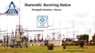
  • 1. Sharavathi Receiving Station Hootagalli Substation , Mysuru NIE INSTITUTE OF TECHNOLOGY To Assistant Executive Engineer KPTCL,SRS Hootagalli Substation, Mysuru BY H . C . Naveen . Kumar (4NN14EE013) D . V . Manjunath (4NN14EE012)
  • 2. CONTENT • Introduction • About Hootagalli SRS Substation • Single Line Diagram of SRS • List of component in Substation • Description of the yard • Control Room • Battery Room
  • 3. INTRODUCTIOIN Sharavati Hydroelectric project Originating at a height of 730 m near Ambuthirtha, in Shimoga district, the Sharavathi river flows in a north-west direction.  In its long, 132-km journey, it is joined by several tributaries after a stretch of 80 km along its course, the river drops down a steep mountain face of 293m – spectacle known as the Jog Falls. The Sharavati Hydroelectric project was started to tap the electricity generating potential of the river, three power generating stations in this project  The Sharavati Generating Station with 10 Units and an installed capacity of 1035 MW  The Linganamakki Dam Powerhouse with 2 units and an installed capacity of 55 MW The Gerusoppa Dam Project with 4 units totalling to 240 MW. The KPCL blueprint identifies Sharavathi as its “Master Station” – a headpoint that will control all peripheral stations through a nodal monitoring system. The prime objective here is to optimize power generation through a systematic integration of several reservoirs and water conductor systems.
  • 4. About Hootagalli SRS Station A substation is an assembly of apparatus, which transform’s the characteristics of electrical energy from one form to another , from one voltage level to another level. Hence a substation is an intermediate link between the generating station and the load units. There are total three, 220KV incoming feeders in SRS receiving station  Kadakola Line  Basthipura no 1 line  Basthipura no 2 line The incoming feeders are connected to bus-bar through lightning arresters , line isolator, circuit breakers , current-transformers etc. .The bus-bars are to have an arrangement of auxiliary bus. The incoming 220KV supply is stepped down to 66KV using 100MVA transformer. The 220KV SRS station consist of 3 nos. of 100MVA transformer, with there voltage ratio respectively are 220/66/11kv.  The incoming 220kv line also forwarded to other region, there is one 220KV outgoing line to Vijaymangala.
  • 5. SINGLE LINE DIAGRAM OF 220 KV SRS HOOTAGALLY,MYSORE
  • 6. Components in the Power station  Power transformer: 100MVA &12.5MVA  Circuit breakers:220KV,110KV,66KV,11KV  66KV capacitor banks  Potential transformer:220KV bus PT,66KV bus PT  Current transformer:220KV,66KV,11KV  Capacitor voltage transformers: 220KV ,66KV  Isolator: 220KV,66KV,11KV  Lightning arrestor:220Kv,66KV  Auxiliary transformer  Battery and battery charger  Relays  Centralized air compressor
  • 7. Power Transformer A static electrical machine used for transforming power from one circuit to another circuit without changing frequency is termed as power transformer.  The transformers are generally used to step down or step up the voltage level of a system for transmission and generation purpose. Description of the yard
  • 8. Circuit Breaker Operation  A circuit breaker can make or breaker circuit either manually or automatically under all condition as no load , full load and short circuit condition.  Circuit breaker essentially consists of fixed and moving contacts. These contacts can be opened manually or by remote control whenever desired. When a fault occurs on any part of the system, the trip coils of breaker get energized and the moving contacts are pulled apart by some mechanism, thus opening the circuit.  When contacts of a circuit breaker are separated, an arc is struck; the current is thus able to continue. The production of arcs are not only delays the current interruption, but is also generates the heat. Therefore, the main problem is to distinguish the arc within the shortest possible time so that it may not reach a dangerous value  SF6 circuit breaker: Current interruption in a high-voltage circuit breaker is obtained by separating two contacts in a medium, such as sulfur hexafluoride (SF6), having excellent dielectric and arc-quenching properties. After contact separation, current is carried through an arc and is interrupted when this arc is cooled by a gas blast of sufficient intensity. Types of Circuit breaker 1.Oil Circuit Breaker 2.Air -Blast Circuit Breaker 3.Sulphur Hexafluoride Circuit Breaker (Sf6)
  • 9. CAPACITOR BANK Capacitor bank accomplishes following operations 1. Supply reactive power 2. Increases terminal voltage 3. Improve power factor  The load on the power system is varying being high during morning and evening which increases the magnetization current. This result in the decreased power factor. The low power factor is mainly due to the fact most of the power loads are inductive and therefore take lagging currents. The low power factor is highly undesirable as it causes rise in current, resulting in additional losses. In order to improve the power factor come device taking leading power should be connected in parallel with the load. One of the such device can be capacitor bank. The capacitor draws a leading current and partly or completely neutralize the lagging reactive component of load current.
  • 10. CURRENT TRANSFORMER Current transformer is used for measurement of the altering current by taking samples of high current of the system. These reduced samples are in accurate proportions with actual high current of system. These are used for installation and maintenance of current relay in substation for protection purpose which are normally have low-current for their operation
  • 11. POTENTIAL TRANSFORMER Potential transformer is quite similar to the current transformer, but it is used for taking samples of high voltages of a system for providing low- voltage to the relays of protection system and also to the low-rating meter for voltage measurement. From this low-voltage measurement, actual system’s high voltage can be calculated without measuring high voltage directly to avoid the cost of the measuring system.
  • 12. BUS BAR When numbers of generators or feeders operating at the same voltage have to be directly connected electrically, bus bar is used as the common electrical component. Bus bars are made up of copper rods operate at constant voltage. The following are the important bus bars arrangements used at substations: 1. Single bus bar system. 2.Duplicate bus bar system. .  In substations, it is often desired to disconnect a part of the system for general maintenance and repairs. Isolator operates under no load condition.  While opening a circuit, the circuit breaker is opened first then isolator while closing a circuit the isolator is closed first, then circuit breakers. Isolators are necessary on supply side of circuit breakers, in order to ensure isolation of the circuit breaker from live parts for the purpose of maintenance.
  • 13. Lightening Arrester The substation equipment's such as conductor, transformer etc., are always erected outdoor. Whenever light surges occur then, a high-voltage pass through these electrical components causing damage to them. Therefore to avoid this difficulty, lightening arrester are placed to pass entire lightening surge to earth.
  • 14. Relay Relays are used for disconnected the circuit by manual or automatic operation. Relay consists of coil which is excited or energized and such that the making the contacts of relay closed ,activates the relay to break or make the connection. There are different types of relay such as current relay, microprocessor relay, mho relay, Buchholz relay etc., . The SR substation uses Buchholz relay and many other types of relays. Isolator  Isolator is a manually operated mechanical switch that isolates a part of a circuit of substation meant for repair from a healthy section in order to avoid occurrence of more fault. Hence it is also called as disconnecter. There are different types of isolators such as single-break isolator, double- break isolator, bus isolator, line isolator etc.
  • 15. Insulator The substance which does not allow free movement of electron is called as insulator. There are different types of insulators such as suspension type, strain type, pin type so on.  Insulator are used or insulation purpose while erecting electric poles with conductors to avoid short circuit and for other purpose.  It is used to trap the high frequency communication signals sent on the line from the remote substation and diverting them to the telecom/tele-protection panel in the substation control room. Line trap also is known as Wave trap. Wave Trap
  • 16.  Bus voltages and frequencies, line loading, transformer loading, power factor, temperature, etc. are the basic variables related with substation control and instrumentation.  The various supervision, control and protection function are preformed in substation control room. The relays, protection and control panels are installed in the controlled room. These panels along with PC aids in automatic operation of various circuit breakers tap changers, auto- recloses, sectionalizing switches and other devices during faults and abnormal conditions. Control room  When the oil expands or contacts by the change in the temperature, the oil level goes either up or down in main tank. A conservator is used to maintain the oil level up to predetermined value in the transformer main tank by placing it above the level of the top of the tank.  Breather is connected to conservator tank for the purpose of extracting moisture as it spoils the insulating properties of the oil. During the contraction and expansion of oil air is drawn in or out through breather silica gel crystals impregnated with cobalt chloride. Silica gel is checked regularly and dried and replaced when necessary. Conservator and Breather
  • 17. BATTERY ROOM There is a battery room which has 110 batteries of 2 volt each for 220KV section. Therefore D.C. power available is for functioning of the control panels. A battery charger to charge the battery. 1.Various parts of lead acid batteries 2.Plates 3.Separators 4.Electrolyte 5.Container 6.Terminal port 7.Vent plugs CHARGING OF BATTERIES Initial charging It is the first charging given to batteries by which the positive plates are converted to “lead peroxide", where as the –ve plates will converted to spongy lead. Also in a fully charged battery the electrolyte specific gravity will be at its highest venue or 1.2 and its terminal voltage will be 24 volts. DISCHARGING When a fully charged battery delivers its energy out by meeting a load the lead peroxide of the +ve plates slowly gets converted to lead sulphate and the spongy lead of the –ve plates also gets converted into lead sulphate during this time the specific gravity of the electrolyte also decreases the value around 1.00 and the terminal voltage also decreases from its initial to a lower value which may be around 1.85 or 1.8.