Inter VLAN Routing
•
4 recomendaciones•7,530 vistas

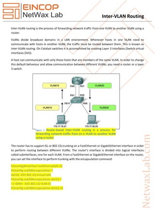
Inter-VLAN routing is the process of forwarding network traffic from one VLAN to another VLAN using a router. VLANs divide broadcast domains in a LAN environment. Whenever hosts in one VLAN need to communicate with hosts in another VLAN, the traffic must be routed between them. This is known as inter-VLAN routing. On Catalyst switches it is accomplished by creating Layer 3 interfaces (Switch virtual interfaces (SVI)).

Recomendados
Más contenido relacionado
La actualidad más candente
La actualidad más candente (20)
Destacado
Destacado (20)
Similar a Inter VLAN Routing
Similar a Inter VLAN Routing (20)
Más de Netwax Lab
Más de Netwax Lab (20)
Último
Último (20)
Inter VLAN Routing
- 1. Inter-VLAN Routing Inter-VLAN routing is the process of forwarding network traffic from one VLAN to another VLAN using a router. VLANs divide broadcast domains in a LAN environment. Whenever hosts in one VLAN need to communicate with hosts in another VLAN, the traffic must be routed between them. This is known as inter-VLAN routing. On Catalyst switches it is accomplished by creating Layer 3 interfaces (Switch virtual interfaces (SVI)). A host can communicate with only those hosts that are members of the same VLAN. In order to change this default behaviour and allow communication between different VLANs, you need a router or a layer 3 switch. The router has to support ISL or 802.1Q trunking on a FastEthernet or GigabitEthernet interface in order to perform routing between different VLANs. The router’s interface is divided into logical interfaces called subinterfaces, one for each VLAN. From a FastEthernet or GigabitEthernet interface on the router, you can set the interface to perform trunking with the encapsulation command: R1(config)#interface FastEthernet0/0.10 R1(config-subif)#encapsulation ? dot1Q IEEE 802.1Q Virtual LAN R1(config-subif)#encapsulation dot1Q ? <1-4094> IEEE 802.1Q VLAN ID R1(config-subif)#encapsulation dot1Q 10 Figure 1 Router-based Inter-VLAN routing is a process for forwarding network traffic from on e VLAN to another VLAN using a router
- 2. Inter-VLAN Routing All Catalyst multilayer switches support the following types of layer 3 interfaces: 1. Routed port- a pure layer 3 port similar to that on a router. 2. Switch virtual interface (SVI)- virtual routed VLAN interface for inter-VLAN routing. 3. Bridge virtual interface (BVI)- a layer 3 bridging interface. Figure 2 The router supports one Vlan per interface Figure 3 A single ISL link can support multiple VLANs
- 3. Inter-VLAN Routing Router Interface and Subinterface Comparison a. Port Limits b. Performance c. Access ports and Trunk ports d. Cost e. Complexity Physical Interface Subinterface One Physical interface per VLAN One Physical interface for many VLAN No bandwidth contention Bandwidth contention Connected to access mode switch port Connected to trunk mode switch port More expensive Less expensive Less complex connection configuration More complex connection configuration There are 3 inter-VLAN routing device options 1. Layer 3 multilayer Catalyst switch 2. External router that allows trunking (router-on-a-stick) 3. External router with enough interfaces for every VLAN (this doesn’t scale and is very expensive) Inter-VLAN Routing Types Figure 4 Inter VLAN Implementation
- 4. Inter-VLAN Routing External Router (Router-on-a-Stick) A layer two switch can be connected to a single router to allow inter-VLAN communication either using a single physical link as a trunk with multiple sub-interfaces (a.k.a. router-on-a-stick) or using seperate physical links between the switch and router for each individual VLAN. Configuring Router-on-a-Stick a. Enable trunking on the switch port b. Enable the router interface with the no shut command c. Create the subinterfaces on the router for each VLAN d. Configure IPs and encapsulation on each subinterface as they relate to their VLANs Switch (conf-subif)# encapsulation [dot1q | isl] vlan-id {native} Switch (conf-subif)# ip address x.x.x.x x.x.x.x Example router interface configuration Router(config)# interface FastEthernet0/0 Router(config-if)#no shutdown Router(config)# interface FastEthernet 0/0.1 Router(config-subif) description VLAN 1 Router(config-subif)# encapsulation dot1Q 1 native Router(config-subif)# ip address 10.1.1.1 255.255.255.0 Router(config-subif)# exit Router(config)# interface FastEthernet 0/0.2 Router(config-subif)# description VLAN 2 Router(config-subif)# encapsulation dot1Q 2 Router(config-subif)# ip address 10.2.2.1 255.255.255.0 Router(config-subif)# exit Router(config)# end Example switch trunk interface configuration (connected to router’s Fa 0/0) switch(config)# interface FastEthernet 4/2 switch(config-if)# switchport trunk encapsulation dot1q switch(config-if)# switchport mode trunk Advantages 1. Works with almost all switches because the switches do not have to support layer 3, just VLANs and trunking. 2. Simple configuration (one switch port, one router interface).
- 5. Inter-VLAN Routing Disadvantages 1. Router is a single point of failure. 2. If the trunk becomes congested, it can affect every VLAN. 3. Slightly higher latency because- -traffic must leave and re-enter the switch. -the router makes the traffic decisions in software (which is slower than hardware). Switch Virtual Interfaces SVIs are virtual VLAN interfaces on multilayer switches; one SVI is created for each VLAN to be routed and it performs the process for all the packets associated with that VLAN. Configuring SVIs a. Enable IP routing b. Create the VLANs c. Create the SVI d. Assign an IP address to each SVI e. Enable the interface f. Optional – Enable an IP routing protocol Example Configuration Switch# configure terminal Switch(config)# ip routing Switch(config)# vlan 10 Switch(config)# interface vlan 10 Switch(config-if)# ip address 10.10.1.1 255.0.0.0 Switch(config-if)# no shutdown Switch(config)# router rip Switch(config-router)# network 10.0.0.0 SVIs are commonly used for: 1. Default gateways for users within the VLAN 2. Virtual route between VLANs 3. Provides an IP address for connectivity to the switch itself 4. Can be used as an interface for routing protocols An SVI is considered “up” when at least one interface in its associated VLAN is active and forwarding traffic. If all interfaces within that VLAN are down, the SVI goes down to prevent creating a routing loop.
- 6. Inter-VLAN Routing Advantages 1. Fast because all performed in hardware 2. No need for external links for routing 3. Low latency (doesn’t need to leave the switch) Disadvantages 1. May require a more expensive switch. Routed Ports Routed Ports are physical ports on the switch that act much like a router interface with an IP address configured. Routed Ports are not associated with an particular VLAN and do not run layer 2 protocols like STP or VTP. (Note: Routed interfaces also do not support subinterfaces.) Routed ports are point-to-point links that usually connect core switches to other core switches or distribution layer switches (if the distribution layer is running layer 3). They can also be used when a switch has only a single switch port per VLAN or subnet. Make sure when configuring a routed port that you use the no switchport command to make sure the interface is configured to operate at layer 3. Also make sure to assign an IP addresses and any other layer 3 information required. Lastly, check that the appropriate routing protocols are configured. A multilayer switch can have both SVIs and routed ports configured. Multilayer switches forward all layer 2 and 3 traffic in hardware, so it is very fast. Configuring Inter-VLAN Routing with Routed Ports 1. Select the interface 2. Convert to layer 3 port (no switchport command) 3. Add an IP address 4. Enable the interface (no shut command) Example Configuration Core(config)# interface GigabitEthernet 1/1 Core(config-if)# no switchport Core(config-if)# ip address 10.10.1.1 255.255.255.252 Core(config-if)# exit
- 7. Inter-VLAN Routing Multilayer Switching A Multilayer switch can perform both layer two switching as well as inter-VLAN routing. While I spend a considerable amount of time walking through the low-level details here, Cisco thinks it is really important. It’s also easy for Cisco to ask SWITCH exam questions on (like the order of operations), so take your time and make sure you understand the process. Knowing the order of events within the switch will help you understand how the many forwarding and filtering options interact. Cisco Express Forwarding Multilayer Switching, or MLS, is a fairly general term used to describe features that enable very efficient routing of traffic between VLANs and routed ports. Cisco Express Forwarding, or CEF, is the specific implementation of MLS Cisco uses on their multilayer switches. Layer 2 Forwarding Process Input Output 1. Receive frame Apply outbound VLAN ACL 2. Verify integrity Apply outbound QoS ACL 3. Apply inbound VLAN ACL Select outbound port 4. Lookup destination MAC Place in port queue 5. Rewrite 6. Forward frame Layer 3 Forwarding Process Input ROUTING Output 1. Receive frame Apply input ACL Apply outbound VLAN ACL 2. Verify integrity Switch if entry is in CEF cache Apply outbound QoS ACL 3. Apply inbound VLAN ACL Identify exit interface and next hop address using routing table Select outbound port 4. Lookup destination MAC Apply outbound ACL Place in port queue 5. Rewrite 6. Forward frame