
Recommended
More Related Content
What's hot
What's hot (20)
Similar to Pile foundation
Similar to Pile foundation (20)
More from Parth Desani
More from Parth Desani (20)
Recently uploaded
Recently uploaded (20)
Pile foundation
- 2. Content Uses ,selection of pile and types of piles Pile spacing ,Group of piles and Efficiency of group of piles Pile Cap and Pile shoe ,load tests on piles, pile driving and pulling of piles Loads on piles, causes of failures of piles, pile driving formulas.
- 3. introduction 3 Foundations are structural components used to support columns and transfer loads to the underlying Soil. Foundation s Isolated Combined Strap wall Raft Shallow footing footing footing footing footing Caissons Piles Deep
- 4. When the depth of foundation is more then the width of foundation ,then it is termed as deep foundation. If the desired soil bearing capacity is not available at shallow depth, the foundation of the structure is to be taken to a more depth. The deep foundations are classified as below: Pile foundation Cofferdams Caissons Pile foundations are used extensively for the support of buildings, bridges, and other structures to safely transfer structural loads to the ground and to avoid excess settlement or lateral movement. They are very effective in transferring structural loads through weak or compressible soil layers into the more competent soils and rocks below.
- 5. PILE FOUNDATION… • A slender, structural member consisting steel or concrete or timber. • It is installed in the ground to transfer the structural loads to soils at some significant depth below the base of the structure.
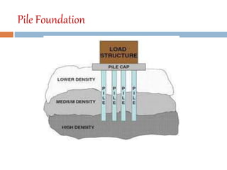
- 6. Pile Foundation 6 Our building is rested on a weak soil formation which can’t resist the loads coming from our proposed building, so we have to choose pile foundation. Pile cap Piles Weak soil Bearing stratum Piles are structural members that are made of steel, concrete or timber.
- 7. 7 Function of piles As with other types of foundation, the purpose of a pile foundation is: To transmit a foundation load to a solid ground To resist vertical, lateral and uplift load Piles can be Timber Concrete Steel Composite
- 8. Uses of piles The load of the superstructure is heavy and its distribution is uneven. The top soil has poor bearing capacity. The subsoil water is high so that pumping of water from the open trenches for the shallow foundations is difficult and uneconomical. There is a large fluctuation in subsoil water level. Where timbering to the trenches is difficult and costly. The structure is situated on the sea shore or river bed, where there is danger of scouring action of water. canal or deep drainage lines exist near the foundations. The top soil is of expansive nature. Piles are used for the foundations of transmission towers, off- shore platforms which are subjected to uplift forces.
- 10. Pile applications Soft to Firm Clay Strong Rock
- 11. Factors affecting the selection of type of piles Nature of structure Loading conditions Availability of funds Availability of materials and equipments Types of soil and its properties Ground water table Self weight of pile Durability of pile Cost of pile Maintenance cost Length of pile required Number of piles required Facilities available for pile driving Presence of acids and other materials in the soil that would injure the pile
- 12. Types of Piles Based on Function a) Classification based on Function or Use 1. Bearing Piles or End Bearing Piles 2. Friction Piles or Skin Friction Piles 3. Sheet Piles 4. Tension Piles or Uplift Piles 5. Anchor Piles 6. Batter Piles 7. Fender Piles 8. Compaction Piles
- 13. Types of Piles Based on Materials b) Classification based on Materials 1. Timber Piles 2. Concrete Piles 3. Composite Piles 4. Steel Piles 5. Sand Piles
- 14. Pile materials SteelTimber ConcreteTimber Steel H Composite Pre-cast Concrete Concrete Steel Pipe
- 15. Types of Piles Based on Method c) Classification based on Method 1. Driven Piles 2. Driven and cast-in-situ Piles 3. Bored and cast-in-situ Piles 4. Screw Piles 5. Jacked Piles
- 16. Classification of piles (based on function or use) <1> END BEARING PILE These piles penetrate through the soft soil and their bottoms or tips rest on a hard stratum. These piles act as columns. The soft material surrounding the pile provides some lateral support. For end bearing pile Qu = Qp. <2> FRICTION PILE When loose Soil extends to a great depth, piles are driven up to such a depth that frictional resistance developed at the sides of the piles equals the load coming on the piles. Friction piles are used when a hard stratum is available at a greater depth. For friction pile Qu = Qs where Qu = ultimate load & Qs = skin friction
- 17. Classification of piles (based on function ) <3> COMPACTION PILE When piles are driven in loose granular soil with the aim of increasing the bearing capacity of soil, the piles are termed as compaction piles. These piles themselves do not carry any load. <4> TENSION PILE These piles anchor down the structures subjected to uplift due to hydrostatic pressure or due to overturning moment. It is also called uplift pile.
- 18. Classification of piles (based on function ) <5> FENDER PILE Fender piles are used to protect water structures against impact from ships or other floating objects.
- 19. Classification of piles (based on material ) 19 Piles Concret e Pile Steel Pile Timber Pile Composit e Pile Sand Pile
- 21. 1. Pre Cast concrete pile Precast concrete piles are those which are manufactured in a factory or at a place away from the construction site and then driven into the ground at the place required. These piles require heavy pile driving machinery. Precast piles may be square, octagonal or circular in cross section. The size of piles may vary from 30 cm to 50 cm in cross sectional dimension, and up to 20 m or more in length. The reinforcement may consist of longitudinal steel bars of 20 mm to 40 mm in diameter, 4 to 8 nos. with lateral ties of 6 to 10 mm diameter at 100 mm c/c spacing. A concrete cover of at least 50 mm is provided. The grade of concrete should be M20.
- 24. Procedure for forming precast concrete piles The formwork for the pile is prepared and it is coated with soap solution or oil to prevent adhesion. The cage of reinforcement is prepared as per design and this cage is then placed in the formwork. A concrete cover of at least 50mm is provided. A concrete of grade M20 is prepared with proportion 1:1.5:3. The size of coarse aggregate varies from 10 mm to 25 mm. The forms are removed after 3 days and the piles are kept in the same position for about 7 days or so. The piles are then shifted to a curing tank and after a period of about three or four weeks, they become ready for use.
- 25. 2.Cast-in-situ Concrete Pile 25 Cast-in-situ Concrete Piles Uncased Simplex pile Franki Pile Vibro pile Pedestal pile Pressure Pile Cased Raymond pile Mac Arthur Pile Monotube Pile BSP base driven piles Swage piles
- 26. RAYMOND PILE The Raymond standard pile is used primarily as a friction pile. It is provided with uniform taper of 1 in 30 resulting in shorter piles. The lengths of piles vary from 6 to 12 m. The diameter of piles vary from 40 to 60 cm at the top and 20 to 30 cm at the bottom. Raymond piles have a high bearing capacity, because of the corrugated surface of the pile shaft and their conical pile shape. They are suitable for high pile loads and difficult driving conditions.
- 28. Raymond Pile installation In Raymond Pile installation shell is closed at bottom. The shell is driven in to ground with a collapsible steel mandrel or core in it having the same taper. When the pile is driven in to the desired depth, the mandrel is mechanically collapsed and withdrawn, leaving the shell inside the ground. The shell is inspected internally by using the light from a mirror of flash light or drop light. The shell is gradually filled with concrete up to the top.
- 29. Mac-Arthur piles These pile is a pile of uniform diameter, using the corrugated steel shell which remain in place. However, the driving of the pile uses an additional steel casing of heavy gauge (thickness). The heavy steel casing with a central core is driven into the ground as shown in the figure. After reaching the desired depth the central core is withdrawn and a corrugated shell is placed in the casing. Finally concrete is placed in the shell by gradually compacting it and withdrawing the steel casing. The compacted pile contains concrete core and the outer corrugated shell.
- 31. Montube piles Montube piles use tapered fluted steel shell without mandrel, and are suitable for wide variety of soil conditions, from end bearing to friction load carrying soils. The shell provide rigidity, and are watertight. The pile shells are driven to the required depth, and they are inspected after driving . Shells may be driven with hammer of comparable size to those used for wood piles. The shell, after inspection is filled with concrete and the excess length of shell is cut.
- 32. Swage piles A pipe pile, having a thin wall; the bottom of the pipe is closed with a precast point. Swage Piles are used with advantage in some soils where the driving is very hard or where it is designed to leave water tight shell for some time before filling the concrete. The four stages of forming these piles are shown i In the first stage (a), a thin steel pile (known as Shell) is placed on a precast concrete plug, and a steel core, which is not long enough to reach the plug is inserted in the shell. In the second stage (b), as the pipe is driven over the plug until the core reaches the plug, the pipe is swaged out by the taper of the plug, thus forming a water tight joint. In the third stage (c), the pipe is driven to a specified depth. The driving force is practically all exerted by the core on the plug and the pipe pulled down rather than driven. In the froth stage (d), after the pipe has reached the desired depth, the core is removed, and the pipe left open until it is desired to fill it. In the final stage (e), the pipe is filled with concrete.
- 33. Button-bottom Pile These piles are used in locations where increase in the end bearing area is desired. The pile uses a concreteplug,of the shape of a button. this button forms an enlarged hole in the soil during driving. The four stages in the pile driving are shown. In the first stage a steel pipe with 12mm thick walls and reinforced base of cast steel, is set over the concrete button. the concrete button has a diameter about 25mm larger than the pipe. In stage the pipe and button are driven to a specified depth. In the third stage a corrugated steel shell is inserted in the pipe, resting on the button. A steel plate with a bolt hole in it is welded on the bottom of the shell, before lowering it, so that hole may fit over the central bolt in button bottom. In the fourth stage the casing is withdrawn, leaving the button in place and the shell is filled with concrete.
- 34. Uncased cast in situ concrete piles: These piles are comparatively cheap, as no casing will be left in the ground. But, great skill is required in this case to achieve the desired results. The common types of uncased cast in situ concrete piles are: 1. Simplex piles 2. Franki piles 3. Vibro piles 4. Pedestal piles 5. Pressure piles
- 35. Simplex pile In this type of pile, a steel tube is fitted with cast-iron shoe is driven in to the ground up to the desired depth. The Reinforcement, if necessary is placed in the tube. The concrete is poured into the tube and the tube is slowly withdrawn, leaving the shoe into the ground. The concrete is not tamped and the pile is completed such a pile is known as simplex standard pile. If tampering of concrete is done at regular intervals as the tube is withdrawn, it is known as simplex tamped pile.
- 36. Franki pile The Franki pile, known and used world wide, It is a cast-in-situ concrete pile with an enlarged base and a cylindrical shaft which, due to its powerful driving method during installation, can penetrate stiff soils and reach large depths. By expulsion of a dry concrete plug, the soil surrounding the pile base is improved and thus the initial soil bearing capacity can be increased significantly. Although the application of the Franki system has decreased due to cost and environmental considerations, this system is still competitive and widely used when site conditions are suitable.
- 37. Franki pile This pile has an enlarged base of mush- room shape, which gives the effect of a spread footing. Also this type of pile is best suited to granular soil. Figure shows various stages of pile. In the first stage a heavy removable pipe shell is set vertically on the ground with the help of leads and a charge of dry concrete or gravel is formed. In the second stage a diesel operated drop hammer of 20 to 30 kN weight is driven on the concrete. In the third stage when the tube has reached the desired depth, the tube is held in position by cables and the hammer is applied to the concrete, forcing it down and outward. In the fourth stage the shaft is formed by introducing successive charges of concrete, ramming each in turn and withdrawing gradually the casing. Finally it shows formed pile which has
- 38. Vibro pile The Vibro piles are formed by driving a steel tube and a casi iron shoe, filling with concrete and extracting the tube using upward extracting and downward tamping blows alternatively. Vibro-piles are extremely suitable for a large variety of soil conditions, for which the pile length can be adapted to the supporting capacity of the subsoil. This avoids risks of having piles too long or too short. A Vibro-pile is a closed off casing that is vibrated into the ground displacing and "densifying" all the material in its path. The casing is then filled with concrete and reinforcement and then extracted (or filled with concrete as it is extracted and the reinforcement is installed later. Vibro-pile is used as an alternative to pre-cast piles or drilled cast- in-situ piles in soft grounds especially when vibrating a can/probe is faster than drilling and casing or when vertical tie downs are necessary.
- 39. Pedestal piles This type of piles are used where the bearing stratum is reached with reasonable depth. The pedestal of the pile gives the effect of spread footing on this comparatively thin bearing. The core and casing are driven together into the ground, till they reach the desired level. The core is taken out and a charge of concrete is placed in the tube. The core is again placed in the casing to rest on the top of poured concrete. Pressure is applied on the concrete through the core, and as the same time, the casing is withdrawn. The process is repeated till the casing is completely removed.
- 40. Pressure piles These are formed with the help of a casing tube, boring auger and compressed air equipment. these piles are especially suitable for those congested sites where heavy vibrations and noise are not permissible. A hole is bored into the ground by means of an auger and as the boring proceeds, the hole is lined by a steel tube. When the tube reaches the required depth, the boring tool is withdrawn. the reinforcement, if any is then placed in the tube. In the second stage, a layer of concrete is laid and pressure cap is provided at the top of the tube. Compressed air is then admitted through the air pipe and which is applied to raise the tube.Thus,the pile is lifted slightly and at the same time concrete is forced into the surrounding ground by compressed air. The process is repeated till the pile is completed. care should taken to see that some portion of concrete remains at the bottom of tube when lifting of tube is stopped to receive a new layer of concrete.
- 41. SHEET PILES Sheet piles are thin piles, made of plates of concrete, timber or steel, driven into the ground for either separating members or for stopping seepage of water. They are not meant for carrying any vertical load. Therefore, sheet piles are also termed as non-load bearing piles. Sheet piles are used for the following purposes: (1) To isolate foundations from adjacent soils. (2) To prevent underground movement of water. (3) To prevent the transfer of machine vibrations to adjacent structures. (4) To construct retaining walls in docks, wharfs and other marine Structures. (5) To protect river banks. (6) To retain sides of foundations trenches. (7) To work as cutoff walls under dams. (8) To confine the soil and thereby increase the bearing capacity of soil. (9) To construct caissons for water-intake structures.
- 42. SHEET PILES Based on the material, types of sheet piles are: 1. Concrete sheet piles 2. Steel sheet piles 3. Timber sheet piles 1.Concrete sheet piles : Concrete sheet piles are reinforced, precast units. The width of each unit may vary from 50 cm to 60 cm and thickness varies from 2 cm to 6 cm. The rainforcement is in the form of vertical bars and hoops. For important works, Pre-stressed precast concrete piles are used.
- 43. SHEET PILES Pre-cast RCC sheet piles are used for permanent work such as bulk Heads, cut-off wails, retaining walls, wharf walls, etc. In order to make them water tight, they are placed in such a way that Grooved are formed and these grooves are then filled by cement mortar In proportion (1 : 3) under pressure. The feet of the piles are shaped obliquely and beveled so as To facilitate driving. Metal shoes are provided at the bottom of the piles, If they have to pass through hard strata. 2. Steel sheet pile: Steel sheet piles are most commonly used. They are trough shaped and when the piles are interlocked with alternate once reversed. They are generally made from steel sheets 20 to 30 cm wide and 4 to 5
- 44. SHEET PILES Steel sheet piles are strong and durable and can be easily driven without appreciable distortion. They provide a fairly water tight enclosure and hence, they are widely used in the construction of cofferdams. They are also used for permanent works in marine structures.
- 45. SHEET PILES Different types of steel sheet piles are: 1. Arch web steel sheet pile. 2. Built up steel sheet pile. 3. Z-type steel sheet pile. 4. Corrugated steel sheet pile. 5. Deep arch web steel sheet pile. 6. Universal joint steel sheet pile. Universal joint steel sheet piles consists of I-beams connected by standard clutches or lock bars. The clutch is also of I-beam. But its flanges are curved so as to accommodate the flanges of I-beams. 3. Timber sheet piles: Timber sheet piles are commonly y used for temporary works Such as Cofferdams.
- 46. SHEET PILES The width of the sheet may Vary from 225 to 280 mm, while thickness should not be less than 50 mm. They may be jointed by either butt or V-joints. Their feet are beveled and sometimes Shod with sheet iron.
- 47. CLASSIFICATION OF SHEET PILES Classification of piles based on method of installation: Based on the method of installation Piles may be classified as follows: 1. Driven piles: These Piles are driven into the ground by applying blows with a heavy hammer on their tops. Timber, steel and precast concrete Piles are installed by driving. which may be driven into position either vertically or at an inclination. 2. Driven and cast in situ Piles: These Piles are formed by driving a casing with a closed bottom end into the soil. The casing is later filled with concrete. The casing may or may not be withdrawn. 1f casing is withdrawn, it is called uncased Pile, and if casing is withdrawn, it is called uncased pile, and if casing is not withdrawn, it is called cased Pile. 3. Bored and cast in situ piles: These piles are formed by excavating a hole into the ground and then filling it with concrete.
- 48. 4. Screw piles: These piles are screwed into the soil. 5. Jacked piles: These piles are jacked into the ground by applying a downward force with the help of hydraulic jack. Under reamed piles: These piles are successfully developed by C.B.R.I., Roorkee (U.P.) for serving as foundations for black cotton soils, filled up ground and other types of soils having poor bearing capacity. An under reamed is bored cast-in-situ concrete pile having one or more bulbs or under-reams in its lower portion. The bulbs or under-reams are formed by under reaming tool. The diameter of under reamed pile varies from 20cm to 50cm and that of bulb varies from 2 to 3 times the diameter of pile.
- 49. Under reamed piles The length of under reamed piles is about 3m to 8m. The spacing of piles may vary from 2m to 4m. The under reamed piles can be used for sandy soils with high water table. The load bearing capacity of under reamed piles can be increased by adopting piles or larger diameter or by extending the length of piles or by making more bulbs at the base. A single under reamed pile has only one bulb at the bottom. When two or more bulbs are provided at the base, It is known as multiple under reamed pile. The vertical spacing between two bulbs varies from 1.25 to 1.50 times the diameter of bulb.
- 50. Under reamed piles In case of black cotton soils, the bulbs, not only increase the bearing capacity, but also provide anchorage against uplift. Figure Shows various stages in the formation of a under reamed pile. The equipment required for the construction of pile are (i) auger boring guide, (ii) spiral auger with extension rods, (iii) under reamer with soil bucket, (iv) concreting funnel.
- 51. Pile spacing The spacing of pile is the center to center distance between two successive piles. The factors to be considered while deciding the pile spacing are as follows: 1. The nature of soil through which the pile is driven 2. The obstruction during pile driving 3. The type of pile 4. The depth of penetration 5. The area of cross section of the pile 6. The centre to centre distance of piles in a group
- 52. Group of piles Sometimes the piles are arranged in close- spaced groups. When the piles are driven to the required depth, their tops are cutoff a same level and then the pile cap is provided. The piles forming the group of piles may be arranged in square, rectangular, triangular or circular as per the requirement. In case of single pile small pressure is developed in the surrounding soil. And in case of group piles, the pressure developed surrounding the individual piles will overlap laterally and the pressure in the overlapping zone will be sufficient to cause movement of the soil and consequently the pile will settle down.
- 53. Pile Accessories In case of wooden piles, steel piles, pre-cast concrete piles, to protect the top and bottom of the pile while driving in to the ground and to facilitate easy pile driving certain accessories are required as under : 1. Pile Cap 2. Pile Shoe
- 54. 1. Pile Cap In case of driven pile, piles are driven in to the ground by applying blows of a heavy hammer on their tops. Thus, to protect the top of pile, pile cap is provided. Normally, pile cap is made of steel. The thickness and size of pile cap depends upon the shape and size of the pile driving hammer. The pile should penetrate into the cap for at least 10 cm length. In case of group of piles, a common cap of R.C.C. is provided for all the piles.
- 55. 2.Pile Shoe While driving wooden or steel pile by hammer the bottom end of the pile gets damaged causing difficulty in driving. Therefore, a pile shoe is fitted at the bottom end of the pile to protect the pile and to facilitate easy pile driving. Pile shoe are made of cast iron, steel iron.
- 56. Accessories of piles Various Types of Pile Shoe : 1. Square Pile Shoe 2. Wedge shape Shoe 3. Round Pile Shoe 4. Steel Trap shoe 5. Socket Type pile shoe 6.Closed end shoe for pipe pile.
- 57. Pile Driving The operation of inserting a pile into the ground is known as pile driving. Points to be considered for selection of pile driving method: Various Methods of Pile driving : Hammer driving Vibratory pile driver Water jetting and hammering Partial augering method
- 58. Hammer driving Pile frame Pile hammer Leads Winches Miscellaneous equipements.
- 59. Vibratory pile driver Drop hammer Single acting hammer Double acting hammer Diesel hammer
- 60. Single Acting Hammer Features External compressor supplies power Stroke controlled by 1 or 2 slide bar setting: 3 ft, 3 or 5 ft, 2 or 4 ft Comments Air pressure, volume, and soil resistance can influence actual stroke by as much as 3 to 6 inches Relatively heavy ram, short stroke
- 61. Drop Hammer Features Ram raised by crane line Efficiency of drop controlled by operator and system Comments • Low equipment cost • Simple• Slow operation • Inconsistent stroke
- 62. Diesel Hammer Comments Stroke depends on: • fuel input • pile stiffness • soil resistance Variable fuel settings Potential energy = Wh Most common hammer type Relatively light ram, long stroke
- 63. Double Acting Hammer Features Weight of hammer about 1000- 2500kg Can apply 90-240 blows per min Generally used for driving light to moderate weight piles Comments Skin friction between successive blows is reduced due to number of blows Reduction of time of driving piles
- 64. Water jetting and hammering The use of a water or air jet to facilitate pile driving by displacing parts of the soil Jetting is useful in driving piles through very dense granular material
- 65. Loads on Piles Direct vertical load coming from super structure. Impact stresses developed during the process of pile driving Stresses developed during handling operation. Bending stresses developed due to eccentricity of loads coming on the pile. Lateral forces due to wind, waves , currents of water etc. Impact forces due to the ice sheets or begs. Impact forces due to ships, in case of marine structures. Forces due to uplift pressure. Earthquake forces etc.
- 66. Causes of Failure of piles Absence of statistical data regarding the nature of soil strata through which the piles are to be driven. Actual load coming on the pile being more than the design load. Bad workmanship in case of the cast-in-situ cement concrete piles. Attack by insets, etc. on wooden piles. Breakage due to over driving especially in case of the timber piles. Buckling of piles due to removal of side support, inadequate lateral support, etc.
- 67. Causes of failure of pile Lateral forces (wind, waves, currents etc.) not being taken into the design of the pile. Improper choice of the type of pile. Improper choice of the method of driving the pile. Improper classification of pile. Insufficient reinforcement or misplacement of reinforcement in case of the R.C.C. piles. Wrongful use of pile formula for determining its load bearing capacity.
- 68. Pile load Test Preliminary pile design is first carried out on the basis of site investigations, laboratory soil testing, and office study. Pile load tests are then carried out to refine and finalize the design. For these conditions, the test piles are generally tested to failure.
- 69. Construction Bearing plate Anchor piles Anchor girder Hydraulic jack Reference beam Dial gauge
- 70. Method Load the pile in eight equal increments (Le., 25 percent, 50 percent, 75 percent, 100 percent, 125 percent, 150 percent, 175 percent, and 200 percent) to 200 percent of the design load. Maintain each load increment until the rate of settlement has decreased to 0.01 in./h (0.25 mm/h) but not longer than 2 h. Maintain 200 percent load for 24 h. After the required holding time, remove the load in decrements of 25 percent with 1 h between decrements. After the load has been applied and removed, as above, reload the pile to the test load in increments of 50 percent of the design load, allowing 20min between load increments.
- 71. Graph Sn = St – Se, Where, Sn=net settlement St=total settlement Se=elastic settlement.
- 72. Pulling of Piles Features: To replace damage pile during driving operation To change design and arrangement of piles. To prepare data of strata of pile driving. Removal of piles.
- 73. Methods Commonly Adopted Use of double acting hammer:- worked in reversed way, steady pull of 4Nmm2 is applied Use of pile extractors:- Easily put up in to use , does not require any special fitting.
- 74. Use of tongs:- Suspended from frame and a pull of 50 N/mm2 is applied Use of electricity:- Apply of direct current voltage leads to attraction of water causing lubrication of steel pipe, hence skin friction reduces.
- 75. Pile Driving Formulae Dynamic formulae 1. Engineering news record formula 2. Hiley’s formula 3. Danish formula Static formulae
- 76. Dynamic Formulae Kinetic energy delivered=work done in penetration Whηh = R X S + energy losses Where, W= weight of hammer (KN) h= height of fall of hammer ηh =efficiency of hammer R= pile resistance S= penetration of pile per blow
- 77. Engineering news record(ENR) Formulae Qa = Qa= allowable load W= weight of hammer h= height of fall of hammer F= factor of safety=6 S= penetration per blow C= emperical constant = 25 mm for drop hammer = 2.5 mm for single acting and double acting steam hammer Wh F( S + c )
- 78. Engineering news record(ENR) For drop hammer Single acting steam hammer Double acting steam hammers a= effective area of piston p= mean effective steam pressure Qa = Qa = Qa =
- 79. Hiley’s Formulae Qu= ultimate load on pile W = weight of hammer h= height of fall of hamer C= total elastic compression =C1+C2+C3 ηh= efficiency of hammer S = average settlement per blow Qu = Drop hammer (ηh=100%) Single acting hammer ( ηh=75- 85%) Double acting hammer (ηh= 85%)
- 80. Danish Formulae Where, S0= elastic compression of piles S = Penetration per blow L=length of pile A= cross sectional area of pile E= modulus of elasticity F= factor of safety=3 Qu = So= Qa=
- 81. Static Formula Qu=ultimate bearing load Qp=end bearing resistance Qs=skin friction resistance qp= unit end bearing resistance =ultimate bearing capicity Ap =area at base Fs= unit skin friction As=surface area of pile in contact of soil Qu=Qp +Qs Qp=qp Qs= fs . As
- 82. Micro Piles
- 83. Micro Piles construction Sequence Drilling or installation of temporary casing Remove inner drilling bit and rod Placing reinforcement and grouting it Remove temporary casing, inject further grout under pressure Complete pile
- 85. Classification of Micro Piles 1.Design Behaviour (Case 1 and Case 2) 2. Method of Grouting (Type A, B, C, D, E )
- 86. Classification of Micro Piles 1.According to Design Application (Case - 1) Each Micro pile is Loaded Directly Primary Resistance is Provided by Steel Reinforcement and Side Resistance over Bond Zone Each Micro pile Designed to Act Individually, Even When in Groups
- 88. Classification of Micro Piles 1.According to Design Application (Case – 2 ) Network of Micro piles Act As Group to Reinforce The Soil Mass Each Micro pile is Lightly Reinforced Design Procedures Not Fully Developed
- 90. 2.According to Method of Grouting
- 92. Drilling Techniques of Micro Piles Single Tube Advancement Rotary Duplex Rotary Percussion Concentric Duplex Rotary Percussion Eccentric Duplex Double Head Duplex Hollow Stem Auger
- 93. Duplex Casing and Roller Bit Rotary Eccentric Percussive Duplex
- 94. Grouting Purpose : Transfer of load from reinforcement to surrounding ground Part of micro pile load-bearing cross section Protect steel reinforcement Extend the limits of the drill hole by permeation, densification
- 95. Grouting General Characteristics : High strength and stability Use potable water to reduce potential for corrosion; Neat water-cement grout mix most common; Design compressive strengths Admixtures/additives used, must be compatible, one supplier only;
- 96. Grouting Most Important Considerations: Water/cement (w/c) ratio 0.40 to 0.50;Pre-construction testing, specifications , construction monitoring After completion of grouting, no significant loss of grout in load bearing zone, Monitor grout take, grout to refusal, pre- grout, re-grout For Type B micro piles, consider possibility that target pressure may not be fully obtained during installation include verification load test program and proof testing of suspect piles in specifications
- 97. Grouting
- 98. questions Q-1 Explain the situations in which pile foundations are used? Q-2 Discuss the main factors affecting selection of type of pile. Q-3 Explain with sketches the method of forming button bottom pile & simplex pile. Q-4 Describe precast concrete pile with sketches, process of casting advantages & disadvantages. Q-5 What are the factors considered while deciding the pile spacing? Q-6 Explain the behaviour of a single pile & piles in group under the load. Q-7 Describe in brief, various type of pile driving equipments with sketches of each. Q-8 Explain the dynamic formulae adopted for determining load carrying capacity of a pile. Q-9 Make a comparison between Cast-in-situ piles & Pre-cast
- 99. Thank you