Transmission system
•Download as PPTX, PDF•
7 likes•649 views

Introduction to the Transmission system, Requirements of the transmission system, main units of the transmission system, types of the transmission system, clutch, functions of a clutch, requirements of a clutch, principle of operation of a clutch, friction materials, classification of a clutch, cone clutch, single-plate clutch, multi-plate clutch centrifugal clutch, hydraulic coupling, hydraulic torque converter.

Recommended
More Related Content
What's hot
What's hot (20)
Similar to Transmission system
Similar to Transmission system (20)
More from Ratnadeepsinh Jadeja
More from Ratnadeepsinh Jadeja (20)
Recently uploaded
Recently uploaded (20)
Transmission system
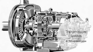
- 1. Transmission System By : Ratnadeepsinh Jadeja
- 2. Introduction to Transmission system • The mechanism that transmits the power developed by the engine of the automobile to the driving wheels is called the transmission system (or power train). • It is composed of the clutch, gear box, propeller shaft, universal joints, rear axle, wheel and tyres. • The vehicle which have front wheel drive in addition include a second set of propeller shafts. Universal joints, final drives and differentials for the front units.
- 4. Requirements of Transmission system • The transmission should fulfill the following requirements: 1. Provide means of connection and disconnection of engine with rest of power train without shock. 2. Provide a varied leverage between the engine and the drive wheels. 3. Provide means to transfer power in the opposite direction. 4. Enable power transmission at varied angles and varied lengths. 5. Enables speed reduction between engine and the drive wheels in the ratio of about 5:1. 6. Enable diversion of power flow at right angles. 7. Provide means to drive the driving wheels at different speeds when required. 8. Bear the effect of torque reaction, driving thrust and braking effort effectively.
- 5. • The above requirements are fulfilled by the following main units of transmission system: 1. Clutch 2. Gear box 3. Transfer case 4. Propeller shaft and universal joints 5. Final drive 6. Differential 7. Torque drive 8. Road wheels.
- 6. Types of Transmission systems 1. Electrical and electromagnetic transmission system 2. Hydraulic transmission system 3. Mechanical transmission system.
- 7. Units of Transmission systems 1. Clutch unit • Clutch assembly or fluid coupling 2. Transmission unit • Gear box • Transfer case • Overdrive • Free wheeling device • Torque converter etc 3. Driving unit • Propeller shaft • Universal joints • Sprockets and chains 4. Driving axle unit • Final drive • Differential • Half shafts etc.
- 8. CLUTCH • A clutch is a mechanism which enables the rotary motion of one shaft to be transmitted at will to second shaft, whose axis is coincident with that of first. • The clutch is “disengaged” when starting the engine, shifting the gears, stopping the vehicle and idling the engine. • The clutch is “engaged” only when the vehicle is to move and is kept engaged when the vehicle is moving.
- 9. Functions of a clutch 1. To permit engagement and disengagement of a gear when the vehicle is stationary and the engine is running. 2. To transmit the engine power to the road wheels smoothly without jolt/shock to the transmission system while setting the wheel in motion. 3. To permit the engaging of gears when the vehicle is in motion without damaging the gear wheels.
- 10. Requirements of a clutch. 1. Engage gradually to avoid sudden shock/jerks. 2. Easily operated (i.e. consume minimum physical effort) 3. Dynamically balanced (particularly required in case of high speed engine clutches) 4. Free from slip when engaged. 5. As small as possible so that it will occupy minimum space. 6. Wearing surface should have long life. 7. Easily accessible and have simple means of adjustment. 8. Suitable mechanism to damp vibrations and to eliminate noise produced during the power transmission. 9. Able to dissipate large amount of heat which is generated during the clutch operation due to friction. 10. Driven members of the clutch should be made as light as possible. 11. Should have Free pedal play in order to reduce effective clamping load on the carbon thrust bearing and wear on it.
- 11. Principle of Operation of a Clutch • The clutch principle is based on friction. When two friction surfaces are brought in contact with each other and pressed they are united due to friction between them. • The friction between two surfaces depends upon, 1. area of the surface, 2. pressure applied upon them, 3. coefficient of friction of the surface materials.
- 12. Friction Materials 1. Woven type is made by spinning threads from asbestos fibers, some times on brass wire, weaving this thread into cloth and then impregnating it with a bonding material (such as vegetable grains, rubber, synthetic resins etc.). 2. The moulded or compression type of lining is composed of asbestos fibers in their natural state mixed with a bonding material and then moulded in dies under pressure and at elevated temperatures. Metallic wires are sometimes included but only to increase the wearing qualities and to eliminate scoring of the metal faces against which the lining rubs. 3. Mill board type friction materials mainly include asbestos sheets treated with different types of impregnants. They are cheap as well as quite satisfactory in operation.
- 13. Friction Materials The following materials are almost universally used for clutch lining: 1. Leather 2. Cork 3. Fabric 4. Asbestos 5. Reybestos and Ferodo Properties of a good clutch lining: 1. High coefficient of friction. 2. Good wearing properties. 3. Cheap and easy to manufacture. 4. Good binder in it. 5. High resistance to heat.
- 14. Classification of clutches The clutches can be classified as follows: 1. Positive clutches. 2. Gradual engagement clutches.
- 15. Gradual Engagement Clutches In such clutches it is possible for one shaft to be revolving rapidly while the other is either stationary or revolving at lower speed. As the engagement of the clutch proceeds the speed of the two shafts gradually become same, and when the clutch is fully engaged the shafts revolve as one. Such clutches are called friction clutches. Friction clutches are of three type 1. Cone clutch 2. Single plate clutch 3. Multi plate clutch Other forms of clutches 1. Centrifugal and magnetic clutches 2. Fluid flywheel (Fluid Hydraulic coupling) 3. Hydraulic torque converter.
- 17. Cone clutch • The only advantage of cone clutch is that the normal force acting on the friction surface is greater than the axial force, as compared to the single plate clutch is which the normal force acting on the friction surfaces is equal to the axial force. • The cone clutch is practically obsolete, due to the following disadvantages. 1. If the cone angle is made smaller than 20°, the male cone tends to bind in the female cone and it is difficult to disengage the clutch. 2. A small amount of wear on the cone surfaces results in a considerable amount of the axial movement of the male cone for which it will be difficult to allow. • It is only used in the synchromesh units of gear boxes, and in overdrives and some epicyclic gear boxes.
- 18. Single Plate Cutch • Clutch slip occurs if the resisting torque on the driven shafts exceeds the friction torque at the clutch. • Single plate clutch divides in two category of elastic member 1. With helical springs 2. With diaphragm spring (Belle ville springs) • The diaphragm springs offers the following advantages: 1. The operating load is practically uniform and constant on the driven plate. 2. It has a compact design, which results in smaller clutch housing. 3. Release levers are not required, since the diaphragm itself acts as a series of leavers. 4. Squeaks, rattles and vibrations are mostly eliminated. 5. It can withstand higher rotational speeds since the diaphragm is comparatively less affected by the centrifugal forces.
- 21. Multiplate Cutch • When a great amount of torque is to be transmitted instead of single plate we can employ a number of friction plates. This will increase the number of mating surfaces, hence it is called multiplate clutch. • These clutches are used in heavy commercial vehicles, racing cars and motorcycles for transmitting high torque.
- 22. Multiplate Cutch
- 23. Multiplate wet Cutch • It consists of number of thin plates made of steel fitted to the engine shaft and those on gear shaft are made of phosphor bronze. These plates are immersed in a bath of oil and also have grooved surfaces for permitting the oil to flow through them. These grooves help to dissipate the heat generated during the engagement and release operation. • These clutches are generally used in conjunction with or as a part of the automatic transmission. Multiplate dry Cutch • In this type of clutch its different plates are lined with a friction material similar to that used in case of a single plate. • The clutches with metal plates are used in tractors or other light powered engine vehicles.
- 24. Centrifugal Cutch • Centrifugal force, instead of spring force, is used for keeping it in engaged position. Also, it does not require any clutch pedal for operating the clutch. The clutch is operated automatically depending upon the engine speed.
- 25. Centrifugal Cutch • Centrifugal force, instead of spring force, is used for keeping it in engaged position. Also, it does not require any clutch pedal for operating the clutch. The clutch is operated automatically depending upon the engine speed.
- 26. Semi-centrifugal Cutch • Semi centrifugal clutch uses centrifugal force as well as spring force for keeping it in engaged position. The springs are designed to transmit the torque at normal speeds, while the centrifugal force assists in torque transmission at higher speeds. • The centrifugal force on the pressure plate can be adjusted by an adjusting screw provided at the end of the lever.
- 27. Fluid coupling/Fluid flywheel • Fluid coupling is a hydraulic unit that replaces a clutch in a semi or fully automatic system, and transmits the engine torque to a transmission system. Since the coupling is a major part of the engine flywheel assembly, it is also called a fluid flywheel or fluid drive acting as an automatic clutch.
- 28. Fluid coupling/Fluid flywheel • The efficiency of power transmission may be as high as 98 % • The efficiency of the hydraulic coupling is defined as the ratio of power output to power input • The ratio Wt/Wp is known as speed ratio. • A fluid coupling always slips by about 2 to 4 percent when transmitting full load. It means that the turbine is always running slightly slower than the impeller and as such complete disconnection of the drive is not possible. Thus the fluid coupling is not suitable for ordinary gear box and is generally used with epicyclic gears to provide a semi or fully automatic gear box.
- 29. Hydraulic torque converter • Hydraulic torque converter is a device used for transmitting increased or decreased power from one shaft to another. A variable torque is impressed on the driven member without the use of a gear train or clutch.