
Recomendados
Más contenido relacionado
Similar a INSTALACION DE CAUDALIMETRO
Similar a INSTALACION DE CAUDALIMETRO (20)
Último
Último (12)
INSTALACION DE CAUDALIMETRO
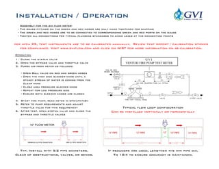
- 1. Typ. Install with 5/2 pipe diameters. Clear of obstructions, valves, or bends. If reducers are used, lengthen the min pipe dia. To 10/4 to ensure accuracy is maintained. Installation / Operation 1. Close the system valve 2. Open the by-pass valve and throttle valve 3. Purge air from meter as follows: - Open Ball valve on red and green hoses - Open the high side bleeder knob until a steady stream of water is coming from the Clear hose - Close high pressure bleeder knob - Repeat for low pressure side - Ensure both bleeder knobs are closed 4. Start fire pump, read meter in gpm/lpm/m3h 5. Refer to pump requirements and adjust throttle valve for this requirement 6. After test, open system valve and close the by-pass and throttle valves Typical flow loop configuration Can be installed vertically or horizontally Assembly for the gvi flow meter: - The brass fittings on the green and red hoses are only hand tightened for shipping - The green and red hoses are to be connected to corresponding green and red ports on the gauge - Tighten all connections per typical plumbing standards to avoid leaks at the connection points per nfpa 25, test instruments are to be calibrated annually. Review test report / calibration sticker for compliance. Visit www.gviflow.com and click on NIST for more information on re-calibration. Operation