Bridging the Worlds of 2D and 3D CAD Design
•
1 recomendación•1,528 vistas

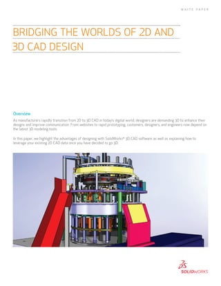
As manufacturers rapidly transition from 2D to 3D CAD in today’s digital world, designers are demanding 3D to enhance their designs and improve communication. From websites to rapid prototyping, customers, designers, and engineers now depend on the latest 3D modeling tools. In this paper, we highlight the advantages of designing with SolidWorks® 3D CAD software as well as explaining how to leverage your existing 2D CAD data once you have decided to go 3D.

Recomendados
Más contenido relacionado
La actualidad más candente
La actualidad más candente (19)
Destacado
Destacado (13)
Similar a Bridging the Worlds of 2D and 3D CAD Design
Similar a Bridging the Worlds of 2D and 3D CAD Design (20)
Más de SOLIDWORKS
Más de SOLIDWORKS (14)
Último
Último (20)
Bridging the Worlds of 2D and 3D CAD Design
- 1. Overview As manufacturers rapidly transition from 2D to 3D CAD in today’s digital world, designers are demanding 3D to enhance their designs and improve communication. From websites to rapid prototyping, customers, designers, and engineers now depend on the latest 3D modeling tools. In this paper, we highlight the advantages of designing with SolidWorks® 3D CAD software as well as explaining how to leverage your existing 2D CAD data once you have decided to go 3D. BRIDGING THE WORLDS OF 2D AND 3D CAD DESIGN W H I T E P A P E R
- 2. Advantages of 3D CAD As you work with 3D CAD software, you will quickly discover that 3D enhances not only the design process, but also communication with your customers and design team. Following are the main advantages of using SolidWorks 3D CAD software: Enhance visualization and communication CAD is all about communicating ideas. We live in a 3D world, so we visualize objects in the same way. When it comes to communicating a design, we naturally prefer a 3D image, model, or animation over a 2D technical drawing. In the 2D world, designers must be able to look at three or four views of a design and mentally combine them in order to visualize what that design will look like in 3D. By moving from 2D to SolidWorks 3D design, HSG discovered how improved visualization fosters collaboration and innovation. While engineers and drafters can understand a 2D drawing, your customers, salespeople, buyers, and suppliers may find it much more difficult to comprehend. Looking at a design in 3D versus 2D eliminates the need for viewers to have mastered this technical knowledge. With SolidWorks Professional software, Multiquip has improved efficiencies in virtually every downstream function in the product development process. Bridging the Worlds of 2D and 3D CAD Design 2
- 3. Bridging the Worlds of 2D and 3D CAD Design 3 Rick Morse, owner of Pearce Processing Systems in Gloucester, Massachusetts, says that being able to present his proposals and finished designs in 3D to his customers makes communication much easier than providing them 2D drawings. Morse also makes extensive use of 3D animation. The ability to show his customers a “movie” of the machine in action not only communicates how the machine will function, but also gives him an edge over others who are submitting 2D drawings in the quoting phase. With 3D images and 3D animations potential customers feel more confident in what Morse will be delivering as a finished product. Combine this with the ability to add photorealistic finishes to 3D models, and you can often find it difficult to tell if you are looking at a CAD model on a photograph of the actual physical machine. Vermeer uses SolidWorks software to check for interferences and collisions in large assembly designs, which range from 500 to 4,000 parts. In addition to presentation benefits, 3D assembly models can be quickly and easily “exploded” to create exploded views for technical illustrations and assembly instructions without requiring any further drafting. And when 2D drawings are needed for manufacturing, 3D CAD provides automatic view creation for any 2D view needed, including section views and detailed views. The ability to generate 3D images and animations also makes it easier to communicate with others besides customers. Sales, marketing, field service, operations staff, financial personnel, and management may also find it challenging to interpret a 2D drawing. Yet they will readily understand the design when presented in 3D where you can rotate, zoom, measure, animate, and even “walk through” your designs.
- 4. Bridging the Worlds of 2D and 3D CAD Design 4 3D CAD software allows you to thoroughly explore an assembly with explode, unexplode, and hide parts from views capabilities. Eliminate manual updates In 2D, you have to manually update every drawing view whenever a change occurs. Change one part and you not only have to include that change in each of the three drawing views for the part, you must also change every view of every assembly in which that part is used. Rick Morse says he wonders how they ever made a machine in the past in 2D CAD. He spent much of his design time just trying to keep all his drawing views up to date as his designs evolved. Morse relates that in designing complex food processing machines, his company incorporates many design changes for both machine function and manufacturing cost reasons. Because he had to manually control the coordination between hundreds of drawing views in 2D CAD, there were thousands of opportunities for mistakes. So, eliminating the need to interpret the design is one of the ways that working in 3D saves time. Consider how many views need to be updated manually in 2D each time a simple change is made to your design. A minor change to a dimension on a part triggers a series of updates. First consider the drawing of the part—all the views, usually at least three, must be modified. Then, drawings of the assemblies that contain that part—again, most likely three views, must be updated. And what happens if that part exists multiple times in an assembly? Also, how can you be sure you updated all the drawings in which that part is used? Luckily in SolidWorks software, you don’t have to worry about any of this. Enter the concept of associativity. In SolidWorks software, when you change a part model, such as the length of the part or hole diameter, or even add a new feature to a part, the change is automatically rippled through to every drawing view, every assembly, and anywhere else that part is used. And when you want to know what other files will be affected by the change, SolidWorks software also provides the ability to automatically track and identify where the part is used—what subassembly, what higher level assembly, and what drawings, so that you can make sure you are modifying only files and designs that you really want to modify.
- 5. Bridging the Worlds of 2D and 3D CAD Design 5 2D drawing views are automatically created from the 3D model and updated whenever the model is changed. Reduce errors with interference and collision checking On a 2D drawing, part interferences are difficult to find, especially when the design becomes large and complicated. In addition, because updates to 2D take so much time, many users often take shortcuts, like changing a dimension on a part without updating the actual size of the model. How many times have you heard that “the drawing is not to scale”? Add to this the fact that multiple designers will be sharing the assembly design duties, and the potential for interfering parts almost becomes a certainty. Checking 2D drawings to identify possible interference issues is extremely time-consuming, and interferences inevitably fall through the cracks, even with the most diligent checkers. In SolidWorks software, you can eliminate interference between parts. Interference checking is automatic, and every part can be checked to see if it interferes with any other part. Interference problems are highlighted, and even the amount of the interference is reported. With SolidWorks software you can also automate the process of hole alignment checking. Checking interference in an assembly that is static is difficult enough in 2D, but it becomes almost impossible when you are dealing with a design that moves, like a packaging machine, or a piece of automation equipment. There are virtually an infinite number of possibilities for a collision to occur in designs that move. In 2D there is really no practical way to check for a collision. Fortunately, SolidWorks software has a solution for collisions also. In SolidWorks software you can “move” your design through its full range of motion while continuously checking for collisions between parts. When a collision is detected, the motion will automatically stop, and the interference will be highlighted. SolidWorks software even provides an audible sound to let you know when parts interfere. If you make designs with internal moving components, Collision Detection is an invaluable tool to check the function of your design.
- 6. Bridging the Worlds of 2D and 3D CAD Design 6 Interferences also result from tolerancing problems. SolidWorks software provides the ability to automatically check maximum and minimum tolerance conditions with its TolAnalyst™ functionality, so you can ensure the tolerances you are applying to your parts are appropriate. It even identifies which tolerances are the largest contributors to the tolerance stack-up problem, thereby saving you time in trying to figure out which tolerances to tighten, or which dimensioning schemes to change. When fit and function errors go down, efficiency goes up, and you reduce time, labor, and material costs. SolidWorks software checks hole alignment automatically. Automatic Systems Inc. (ASI) in Kansas City, Missouri, manufactures a wide range of industrial material-handling equipment to move everything from coal to car bodies. Wayne Tiffany, senior machine designer, explains they often deal with large machine designs that require complicated material handling paths. He states that there is no reasonable way he can validate that his designs will fit together and function properly if he is using 2D. Catching and correcting interferences and collisions in 3D is invaluable. If these interference and collision problems were not picked up until final assembly and test, it could cost the company 10 or 100 times as much to fix the problem, and of course it would most likely impact delivery of the machine to the customer. Ultimately, says Tiffany, “SolidWorks software saves our company substantial money and time by catching problems before they go to manufacturing—these are problems that we had difficulty finding before in 2D.”
- 7. Bridging the Worlds of 2D and 3D CAD Design 7 Reuse existing designs Two unique aspects of SolidWorks software allow you to make easy and extensive reuse of existing designs: associativity and modifiability. As discussed earlier, “associativity” means when you change a design model, the change automatically ripples through to all the other places where that model is used—the drawings, higher level assemblies, and more. By “modifiability” we mean you can change a part by clicking and changing a dimension and all other geometry on that part resizes appropriately and automatically. For example, if you have modeled a five- inch-long plate with holes dimensioned one inch from either end, and then click on the five inch dimension and change it to 10 inches, the hole location would update, but the holes would still be one inch from either end of the part. As you can see from this example, SolidWorks software also allows you to capture your design intent, another very important aspect of designing in 3D. The design “intent” in this example is that you always want the holes to be one inch from the ends of the part no matter how long the part is. With SolidWorks software you can speed the creation of multiple configurations. Associativity and modifiability let you reuse existing designs to create new versions or configurations easily. You can readily create multiple new configurations of a single part by varying particular dimensions and features. As an example, you could make one socket head cap screw and then make every length and diameter variation from that one design just by changing dimensions. Likewise, you could make an entire catalog of screws from one part by also varying thread pitch, head type, and material as well as length and diameter. SolidWorks software provides 3D parts catalogs containing supplier-certified 3D models both in the software and online at www.3DContentCentral.com. ASI’s Tiffany notes that he makes extensive use of the online parts catalog in the design of his material-handling equipment.
- 8. Bridging the Worlds of 2D and 3D CAD Design 8 You can automate the creation of new designs with DriveWorksXpress. Accelerate development cycles with virtual testing and optimization Speeding up a design cycle depends on more factors than simply streamlining the initial part or assembly design. Another major benefit with 3D modeling is the insight it offers through virtual testing, analysis, and optimization, which take many forms. Tiffany appreciates that working in SolidWorks software allows him to apply motion to the parts of an assembly and quickly evaluate many different designs against operational requirements. Designers can assign a material type to a part and identify the mass properties, including weight and center of gravity. SolidWorks software provides an array of simulation and optimization tools to help you calculate forces due to motion, part stress, and deflection as well as vibration, flow, and effects of temperature.
- 9. Bridging the Worlds of 2D and 3D CAD Design 9 In addition the motion simulation capability found in SolidWorks software allows you to evaluate the effects of different motor performance curves, friction, springs, gravity, and other physical characteristics of a design. So rather than just running an animation of the machine in motion, you can simulate what really is happening in your design. The motion simulation automatically calculates forces on critical components, like bearings, bushings, and linkages. This information is then used to calculate part strengths, deflection, fatigue, and safety factors. Thermal, vibration, and flow analysis are also provided directly inside SolidWorks software so that your design can be optimized. In this way, SolidWorks software can be used to solve typical design problems, such as: How much weight can I remove from this part yet still have it function within a certain factor of safety? Will the part bend too much if it is made from a different material? In an electronic enclosure, will a specific component overheat from lack of airflow? Design for manufacturing Many of the new manufacturing technologies rely on the availability of a 3D CAD model as a starting point. For example, three-axis and up NC programming, rapid prototyping, mold design, and even sheet-metal manufacturing now require 3D models that can be referenced to create NC toolpaths, SLA models, and sheetmetal flat patterns with proper bend allowances. More and more companies are turning to rapid prototyping and manufacturing to reduce the turnaround time for both prototype parts and customized final parts, such as hearing aid shells. These rapid systems operate from 3D modeling input generated in standard template library (STL) format—a file format that you can output from your 3D CAD model by simply saving your model in that format. If a manufacturer has to “rebuild” your 2D design in 3D, two problems arise. First, the remodeling is adding an extra step to the manufacturing process, which takes extra time. Many shops that require 3D CAD models will put 2D jobs at the back of the queue because of the work required to convert your 2D design to 3D. To most manufacturers this is just additional prep work before getting to the manufacturing process. Manufacturers want their shops running at capacity, prep work costs them machining time, and they will charge you, the customer, for that time lost to prep. The second problem that arises is that the person making the 3D model can make a mistake in converting your 2D design to 3D; this means the part delivered to you may not meet your design requirements, which can ultimately affect the delivery of your product. By working in 3D from the start, you can generate files that are ready to go directly to manufacturing operations that require 3D CAD models. In many cases, 2D drawings are not even required for manufacturing. For example, SolidWorks software can output the 3D model complete with detailed dimensioning and tolerancing information as well as notes. In this way, all the data and notes needed to manufacture the part are included directly in the 3D CAD model. SolidWorks software’s DimXpert (dimensioning expert) automatically dimensions and tolerances the 3D model so that it is ready for manufacturing. The built-in intelligence of DimXpert allows users to automatically dimension models per the ASME Y14.5M-1994 standard for “Dimensioning and Tolerancing,” as well as display the dimensions in 3D per ASME Y14.41-2003, “Digital Product Definition Data Practices.” DimXpert even has a check to tell the designer when the model is fully dimensioned and toleranced and ready for the shop. Bottom line—3D parts and drawings go to the shop floor more correct and more complete, and machinists spend less time asking engineers and designers questions about incomplete manufacturing drawings, and more time machining.
- 10. Bridging the Worlds of 2D and 3D CAD Design 10 With SolidWorks software you can automatically dimension 3D models according to industry standards. With SolidWorks software, design-for-manufacturing (DFM) becomes more than a catch phrase. Built-in manufacturing intelligence (called DFMXpress) directs the software to check for features that are expensive or impossible to manufacture. These features are highlighted, and the user is provided an interactive list of the problems uncovered. Communication between manufacturing and engineering is also greatly improved through the use of 3D. There is a wide range of 3D digitizing and inspection equipment that also requires 3D CAD models. With the complete details at hand in the 3D CAD model, you can more easily verify molded, forged, stamped, and cast parts, including the details of undercuts, draft, thickness, and surface topology. With SolidWorks software, manufacturing is provided more useful and richer information—machinists can measure and section 3D parts live at the touch of a button. Assemblers and fabricators can explode assemblies, and zoom in and hide parts from view to see details they could never see before in 2D drawings. The benefits of improved communications possible with 3D images and exploded animations makes training a new employee or instructing a seasoned assembler easier. With DFMXpress you can review more closely the features of your designs that are costly and difficult to machine.
- 11. Bridging the Worlds of 2D and 3D CAD Design 11 Create bills of materials and manage data smoothly Working with an associative 3D CAD system also guarantees an accurate and current bill of materials (BOM). The BOM is always accurate because it automatically updates with changes you make to parts and assemblies. Data management is always critical to the product development process. Designs often go through several stages of development, such as concept, detailed engineering design, assembly and test, and final release to production. Controlling data is especially important when you consider all the personnel that are required to develop and manufacture a product: engineering, manufacturing, purchasing, sales, marketing, vendors, and even customers need to know that they are looking at the correct, most current data. Dassault Systèmes SolidWorks Corp. offers product data management software to control access to and revision tracking of design data—even if the design work is being done in multiple locations. SolidWorks product data management software ensures that the proper release procedures and approvals for your designs are executed from stage to stage. Sales and marketing tools Sales and marketing can also reap the benefits of 3D CAD data. Publication tools fully support the use of 3D CAD data to allow the creation of photorealistic 2D images, 3D models, and animations that appeal more to customers and consumers. Just look at any major automobile manufacturer’s website, and you will see the demand to present products in a more complete, colorful, and photorealistic way. Photorealistic models and animation capabilities as well as rapid prototyping also allow marketing to perform product market research at much lower costs than actually designing and producing prototypes in the conventional manner. Use 3D CAD models to more effectively communicate your designs on the web, in animations, and more.
- 12. Bridging the Worlds of 2D and 3D CAD Design 12 What to do with existing 2D CAD data So what happens to all the 2D CAD data that you have been developing for years when you decide to switch to 3D, and what do you do about all the customers that you need to communicate with in 2D? Let’s take a look at these questions in detail. Communicating with 2D users Even though you may be designing in 3D, SolidWorks software can output drawings and images in multiple 2D formats. In this way, you can still output documentation that is compatible with all the common 2D formats, such as DWG, DXF™, PDF, and JPEG. Converting 2D data to 3D In one sense, 3D design is really just an extension of what you are already doing in 2D. You start with a simple 2D sketch, which is similar to the cross-section of the 3D feature that you want to create. Then simply take that sketch and pull it out, revolve it, or drag (or sweep) it along a path. That is the basic technique to 3D geometry creation—just one more step beyond the sketching of the section. If existing 2D designs will be the basis for creating your next-generation products, it makes sense to take the time to remodel them in 3D. Besides supporting the export of data to several 2D formats, SolidWorks software supports the import of data in the DXF and DWG formats as well as AutoCAD® blocks, allowing the creation of 3D models directly from 2D data. SolidWorks software has unique tools for accelerating the design of 3D models including a tool called Design Clipart that allows you to drag and drop drawing views from DWG files into 3D SolidWorks software models, and another functionality called View Folding can help automate the creation of a 3D model by manipulating the views of an imported 2D drawing. Also, SolidWorks software supports the import of 2D “blocks” from AutoCAD as the basis for sketching a new 3D feature in SolidWorks software. In addition to using these helpful conversion tools, you can find contract services that specialize in the conversion of 2D drawings to 3D models.
- 13. SolidWorks is a registered trademark of Dassault Systèmes SolidWorks Corp. All other company and product names are trademarks or registered trademarks of their respective owners. ©2010 Dassault Systèmes. All rights reserved. MK3DCWPENG1210 Conclusion As outlined in this paper, 3D CAD design has many inherent benefits over working in 2D. Product visualization and presentation are improved, parts and drawing views update automatically and accurately, and interference and collision checking provides an automated, error-free way to check for interferences and collisions before manufacturing the product. In addition, 3D does not have to be an all-or- nothing process. You can keep existing designs in 2D, and then transition them as needed into the 3D system. However, two facts are clear: First, the world of design and manufacturing is definitely transitioning to 3D; and second, customers and designers are all demanding 3D to enhance design and communication. Organic shapes, so prevalent in the design of consumer products, from cars to cell phones, are much easier to model and manufacture in 3D. And with the tolerances expected from today’s consumer product and automotive designs, 2D sections are now unacceptable for defining these organic shapes because 2D does not provide enough surface control between sections. Fortunately, colleges, technical schools, and high schools are responding to the need for engineers and designers trained in 3D CAD. For more than 15 years, requests for 3D CAD training have been outpacing requests for 2D CAD training. This has resulted in a large pool of new and experienced designers and engineers familiar with 3D CAD, who can be found anywhere in the world. For your existing employees, training options are available in all forms, from book- to web-based to classroom training. You can pick the time, format, and length of training you want, and a course will be available to fit your schedule and budget. Finally, 3D modeling breathes new life into your current design process, attracts and retains designers and engineers eager to use the latest design tools, and even improves your company image to customers and vendors. It is a rare business today that can function productively without email and websites—3D design is another big step to operating fully in this increasingly digital world. Dassault Systèmes SolidWorks Corp. 300 Baker Avenue Concord, MA 01742 USA Phone: 1 800 693 9000 Outside the US: +1 978 371 5011 Email: info@solidworks.com www.solidworks.com