
Recomendados
Más contenido relacionado
Similar a Lecture-04 Piles.pptx
Similar a Lecture-04 Piles.pptx (20)
Último
Último (20)
Lecture-04 Piles.pptx
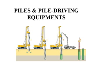
- 2. Piles can be classified on the basis of either their use or the materials from which they are made. On the Basis of use they are classified as: 1. Sheet Piles 2. Load Bearing Piles Sheet Piles are used primarily to retain or support Earth. Load Bearing Piles, as the name implies used primarily to transmit structural load.
- 3. IMPORTANT TERMS 1. ANCHOR PILES: A Pile connected to a structure by one or more ties to furnish lateral support or to resist uplift. 2. BUT OF A PILE: The larger end of a tapered pile, usually the upper end of a driven pile. 3. CUSHION: Material inserted between the ram of the pile hammer and the driving cap and for concrete piles also between the driving cap and pile. This material provides a uniform distribution of impact forces. 4. CUTOFF: The prescribed elevation at which the top of a driven pile is cut. Also the portion of pile removed from the upper end of the pile after driving
- 4. 5. DOWN DRAG: Negative friction of soil gripping a pile in the case of settling soils. This condition adds load to the installed pile. 6. DRIVING CAP OR HELMET: A steel cap placed over the pile butt to prevent damage to the pile during driving. It is formed to accept a specific- shaped pile, along with its cushion, if used. 7. OVERDRIVING: Driving a pile in a manner that damages the pile material. 8. PENETRATION: Gross penetration is the downward axial movement of the pile hammer blow. Net penetration is the gross penetration less the rebound, that is, the net downward movement of the pile per hammer blow. 9. PILE BENT: Two or more group driven in the group and fastened together by a cap or bracing. 10. PILE DRIVING SHOE: A metal shoe placed on the pile tip to prevent damage to the pile and to improve driving penetration.
- 5. 11. PILE TIP: The lower and in the case of timber piles usually the smaller end of a pile. 12. SOLDIER PILE: An H or wide-flange (WF) member driven at intervals of a few feet into which horizontal lagging is placed to support the walls of an excavation. 13. TENSION PILE: A Pile designed to resist uplift.
- 6. LOAD BEARING PILES Load Bearing pile can be classified as: 1. Timber Piles 2. Concrete Piles 3. Steel Piles 4. Composite Piles
- 7. CONCRETE PILES Concrete piles may be either Precast or Cast-in-Place. Mostly precast piles are manufactured in established plants and are either pre-stressed or post tensioned. Cast in Place piles are cast on the job site and are classified as cased. Cased types of piles are formed by either driving a hollow steel tube, with a closed end, into the ground or by drilling and then placing the casing, and then filling the casing with concrete. The uncased type is formed by first driving a casing to the required depth. The casing is filled with concrete and then removed, leaving the concrete in contact with the earth.
- 8. PRECAST-PRESTRESSED PILES Piles after casting, are normally steam cured until they have reached sufficient strength to allow them to be removed from the forms. Pre-stressed concrete piles are reinforced with either 0.5in or 7 16 𝑖𝑛 270 Ksi high strength stress-relieved or low relaxation tendons or strands. Piles are reinforced by spiral reinforcement. The amount of reinforcing placed at the ends of the pile increases to resist cracking and spalling during driving.
- 9. DRIVING CONCRETE PILES Any driven pile must remain structurally intact and not be stressed to its structural limits either during its service life or during driving. In most cases, the highest stress level occur in a pile during driving. Pile damage often occurs because of excessive stress levels generated during driving. Control of driving stress is a critical pile driving requirements.
- 10. PRECAUTIONS OF EXCESSIVE STRESS 1. Adequate cushioning material between the pile driver’s driving cap and the top of the concrete pile is a very economical way of reducing driving stress in the pile. 2. Driving stresses are proportional to the ram impact velocity, therefore stresses are reduced by using a hammer with a heavy ram and a low impact velocity or large stroke. 3. Care must be taken when driving piles through soils layers with low resistance. If such soils are anticipated or encountered, it is important to reduce the ram velocity or stroke of the hammer to avoid critical tensile stresses in the pile.
- 11. 4. In the case of cylinder piles, it is important to prevent the soil plug inside the pile from rising to an elevation above the level of the existing soil on the outside of the pile, thus creating unequal stresses in the pile. 5. The driving cap should fit loosely around the top of the pile so that pile can rotate slightly without binding within the driving head. This will prevent the development of the torsional stresses. 6. The top of the pile must be square or perpendicular to the longitudinal axis of the pile to eliminate eccentricity that causes stress. 7. The ends of the pre-stressing strand or reinforcing must either be cut off flush with the top of the pile or the driving cap must be designed so that the reinforcing threads through the pile cap in order that the hammer’s ram does not directly contact the reinforcing during driving.
- 12. CAST IN PLACE CONCRETE PILES They are constructed by placing concrete into a tapered or cylindrical hole previously driven into the ground or into a hole in the ground from which a driven mandrel (Steel core) has been withdrawn. In both of the cases, the hole has been created by a driving process that displaced the ground. The cast-in-place displacement-type pile can be of two forms. The first one involves driving a temporary steel tube with a closed end into the ground to form a void in the soil, which is then filled with the concrete as the tube is withdrawn. The second type is the same except the steel tube is left in plac to form a permanent casing.
- 13. RESISTANCE OF PILE TO PENETRATION The forces that enable a pile to support a load also cause the pile to resist the efforts made to drive it. The total resistance of a pile to penetration will equal the sum of the forces produced by skin friction and end bearing. The relative portions of the resistance contributed by either skin friction or end bearing may vary from 0% to 100% depending more on soil type than on the type of pile. The value of skin friction is a function of the coefficient of friction between the pile and the soil and the pressure of the soil normal to the surface of the pile.
- 14. Q. Consider a concrete pile driven into a soil that produces a normal pressure of 100psi on the vertical surface of the pile. If the co-efficient of friction is 0.25, the value of skin friction will be : = 0.25 x 100psi =25Psi =25 x 144Psf =3600Psf
- 15. HAMMER SELECTION For selecting a suitable hammer for any project several factors need to be considered: 1. Size and type of Piles. 2. The number of Piles 3. The character of the soil. 4. The location of the project. 5. The topography of the project. 6. The type of rig (crane) available 7. Condition of driving on Earth or on Water.
- 16. Estimation of Pile Bearing Capacity Following is the equation used to measure bearing capacity of any pile: R= 2𝑊𝐻 𝑆+0.1 Where, R= Safe load on a pile in lbs W= Weight of a falling mass in lbs H= Height of free fall for mass W in feet. S= Avg. penetration per blow for last 5 or 10 blows in inches.
- 17. TOPICS TO BE COVERED FROM HAND OUTS: Types of Hammers Process of installing Precast concrete Piles. Process of installing Cast-in-Place concrete piles. Steel Piles with types. Composite Piles.