3. ETSI
ETSI TS 132 407 V12.0.0 (2014-10)33GPP TS 32.407 version 12.0.0 Release 12
Intellectual Property Rights
IPRs essential or potentially essential to the present document may have been declared to ETSI. The information
pertaining to these essential IPRs, if any, is publicly available for ETSI members and non-members, and can be found
in ETSI SR 000 314: "Intellectual Property Rights (IPRs); Essential, or potentially Essential, IPRs notified to ETSI in
respect of ETSI standards", which is available from the ETSI Secretariat. Latest updates are available on the ETSI Web
server (http://ipr.etsi.org).
Pursuant to the ETSI IPR Policy, no investigation, including IPR searches, has been carried out by ETSI. No guarantee
can be given as to the existence of other IPRs not referenced in ETSI SR 000 314 (or the updates on the ETSI Web
server) which are, or may be, or may become, essential to the present document.
Foreword
This Technical Specification (TS) has been produced by ETSI 3rd Generation Partnership Project (3GPP).
The present document may refer to technical specifications or reports using their 3GPP identities, UMTS identities or
GSM identities. These should be interpreted as being references to the corresponding ETSI deliverables.
The cross reference between GSM, UMTS, 3GPP and ETSI identities can be found under
http://webapp.etsi.org/key/queryform.asp.
Modal verbs terminology
In the present document "shall", "shall not", "should", "should not", "may", "may not", "need", "need not", "will",
"will not", "can" and "cannot" are to be interpreted as described in clause 3.2 of the ETSI Drafting Rules (Verbal forms
for the expression of provisions).
"must" and "must not" are NOT allowed in ETSI deliverables except when used in direct citation.
4. ETSI
ETSI TS 132 407 V12.0.0 (2014-10)43GPP TS 32.407 version 12.0.0 Release 12
Contents
Intellectual Property Rights................................................................................................................................3
Foreword.............................................................................................................................................................3
Modal verbs terminology....................................................................................................................................3
Foreword...........................................................................................................................................................10
1 Scope......................................................................................................................................................12
2 References..............................................................................................................................................12
3 Measurement family and abbreviations..................................................................................................14
3.1 Measurements...................................................................................................................................................14
3.2 Abbreviations ...................................................................................................................................................14
4 Measurements related to the MSC Server..............................................................................................16
4.1 Call control management..................................................................................................................................16
4.1.1 Overview ....................................................................................................................................................16
4.1.1.1 Basic traffic model................................................................................................................................16
4.1.1.2 Basic signalling flow.............................................................................................................................17
4.1.2 MO/MT call related performance ...............................................................................................................18
4.1.2.1 MSC-S acknowledged originating calls................................................................................................19
4.1.2.2 MSC-S acknowledged terminating calls ...............................................................................................20
4.1.2.3 Attempted mobile originating calls.......................................................................................................20
4.1.2.4 Successful mobile originating call ........................................................................................................20
4.1.2.5 Answered mobile originating calls........................................................................................................21
4.1.2.6 Attempted mobile terminating calls ......................................................................................................21
4.1.2.7 Successful mobile terminating calls......................................................................................................22
4.1.2.8 Answered mobile terminating calls.......................................................................................................22
4.1.2.9 Failed mobile calls caused by subscribers in originating MSC-S for Inter-MSC call...........................23
4.1.2.10 Failed mobile calls caused by subscribers in terminating MSC-S for Inter-MSC call..........................24
4.1.2.11 Failed mobile calls caused by subscribers in MSC-S for Intra-MSC call .............................................25
4.1.3 MSC-S (BICC) call related performance....................................................................................................26
4.1.3.1 Attempted incoming calls .....................................................................................................................26
4.1.3.2 Successful incoming calls .....................................................................................................................27
4.1.3.3 Answered incoming calls ......................................................................................................................27
4.1.3.4 Attempted outgoing calls ......................................................................................................................27
4.1.3.5 Successful outgoing calls ......................................................................................................................28
4.1.3.6 Answered outgoing calls.......................................................................................................................28
4.1.4 Trunk group (TDM) call related performance ............................................................................................29
4.1.4.1 Seized outgoing calls per trunk group...................................................................................................29
4.1.4.2 Successful outgoing calls per trunk group ............................................................................................29
4.1.4.3 Answered outgoing calls per trunk group .............................................................................................29
4.1.4.4 Number of trunk group overflow ..........................................................................................................30
4.1.4.5 Seized incoming calls per trunk group..................................................................................................30
4.1.4.6 Time of all trunks unavailable...............................................................................................................30
4.1.4.7 Successful incoming calls per trunk group............................................................................................30
4.1.4.8 Answered incoming call per trunk group..............................................................................................31
4.1.5 Call establishment quality of service ..........................................................................................................32
4.1.5.1 UE call established time........................................................................................................................32
4.1.6 Traffic related performance ........................................................................................................................32
4.1.6.1 Successful incoming call traffic............................................................................................................32
4.1.6.2 Answered incoming call traffic.............................................................................................................33
4.1.6.3 Successful mobile originating call traffic..............................................................................................33
4.1.6.4 Answered mobile originating call traffic...............................................................................................34
4.1.6.5 Successful Mobile terminating call traffic ............................................................................................34
4.1.6.6 Answered Mobile terminating call traffic .............................................................................................35
4.1.6.7 Successful outgoing traffic....................................................................................................................35
4.1.6.8 Answered outgoing traffic.....................................................................................................................37
5. ETSI
ETSI TS 132 407 V12.0.0 (2014-10)53GPP TS 32.407 version 12.0.0 Release 12
4.1.6.9 Successful transit call traffic .................................................................................................................37
4.1.6.10 Answered transit call traffic..................................................................................................................38
4.1.6.11 Seized outgoing call traffic per trunk group..........................................................................................38
4.1.6.12 Seized incoming call traffic per trunk group.........................................................................................39
4.1.7 Paging related performance ........................................................................................................................40
4.1.7.1 Attempt paging requests per Lac...........................................................................................................40
4.1.7.2 Successful paging requests per Lac.......................................................................................................41
4.1.8 Out of band Call codec negotiation related performance............................................................................42
4.1.8.1 Attempted out of band codec negotiation number ................................................................................42
4.1.8.2 Successful out of band codec negotiation number ................................................................................43
4.1.8.3 Attempted out of band codec modification number..............................................................................43
4.1.8.4 Successful out of band codec modification number..............................................................................43
4.1.8.5 Failed out of band codec modification number.....................................................................................44
4.1.9 Measurements based on Observed Destination...........................................................................................45
4.1.9.1 Attempted calls for calling party number..............................................................................................45
4.1.9.2 Successful calls for calling party number..............................................................................................45
4.1.9.3 Answered calls for calling party number ..............................................................................................46
4.1.9.4 Call Traffic of Observed Destination for calling party number ............................................................46
4.1.9.5 Attempted calls for called party numbers..............................................................................................46
4.1.9.6 Successful calls for the called party numbers........................................................................................47
4.1.9.7 Answered calls for the called party numbers ........................................................................................47
4.1.9.8 Call Traffic of Observed Destination for called party number..............................................................47
4.2 Mobility management.......................................................................................................................................48
4.2.1 Overview ....................................................................................................................................................48
4.2.2 Location update ..........................................................................................................................................49
4.2.2.1 Attempted intra-VLR location update...................................................................................................49
4.2.2.2 Successful intra-VLR location update...................................................................................................49
4.2.2.3 Attempted inter-VLR location update...................................................................................................50
4.2.2.4 Successful inter-VLR location update...................................................................................................50
4.2.2.5 Attempted location update for IMSI attach...........................................................................................51
4.2.2.6 Successful location update for IMSI attach...........................................................................................51
4.2.2.7 Attempted period location update .........................................................................................................52
4.2.2.8 Successful period location update.........................................................................................................52
4.2.3 Hand over inter MSC-S ..............................................................................................................................53
4.2.3.1 Attempted subsequent handover back to MSCa....................................................................................53
4.2.3.2 Successful subsequent handover back to MSCa ...................................................................................54
4.2.3.3 Attempted subsequent handover to MSCc ............................................................................................54
4.2.3.4 Successful subsequent handover to MSCc............................................................................................54
4.2.3.5 Attempted incoming handovers inter MSC-S from UMTS to UMTS ..................................................55
4.2.3.6 Successful incoming handovers inter MSC-S from UMTS to UMTS ..................................................55
4.2.3.7 Attempted outgoing handovers inter MSC-S from UMTS to UMTS ...................................................55
4.2.3.8 Successful outgoing handovers inter MSC-S from UMTS to UMTS...................................................56
4.2.3.9 Attempted incoming handovers inter MSC-S from UMTS to GSM.....................................................56
4.2.3.10 Successful incoming handovers inter MSC-S from UMTS to GSM.....................................................56
4.2.3.11 Attempted outgoing handovers inter MSC-S from UMTS to GSM......................................................57
4.2.3.12 Successful outgoing handovers inter MSC-S from UMTS to GSM .....................................................57
4.2.4 Handover Intra MSC-S ...............................................................................................................................57
4.2.4.1 Attempted Handover Intra MSC-S from UMTS to GSM .....................................................................57
4.2.4.2 Successful Handover Intra MSC-S from UMTS to GSM.....................................................................58
4.2.4.3 Failed Handover Intra MSC-S from UMTS to GSM ............................................................................58
4.2.4.4 Attempted Handover Intra MSC-S from GSM to UMTS .....................................................................58
4.2.4.5 Successful Handover Intra MSC-S from GSM to UMTS.....................................................................58
4.2.4.6 Failed Handover Intra MSC-S from GSM to UMTS ............................................................................59
4.2.4.7 Attempted SRNS Relocation Intra MSC-S from UMTS to UMTS ......................................................59
4.2.4.8 Successful SRNS Relocation Intra MSC-S from UMTS to UMTS ......................................................59
4.2.4.9 Failed SRNS Relocation Intra MSC-S from UMTS to UMTS .............................................................60
4.3 Signalling .........................................................................................................................................................61
4.3.1 Overview ....................................................................................................................................................61
4.3.2 M3UA link related measurements ..............................................................................................................61
4.3.2.1 Number of received messages on M3UA link ......................................................................................61
4.3.2.2 Number of sent messages on M3UA link .............................................................................................61
4.3.2.3 Number of octets received on M3UA link............................................................................................61
6. ETSI
ETSI TS 132 407 V12.0.0 (2014-10)63GPP TS 32.407 version 12.0.0 Release 12
4.3.2.4 Number of octets sent on M3UA link ...................................................................................................62
4.3.2.5 Mean duration of M3UA link congestion .............................................................................................62
4.3.2.6 Number of M3UA link congestion times..............................................................................................62
4.3.2.7 Mean unavailable time of M3UA link ..................................................................................................63
4.3.2.8 Number of M3UA link unavailable times.............................................................................................63
4.3.3 MTP3 signalling link related measurements...............................................................................................63
4.3.3.1 Mean duration of unavailable MTP3 signalling link.............................................................................63
4.3.3.2 Number of MTP3 signalling link unavailable times .............................................................................64
4.3.3.3 Number of MSUs received on MTP3 signalling link............................................................................64
4.3.3.4 Number of MSUs sent on MTP3 signalling link...................................................................................64
4.3.3.5 Number of octets received on MTP3 signalling link.............................................................................65
4.3.3.6 Number of octets sent on MTP3 signalling link....................................................................................65
4.3.3.7 Number of available MTP3 signalling link...........................................................................................65
4.4 Equipment resource..........................................................................................................................................66
4.4.1 Overview ....................................................................................................................................................66
4.4.2 CPU Load ...................................................................................................................................................66
4.4.2.1 Mean CPU Usage..................................................................................................................................66
4.4.3 Number of subscribers in VLR...................................................................................................................66
4.4.3.1 Number of registered subscribers in VLR.............................................................................................66
4.4.3.2 Number of attached subscribers in VLR ...............................................................................................67
4.4.3.3 Number of registered national roaming subscribers in VLR.................................................................67
4.4.3.4 Number of attached national roaming subscribers in VLR..................................................................67
4.4.3.5 Number of registered international roaming subscriber in VLR...........................................................68
4.4.3.6 Number of attached international roaming subscribers in VLR............................................................68
4.4.4 Octets in MAC layer in MSC-S physical port ............................................................................................68
4.4.4.1 Number of octets sent on MAC layer in MSC-S physical port.............................................................68
4.4.4.2 Number of octets received on MAC layer in MSC-S physical port......................................................69
4.4.5 Trunk resource related measurements.........................................................................................................69
4.4.5.1 Number of available trunks...................................................................................................................69
4.4.5.2 Number of available circuits in trunk group .........................................................................................69
4.4.6 H.248 message related measurements on Mc interface ..............................................................................70
4.4.6.1 Number of H.248 messages received on Mc interface..........................................................................70
4.4.6.2 Number of H.248 messages sent on Mc interface.................................................................................70
4.4.6.3 Number of H.248 message octets received on Mc interface .................................................................70
4.4.6.4 Number of H.248 message octets sent on Mc interface ........................................................................71
4.4.7 BICC message on Nc interface related measurements................................................................................71
4.4.7.1 Number of BICC messages received on Nc interface...........................................................................71
4.4.7.2 Number of BICC messages sent on Nc interface ..................................................................................71
4.4.7.3 Number of octets of BICC message received on Nc interface..............................................................72
4.4.7.4 Number of octets of BICC message sent on Nc interface .....................................................................72
5 Measurements related to the CS MGW..................................................................................................73
5.1 Measurements related to signalling..................................................................................................................73
5.1.1 Overview ....................................................................................................................................................73
5.1.2 M3UA link of MGW related performance .................................................................................................73
5.1.2.1 Number of messages received on M3UA link ......................................................................................73
5.1.2.2 Number of messages sent on M3UA link .............................................................................................73
5.1.2.3 Number of octets received on M3UA link............................................................................................74
5.1.2.4 Number of octets sent on M3UA link ...................................................................................................74
5.1.2.5 Mean duration of M3UA link congestion .............................................................................................74
5.1.2.6 Number of M3UA link congestion times..............................................................................................75
5.1.2.7 Mean unavailable duration of M3UA link ............................................................................................75
5.1.2.8 Number of M3UA link unavailable times.............................................................................................75
5.1.3 MTP3/MTP3B signalling link of MGW related performance....................................................................76
5.1.3.1 Number of MSUs received on MTP3/MTP3B signalling link..............................................................76
5.1.3.2 Number of MSUs sent on MTP3/MTP3B signalling link.....................................................................76
5.1.3.3 Number of octets received on MTP3/MTP3B signalling link...............................................................76
5.1.3.4 Number of octets sent on MTP3/MTP3B signalling link......................................................................77
5.1.3.5 Number of available MTP3/MTP3B signalling link.............................................................................77
5.1.3.6 Number of unavailable times of MTP3/MTP3B signalling link ...........................................................77
5.1.3.7 Mean duration of unavailable MTP3/MTP3B signalling link...............................................................78
5.1.4 Route set related performance ....................................................................................................................78
7. ETSI
ETSI TS 132 407 V12.0.0 (2014-10)73GPP TS 32.407 version 12.0.0 Release 12
5.1.4.1 Number of occurrences of unavailability of a route set to a given destination .....................................78
5.1.4.2 Duration of unavailability of a route set to a given destination.............................................................78
5.2 Measurements related to bearer control............................................................................................................79
5.2.1 Overview ....................................................................................................................................................79
5.2.2 Measurements related to the ATM AAL2 connection setup.......................................................................79
5.2.2.1 Attempted AAL2 connection setup.......................................................................................................79
5.2.2.2 Successful AAL2 connection setup.......................................................................................................79
5.2.3 Measurements related to IP RTP connection..............................................................................................80
5.2.3.1 Attempted outgoing connection setup...................................................................................................80
5.2.3.2 Successful outgoing connection setup...................................................................................................80
5.2.3.3 Attempted incoming connection setup..................................................................................................80
5.2.3.4 Successful incoming connection setup..................................................................................................81
5.2.4 Measurements related to the User Plane (UP) Init......................................................................................81
5.2.4.1 Attempted outgoing initial UP on the Nb interface...............................................................................81
5.2.4.2 Successful outgoing initial UP on the Nb interface...............................................................................81
5.2.4.3 Attempted incoming initial UP on the Nb interface..............................................................................82
5.2.4.4 Successful incoming initial UP on the Nb interface..............................................................................82
5.2.4.5 Attempted outgoing initial UP on the Iu interface ................................................................................82
5.2.4.6 Successful outgoing initial UP on the Iu interface ................................................................................83
5.2.4.7 Attempted incoming initial UP on the Iu interface ...............................................................................83
5.2.4.8 Successful incoming initial UP on the Iu interface ...............................................................................83
5.3 Bearer transport................................................................................................................................................84
5.3.1 Overview ....................................................................................................................................................84
5.3.2 Measurements related to Nb interface ........................................................................................................84
5.3.2.1 Number of RTP messages received on Nb interface.............................................................................84
5.3.2.2 Number of RTP messages sent on Nb interface....................................................................................84
5.3.2.3 Number of RTP octets received on Nb interface...................................................................................84
5.3.2.4 Number of RTP octets sent on Nb interface..........................................................................................85
5.3.2.5 Number of lost RTP messages on Nb interface.....................................................................................85
5.3.2.6 The maximum delay on Nb interface....................................................................................................85
5.3.2.7 The maximum delay jitter on Nb interface ...........................................................................................86
5.3.2.8 The mean delay on Nb interface ...........................................................................................................86
5.3.2.9 The mean delay Jitter on Nb interface...................................................................................................86
5.3.3 AAL2 related measurements on Iu CS interface.........................................................................................87
5.3.3.1 Number of AAL2 packets received on IuCS interface..........................................................................87
5.3.3.2 Number of AAL2 packets sent on IuCS interface.................................................................................87
5.3.3.3 Octets of AAL2 packets received on IuCS interface.............................................................................87
5.3.3.4 Octets of AAL2 packets sent on IuCS interface....................................................................................87
5.3.4 RTP related measurements on Iu CS interface ...........................................................................................88
5.3.4.1 Number of RTP messages received on Iu interface ..............................................................................88
5.3.4.2 Number of RTP messages sent on Iu interface .....................................................................................89
5.3.4.3 Number of RTP octets received on Iu interface ....................................................................................89
5.3.4.4 Number of RTP octets sent on Iu interface ...........................................................................................89
5.3.4.5 Number of lost RTP packets on Iu interface .........................................................................................90
5.3.4.6 The maximum delay on Iu interface......................................................................................................90
5.3.4.7 The maximum delay jitter on Iu interface.............................................................................................90
5.3.2.8 The mean delay on Nb interface ...........................................................................................................91
5.3.2.9 The mean delay Jitter on Nb interface...................................................................................................91
5.3.5 Number of seized PVC link on Iu CS interface ..........................................................................................91
5.4 Equipment resource..........................................................................................................................................92
5.4.1 Overview ....................................................................................................................................................92
5.4.2 CPU Load ...................................................................................................................................................92
5.4.2.1 Mean CPU usage...................................................................................................................................92
5.4.3 Octets in MAC layer in MGW port ............................................................................................................93
5.4.3.1 Number of octets sent on MAC layer in MGW port.............................................................................93
5.4.3.2 Number of octets received on MAC layer in MGW port......................................................................93
5.4.4 H.248 message related measurements on Mc interface ..............................................................................94
5.4.4.1 Number of H.248 message received on Mc interface ...........................................................................94
5.4.4.2 Number of H.248 message sent on Mc interface ..................................................................................94
5.4.4.3 Number of H.248 message octets received on Mc interface .................................................................94
5.4.4.4 Number of H.248 message octets sent on Mc interface ........................................................................95
5.4.5 Transcode....................................................................................................................................................95
8. ETSI
ETSI TS 132 407 V12.0.0 (2014-10)83GPP TS 32.407 version 12.0.0 Release 12
5.4.5.1 Number of failed calls caused by transcode resource ...........................................................................95
5.4.5.2 Number of attempted seized transcoder................................................................................................95
5.5 User Plane services...........................................................................................................................................96
5.5.1 Overview ....................................................................................................................................................96
5.5.2 Continuity Check (CC) ...............................................................................................................................96
5.5.2.1 Number of seizure attempts for CC.......................................................................................................96
5.5.2.2 Number of successful CC seizures........................................................................................................96
5.5.3 DTMF Sending and Detection (DTMF) .....................................................................................................97
5.5.3.1 Number of seizure attempts for DTMF.................................................................................................97
5.5.3.2 Number of successful DTMF seizures ..................................................................................................97
5.5.4 Global Text Telephony (GTT)....................................................................................................................97
5.5.4.1 Number of seizure attempts for GTT ....................................................................................................97
5.5.4.2 Number of successful GTT seizures .....................................................................................................98
5.5.5 Media Frame Handler (MFH).....................................................................................................................98
5.5.5.1 Number of seizure attempts for MFH ...................................................................................................98
5.5.5.2 Number of successful MFH seizures.....................................................................................................98
5.5.6 Multiparty Call (MPC)................................................................................................................................99
5.5.6.1 Number of seizure attempts for MPC ...................................................................................................99
5.5.6.2 Number of successful MPC seizures.....................................................................................................99
5.5.7 Speech Coder (SC)......................................................................................................................................99
5.5.7.1 Number of seizure attempts for SC.......................................................................................................99
5.5.7.2 Number of successful SC seizures ......................................................................................................100
5.5.8 Tone Sender or Line Test (TS) .................................................................................................................100
5.5.8.1 Number of seizure attempts for TS .....................................................................................................100
5.5.8.2 Number of successful TS seizures ......................................................................................................100
6 Measurements related to the HLR........................................................................................................101
6.1 Equipment resource........................................................................................................................................101
6.1.1 Overview ..................................................................................................................................................101
6.1.2 CPU LOAD ..............................................................................................................................................101
6.1.2.1 Mean CPU usage.................................................................................................................................101
6.1.3 Subscribers related measurements ............................................................................................................102
6.1.3.1 Subscribers in HLR.............................................................................................................................102
6.1.4 MTP3 signalling link related measurements.............................................................................................103
6.1.4.1 Number of unavailable times of MTP3 signalling link.......................................................................103
6.1.4.2 Number of MSUs received on MTP3 signalling link..........................................................................103
6.1.4.3 Number of MSUs sent on MTP3 signalling link.................................................................................103
6.1.4.4 Number of octets received on MTP3 signalling link...........................................................................104
6.1.4.5 Number of octets sent on MTP3 signalling link..................................................................................104
6.1.4.6 Number of available MTP3 signalling link.........................................................................................104
6.1.4.7 Mean duration of unavailable MTP3 signalling link...........................................................................105
Annex A (informative): Examples for "(n-1) out of n" approach............................................................106
A.1 Attempt/success/failure procedure measurements ...............................................................................106
A.2 GSM/UMTS combined measurements.................................................................................................106
See 3GPP TS 32.404 bedded "(n-1) out of n" approaches .............................................................................106
Annex B (informative): Top-Down Performance Measurement Definition Process..............................107
Annex C (normative): Use cases for performance measurements defintion..........................................108
C.1 Use case of the Mean delay Jitter on Nb interface related measurements ...........................................108
C.2 Use case of the Mean delay Jitter on Nb interface related measurements ...........................................108
C.3 Use case of number of subscribers in VLR..........................................................................................108
C.4 Use case of Number of Handover Intra MSC-S...................................................................................108
Annex E (informative): Use case for measurements..................................................................................109
E.1 Use case for Iucslink and Alink related MO/MT and traffic measurements........................................109
9. ETSI
ETSI TS 132 407 V12.0.0 (2014-10)93GPP TS 32.407 version 12.0.0 Release 12
Annex E (informative): Change history .....................................................................................................110
History............................................................................................................................................................111
10. ETSI
ETSI TS 132 407 V12.0.0 (2014-10)103GPP TS 32.407 version 12.0.0 Release 12
Foreword
This Technical Specification has been produced by the 3rd
Generation Partnership Project (3GPP).
The contents of the present document are subject to continuing work within the TSG and may change following formal
TSG approval. Should the TSG modify the contents of the present document, it will be re-released by the TSG with an
identifying change of release date and an increase in version number as follows:
Version x.y.z
where:
x the first digit:
1 presented to TSG for information;
2 presented to TSG for approval;
3 or greater indicates TSG approved document under change control.
y the second digit is incremented for all changes of substance, i.e. technical enhancements, corrections,
updates, etc.
z the third digit is incremented when editorial only changes have been incorporated in the document.
Introduction
The present document is part of a TS-family covering the 3rd Generation Partnership Project; Technical Specification
Group Services and System Aspects; Telecommunication Management; as identified below:
TS 32.401 Performance Management (PM); Concept and requirements
TS 52.402 Performance Management (PM); Performance measurements - GSM
TS 32.404 Performance Management (PM); Performance measurements - Definitions and template
TS 32.405 Performance Management (PM); Performance measurements Universal Terrestrial Radio Access
Network (UTRAN)
TS 32.406 Performance Management (PM); Performance measurements Core Network (CN) Packet Switched
(PS) domain
TS 32.407 Performance Management (PM); Core Network (CN) Circuit Switched (CS) Domain;
Performance measurements - UMTS and combined UMTS/GSM
TS 32.408 Performance Management (PM); Performance measurements Teleservice
TS 32.409 Performance Management (PM); Performance measurements IP Multimedia Subsystem (IMS)
The present document is part of a set of specifications, which describe the requirements and information model
necessary for the standardised Operation, Administration and Maintenance (OA&M) of a multi-vendor 3G-system.
During the lifetime of a 3G network, its logical and physical configuration will undergo changes of varying degrees and
frequencies in order to optimise the utilisation of the network resources. These changes will be executed through
network configuration management activities and/or network engineering, see 3GPP TS 32.600 [3].
11. ETSI
ETSI TS 132 407 V12.0.0 (2014-10)113GPP TS 32.407 version 12.0.0 Release 12
Many of the activities involved in the daily operation and future network planning of a 3G network require data on
which to base decisions. This data refers to the load carried by the network and the grade of service offered. In order to
produce this data performance measurements are executed in the NEs, which comprise the network. The data can then
be transferred to an external system, e.g. an Operations System (OS) in TMN terminology, for further evaluation.
The purpose of the present document is to describe the mechanisms involved in the collection of the data and the
definition of the data itself.
For Measurement definition template and Management of per cause measurements see 3GPP TS 32.404 [8].
Annexes A and B of 3GPP TS 32.404 [8] also apply to the present document.
12. ETSI
ETSI TS 132 407 V12.0.0 (2014-10)123GPP TS 32.407 version 12.0.0 Release 12
1 Scope
The present document describes the CN CS measurements for UMTS and combined UMTS/GSM.
3GPP TS 32.401 [2] describes Performance Management concepts and requirements.
The present document is valid for all measurement types provided by an implementation of a UMTS network and
combined UMTS/GSM network. These may be measurement types defined within the present document, measurements
defined within other standards bodies, or vendor specific measurement types.
Only measurement types that are specific to CN CS UMTS or combined UMTS/GSM networks are defined within the
present documents. I.e. vendor specific measurement types used in UMTS and combined UMTS/GSM networks. Some
ATM or IP measurements defined here are only used for load carrying. The definition of the standard measurements is
intended to result in comparability of measurement data produced in a multi-vendor network, for those measurement
types that can be standardised across all vendors' implementations.
The structure of the present document is as follows:
- Header 1: Network Element (e.g. MSCServer related measurements);
- Header 2: Measurement function (e.g. handover measurements);
- Header 3: Measurements.
2 References
The following documents contain provisions which, through reference in this text, constitute provisions of the present
document.
• References are either specific (identified by date of publication and/or edition number or version number) or
non-specific.
• For a specific reference, subsequent revisions do not apply.
• For a non-specific reference, the latest version applies. In the case of a reference to a 3GPP document (including
a GSM document), a non-specific reference implicitly refers to the latest version of that document in the same
Release as the present document.
[1] ITU-T Recommendation Q.2630: "AAL type 2 signalling protocol".
[2] 3GPP TS 32.401: "Telecommunication management; Performance Management (PM); Concept
and requirements".
[3] 3GPP TS 32.600: "Telecommunication management; Configuration Management (CM); Concept
and high-level requirements".
[4] 3GPP TS 23.153: "Out of band transcoder control; Stage 2".
[5] 3GPP TS 25.413: "UTRAN Iu interface Radio Access Network Application Part (RANAP)
signalling".
[6] ITU-T Recommendation Q.1902: "Bearer Independent Call Control protocol (Capability Set 2)".
[7] ITU-T Recommendation Q.752: "Monitoring and measurements for Signalling System No. 7
networks".
[8] 3GPP TS 32.404 "Performance Management (PM); Performance measurements - Definitions and
template".
[9] 3GPP TS 32.622: "Telecommunication management; Configuration Management (CM); Generic
network resources Integration Reference Point (IRP): Network Resource Model (NRM)".
13. ETSI
ETSI TS 132 407 V12.0.0 (2014-10)133GPP TS 32.407 version 12.0.0 Release 12
[10] ITU-T Recommendation Q.723: "Telephone user part formats and codes".
[11] 3GPP TS 23.018: "Basic call handling Technical Realization".
[12] 3GPP TS 24.011: "Point-to-Point (PP) Short Message Service (SMS) support on Mobile Radio
Interface".
[13] 3GPP TS 52.402: "Telecommunication management; Performance Management (PM);
Performance measurements - GSM".
[14] 3GPP TS 24.008: "Mobile radio interface Layer 3 specification; Core network protocols; Stage 3".
[15] GSM 04.08: "Digital cellular telecommunications system (Phase 2); Mobile radio interface;
Layer 3 specification".
[16] ITU-T Recommendation Q.763: "Signalling System No. 7 - ISDN User Part formats and codes".
[17] 3GPP TS 09.02: "Mobile Application Part (MAP) Specification".
[18] 3GPP TS 23.008: "Organization of subscriber data".
[19] IETF RFC 2960: "Stream Control Transmission Protocol" at ftp://ftp.rfc-editor.org/in-
notes/rfc2960.txt
[20] 3GPP TS 32.742: "Telecommunication management; Configuration Management (CM);
Signalling Transport Network (STN) interface Network Resource Model (NRM) Integration
Reference Point (IRP): Information Service (IS)".
[21] IETF RFC 1889: "RTP: A Transport Protocol for Real-Time Applications" at ftp://ftp.rfc-
editor.org/in-notes/rfc1889.txt, Obsoleted by RFC 3550
[22] IETF RFC 3550: "RTP: A Transport Protocol for Real-Time Applications" at ftp://ftp.rfc-
editor.org/in-notes/rfc3550.txt
[23] ITU-T Recommendation Q.753: "Signalling System No. 7 management functions MRVT, SRVT
and CVT and definition of the OMASE-user" at http://www.itu.int/rec/T-REC-Q.753/en
[24] ITU-T Recommendation Q.724: "Signalling System No. 7 - Telephone User parts, Signalling
procedures".
[25] 3GPP TS 23.014: "Support of Dual Tone Multi-Frequency signalling".
[26] 3GPP TS 22.226: "Global Text Telephony; Stage 1".
[27] ITU-T Recommendation E.182: "Application of tones and recorded announcements in telephone
services".
[28] 3GPP TS 25.415: "UTRAN Iu interface user plane protocols".
[29] 3GPP TS 29.415: "Core network Nb interface user plane protocols".
[30] ITU-T Recommendation I.254.1: "Multiparty supplementary services: Conference calling
(CONF)".
[31] 3GPP TS 23.153: "Out of band transcoder control; Stage 2".
[32] 3GPP TS 26.071: "Mandatory speech CODEC speech processing functions; AMR speech
CODEC; General description".
[33] 3GPP TS 26.090: "Mandatory speech CODEC speech processing functions; AMR speech
CODEC; Transcoding functions".
[34] 3GPP TS 23.009: "Handover procedures".
14. ETSI
ETSI TS 132 407 V12.0.0 (2014-10)143GPP TS 32.407 version 12.0.0 Release 12
3 Measurement family and abbreviations
3.1 Measurements
The measurement names defined in the present document are all beginning with a prefix containing the measurement
family name (MM attIntraVlrLU). This family name identifies all measurements which relate to a given functionality
and it may be used for measurement administration (see 3GPP TS 32.401 [2]).
The list of families currently used in the present document is as follows:
• CC (measurements related to Call control Management).
• MM (measurements related to Mobility Management).
• SIG (measurements related to Signalling).
• EQPT(measurements related to Equipment resource).
• BC (measurements related to bearer control).
• BRT (measurements related to bearer transport).
• SC(measurements related to service control).
3.2 Abbreviations
For the purposes of the present document, the following abbreviations apply:
CEG CircuitEndPointSubgroup
CN Core Network
EM (Network) Element Manager
MSC Mobile services Switching Centre
MSU Message Signal Unit
NE Network Element
NM Network Manager
OS Operations System (EM, NM)
OSI Open Systems Interconnection
PM Performance Management
PVC Permanent Virtual Connection
RNC Radio Network Controller
UMTS Universal Mobile Telecommunications System
UTRAN Universal Terrestrial Radio Access Network
You can find below a list of abbreviations used within the measurement types for field E of the measurement template
(see clause 3.3).
Acpt Accept
Att Attempt(s,ed)
Auth Authentication
Avail Available
Answ Answer(ed)
Call Call
Conn Connection
CS Circuit switched
Ctrl Controlled
Fail Fail(ed, ure)
HO Handover
Inc Incoming
Inter Inter
Intra Intra
LK link
15. ETSI
ETSI TS 132 407 V12.0.0 (2014-10)153GPP TS 32.407 version 12.0.0 Release 12
MM Mobility Management
Nat National
Netw Network
Nbr Number
Oct Octet(s)
Out Outgoing
Origi Originate(ing,ed)
Pkt Packet(s)
PS Packet switched
Req Request(s,ed)
Res Resource
Setup Setup
MSC-S MSC or MSC SERVER
Msg message
Sig Signalling
Subs Subscriber
Succ Success(es,ful)
Termi terminate(ed,ing)
UE User Equipment
UTRAN UTRAN
MSU Message signal unit(s)
Vlr VLR
16. ETSI
ETSI TS 132 407 V12.0.0 (2014-10)163GPP TS 32.407 version 12.0.0 Release 12
4 Measurements related to the MSC Server
4.1 Call control management
4.1.1 Overview
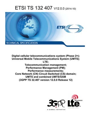
4.1.1.1 Basic traffic model
The call control management clause defines measurements related to the network call establishment, MO/MT call
control, inter MSC-S call control, etc. The traffic model using in this specification is depicted as follows.
SWITCH
E
G
H
BSC
RNC
other
exchange
BSC
RNC
other
exchange
A
B
C
D
F
M
N
O
P
A GSM Mobile Originating call
B WCDMA mobile originating call
C Incoming call
D Mobile originating call
E Internal call
F Terminating incoming call
G Originating outgoing call
H Transit call
M Mobile terminating call
N Outgoing call
O GSM mobile terminating call
P WCDMA mobile terminating call
Figure 1: Traffic model
In figure 1, D = A + B 、M = E + F. The D/M can be calculated from other measurements.
17. ETSI
ETSI TS 132 407 V12.0.0 (2014-10)173GPP TS 32.407 version 12.0.0 Release 12
4.1.1.2 Basic signalling flow
Figures below depict a basic MO/MT call procedure respectively. It should be noted that all the messages displayed in
the following figures are introduced as illustrative information flow between different NEs, that is, they are NOT the
exact message name when interworking. (It should also be noticed that different network versions, e.g. R99, R4, etc.,
may have signalling messages with different names.) For more information on each signalling message, please refer to
3GPP TS 23.018 [11].
Note that all message sequence charts in this clause are examples. All valid call establishment message sequences can
be derived from the example message sequences and associated message pre-conditions.
UE UTRAN VMSC
CM service req
Authenticate
Authenticate resp
CM service req
Authenticate
Authenticate resp
Start security
procedureSecurity control cmd
Security control resp
Security procedures
complete
Setup
Call proceeding
Allocate channel
Assignment cmd
Assignment comp
Allocation complete IAM
ACM
Alert
ANM
Connect
Connect ACK
Figure 2: Information flow for a basic Mobile Originated (MO) call
18. ETSI
ETSI TS 132 407 V12.0.0 (2014-10)183GPP TS 32.407 version 12.0.0 Release 12
4.1.2 MO/MT call related performance
This clause defines the measurements related to traffic model type A, B for mobile originating traffic and type O,P for
mobile terminating traffic. The signalling flow for the MO and MT can be found in 3GPP TS 23.018 [11].
UEGMSC HLR VMSC UTRAN
IAM
SRI
PRN
Page UE
Paging
Chan req
Imm Assign
Paging resp
UE conn estab
Start security
procedure
Security control cmd
Security control resp
Security procedures
complete
PRN ACK
SRI ACK
IAM
Setup
Call confirm
Allocate chan
Assignment cmd
Assignment comp
Allocation complete
Alerting
ACM
Connect
ANM
Connect ACK
Figure 3: Information flow for a basic Mobile Terminated (MT) call
19. ETSI
ETSI TS 132 407 V12.0.0 (2014-10)193GPP TS 32.407 version 12.0.0 Release 12
Figure 4: Information flow for a basic end to end call
4.1.2.1 MSC-S acknowledged originating calls
a) This measurement provides the number of attempted calls acknowledged for originating traffic. The three
measurement types defined in e) are subject to the "2 out of 3 approach".
b) CC.
c) On transmission by the MSC-S of a "Call Proceeding" message to the originating UE (3GPP TS 24.008 [6]).
d) A single integer value per measurement type defined in e).
e) CC.AttOrigiCalls Combined (don't care);
CC.AttOrigiCalls.G GSM;
CC.AttOrigiCalls.U UMTS.
NOTE: only the GSM subcounter should be provided if the measured object is Alink.
f) MSCServerFunction/VlrFunction.
g) Valid for circuit switching.
ALink
IucsLink.
h) GSM/UMTS.
20. ETSI
ETSI TS 132 407 V12.0.0 (2014-10)203GPP TS 32.407 version 12.0.0 Release 12
4.1.2.2 MSC-S acknowledged terminating calls
a) This measurement provides the number of successful calls for MSC-S terminating traffic. The three
measurement types defined in e) are subject to the "2 out of 3 approach".
b) CC.
c) On receipt of "Call Confirmed" message from the terminating UE (3GPP TS 24.008 [6]).
d) A single integer value per measurement type defined in e).
e) CC.SuccTermiCalls Combined(don't care);
CC.SuccTermiCalls.G GSM;
CC.SuccTermiCalls.U UMTS.
NOTE: only the GSM subcounter should be provided if the measured object is Alink.
f) MSCServerFunction/VlrFunction.
ALink
IucsLink.
g) Valid for circuit switching.
h) GSM/UMTS.
4.1.2.3 Attempted mobile originating calls
a) This measurement provides the number of mobile originating call attempts from the MSC-S's perspective. The
three measurement types defined in e) are subject to the "2 out of 3 approach".
b) CC.
c) On receipt of "CM_SERV_REQ" message from the originating mobile, with service type 0001 or 0010.
See 3GPP TS 24.008 [6].
d) A single integer value per measurement type defined in e).
e) CC.AttmobileOrigiCalls Combined(don't care);
CC.AttmobileOrigiCalls.G GSM;
CC.AttmobileOrigiCalls.U UMTS.
NOTE: only the GSM subcounter should be provided if the measured object is Alink.
f) MSCServerFunction/VlrFunction.
ALink
IucsLink.
g) Valid for circuit switched traffic.
h) GSM/UMTS.
4.1.2.4 Successful mobile originating call
a) This measurement provides the number of successful call for MSC-S mobile originating traffic. The three
measurement types defined in e) are subject to the "2 out of 3 approach".
b) CC.
21. ETSI
ETSI TS 132 407 V12.0.0 (2014-10)213GPP TS 32.407 version 12.0.0 Release 12
c) On transmission by the MSC-S of a "Alerting" message to the originating mobile (3GPP TS 24.008 [6]).
d) A single integer value per measurement type defined in e).
e) CC.SuccmobileOrigiCalls Combined(don't care);
CC.SuccmobileOrigiCalls.G GSM;
CC.SuccmobileOrigiCalls.U UMTS.
NOTE: only the GSM subcounter should be provided if the measured object is Alink.
f) MSCServerFunction/VlrFunction.
ALink
IucsLink.
g) Valid for circuit switching.
h) GSM/UMTS.
4.1.2.5 Answered mobile originating calls
a) This measurement provides the number of answered calls for MSC-S mobile originating traffic. The three
measurement types defined in e) are subject to the "2 out of 3 approach".
b) CC.
c) On receipt by the MSC-S of a "CONNECT ACKNOWLEDGE" message from the originating mobile, for the
requested mobile originating call (3GPP TS 24.008 [6], ITU-T Recommendations Q.723 and Q.763).
d) A single integer value per measurement type defined in e).
e) CC.AnswMobileOrigiCalls Combined(don't care);
CC.AnswMobileOrigiCalls.G GSM;
CC.AnswMobileOrigiCalls.U UMTS.
NOTE: only the GSM subcounter should be provided if the measured object is Alink.
f) MSCServerFunction/VlrFunction.
ALink
IucsLink.
g) Valid for circuit switching.
h) GSM/UMTS.
4.1.2.6 Attempted mobile terminating calls
a) This measurement provides the number of call attempted for UMTS mobile terminating traffic from MSC-S's
perspective. The three measurement types defined in e) are subject to the "2 out of 3 approach".
b) CC.
c) On transmission by the MSC-S of a "SETUP" message to the called mobile, for the requested mobile terminating
call. See 3GPP TS 24.008 [6].
d) A single integer value per measurement type defined in e).
e) CC.AttMobileTermiCalls Combined(don't care);
CC.AttMobileTermiCalls.G GSM;
22. ETSI
ETSI TS 132 407 V12.0.0 (2014-10)223GPP TS 32.407 version 12.0.0 Release 12
CC.AttMobileTermiCalls.U UMTS.
NOTE: only the GSM subcounter should be provided if the measured object is Alink.
f) MSCServerFunction/VlrFunction.
ALink
IucsLink.
g) Valid for circuit switched traffic.
h) GSM/UMTS.
4.1.2.7 Successful mobile terminating calls
a) This measurement provides the number of successful calls for mobile terminating traffic. The three measurement
types defined in e) are subject to the "2 out of 3 approach".
b) CC.
c) On receipt by the MSC-S of an "ALERTING" message from the called mobile, for the requested mobile
terminating call (3GPP TS 24.008 [6]).
d) A single integer value per measurement type defined in e).
e) CC.SuccMobileTermiCalls Combined(don't care);
CC.SuccMobileTermiCalls.G GSM;
CC.SuccMobileTermiCalls.U UMTS.
NOTE: only the GSM subcounter should be provided if the measured object is Alink.
f) MSCServerFunction/VlrFunction.
ALink
IucsLink.
g) Valid for circuit switching.
h) GSM/UMTS.
4.1.2.8 Answered mobile terminating calls
a) This measurement provides the number of answered calls for mobile terminating traffic. The three measurement
types defined in e) are subject to the "2 out of 3 approach".
b) CC.
c) On transmission by the MSC-S of a "CONNECTION ACKNOWLEDGE" message to the called mobile, for the
requested mobile terminating call (3GPP TS 24.008 [6]).
d) A single integer value per measurement type defined in e).
e) CC.AnsMobileTermiCalls Combined(don't care);
CC.AnswMobileTermiCalls.G GSM;
CC.AnswMobileTermiCalls.U UMTS.
NOTE: only the GSM subcounter should be provided if the measured object is Alink.
f) MSCServerFunction/VlrFunction.
ALink
23. ETSI
ETSI TS 132 407 V12.0.0 (2014-10)233GPP TS 32.407 version 12.0.0 Release 12
IucsLink.
g) Valid for circuit switched traffic.
h) GSM/UMTS.
4.1.2.9 Failed mobile calls caused by subscribers in originating MSC-S for Inter-MSC
call
NOTE 1: Since TUP dose not differentiate cause value, it is not included in clauses 4.1.1.9, 4.1.2.10 and 4.1.2.11.
NOTE 2: Since ISUP dose not differentiate cause value clearly, the causes of user busy, no-answering and user
refused are not included here.
a) This measurement provides the number of failed mobile calls caused by subscribers. This measurement is valid
to originating MSC-S.
b) CC.
c) Calling party releasing the call after alerting: On Receipt of "DISCONNECT" (cause #16" normal call clearing")
from calling party after transmission of "ALERTING" to calling party in the case of Inter-MSC call.
Calling party releasing the call before alerting: On Receipt of "DISCONNECT" (cause #16 "normal call
clearing") from calling party when "Network call states" of calling party is in N0.2~N0.6,N1,N3 in the case of
Inter-MSC call.
d) Each measurement is an integer value. The number of measurements is equal to the number of causes plus a
possible sum value identified by the .sum suffix.
e) CC.OrigiInterMSCFailedbySubs.OrigiRel:
- number of failed calls caused by calling party releasing the call before alerting in the case of Inter-MSC call.
CC.OrigiInterMSCFailedbySubs.AlertRel:
- number of failed calls caused by calling party releasing the call after alerting in the case of Inter-MSC call.
f) MSCServerFunction/VlrFunction.
g) Valid for circuit switched traffic.
h) GSM/UMTS.
24. ETSI
ETSI TS 132 407 V12.0.0 (2014-10)243GPP TS 32.407 version 12.0.0 Release 12
4.1.2.10 Failed mobile calls caused by subscribers in terminating MSC-S for
Inter-MSC call
a) This measurement provides the number of failed mobile calls caused by subscribers. This measurement is valid
to terminating MSC-S.
b) CC.
c) Calling party releasing the call after alerting: On transmission of "DISCONNECT"(cause #16 "normal call
clearing") to called party after receipt of " ALERTING" from called party in the case of Inter-MSC call.
Calling party releasing the call before alerting: On receipt of "REL"(cause value=normal unspecified or normal
call clearing) from originating MSC-S when Network call states of called party is in N0.1,N6,N9 in the case of
Inter-MSC call.
- User busy: Called Party is Pre-defined "busy" in VLR when receipt of "IAM" in the case of Inter-MSC call.
- No answer from the user: When T301 expires in the case of Inter-MSC call.
- User Refused: When receipt of "DISCONNECT"( cause #17 "user busy" or cause #21 "call rejected") from
called party after receipt of "ALERTING" from called party in the case of Inter-MSC call.
d) Each measurement is an integer value. The number of measurements is equal to the number of causes plus a
possible sum value identified by the .sum suffix.
e) CC.TermiInterMSCFailedbySubs.UserBusy:
- number of failed calls caused by user-busy in the case of Inter-MSC call.
CC.TermiInterMSCFailedbySubs.NoAnsw:
- number of failed calls caused by no-answering in the case of Inter-MSC call.
CC.TermiInterMSCFailedbySubs.Ref:
- number of failed calls caused by UDUB or user rejection in the case of Inter-MSC call.
CC.TermiInterMSCFailedbySubs.TermiRel:
- number of failed calls caused by calling party releasing the call before alerting in the case of Inter-MSC call.
CC.TermiInterMSCFailedbySubs.AlertRel:
- number of failed calls caused by calling party releasing the call after alerting in the case of Inter-MSC call.
f) MSCServerFunction/VlrFunction.
g) Valid for circuit switched traffic.
h) GSM/UMTS.
25. ETSI
ETSI TS 132 407 V12.0.0 (2014-10)253GPP TS 32.407 version 12.0.0 Release 12
4.1.2.11 Failed mobile calls caused by subscribers in MSC-S for Intra-MSC call
a) This measurement provides the number of failed mobile calls caused by subscribers. This measurement is valid
to the MSC-S in which called party and calling party both registered.
NOTE: Since both called party and calling party registered in one MSC, the call could be thought of one call.
This counter's trigger will be described as terminating MSC point of view.
b) CC.
c) Calling party releasing the call after alerting: On Receipt of "DISCONNECT" (cause #16 "normal call clearing")
from calling party after transmission of "ALERTING" to the calling party in the case of Intra-MSC call.
Calling party releasing the call before alerting: On Receipt of "DISCONNECT" (cause #16 "normal call
clearing") from calling party when Network call states of called party is in N0.1,N6,N9 in the case of Intra-MSC
call.
- User busy: Called Party is Pre-defined "busy" in VLR when the call is setting up in the case of Intra-MSC
call.
- No answer from the user: When T301 expires in the case of Intra-MSC call.
- User Refused: When receipt of "DISCONNECT"( cause #17 "user busy" or cause #21 "call rejected") from
called party after receipt of "ALERTING" from called party in the case of Intra-MSC call.
d) Each measurement is an integer value. The number of measurements is equal to the number of causes plus a
possible sum value identified by the .sum suffix.
e) CC.IntraMSCFailedbySubs:
- total of failed calls caused by users.
CC.IntraMSCFailedbySubs.UserBusy:
- number of failed calls caused by user-busy in the case of Intra-MSC call.
CC.IntraMSCFailedbySubs.OrigiRel:
- number of failed calls caused by calling party releasing the call before alerting in the case of Intra-MSC call.
CC.IntraMSCFailedbySubs.AlertRel:
- number of failed calls caused by calling party releasing the call after alerting in the case of Intra-MSC call.
CC.IntraMSCFailedbySubs.NoAnsw:
- number of failed calls caused by no-answering in the case of Intra-MSC call.
CC.IntraMSCFailedbySubs.Rej:
- number of failed calls caused by UDUB or user rejection in the case of Intra-MSC call.
f) MSCServerFunction/VlrFunction.
g) Valid for circuit switched traffic.
h) GSM/UMTS.
26. ETSI
ETSI TS 132 407 V12.0.0 (2014-10)263GPP TS 32.407 version 12.0.0 Release 12
4.1.3 MSC-S (BICC) call related performance
The Performance measurements defined in this clause is related to the MSC-S call performance which connects to other
MSC-S via BICC over IP. The related traffic model is Traffic Model C type and D in clause 4.1.1.1. The measurements
defined in this clause can be applied to CMN also.
Editor's note: NcLink need to be added to CN NRM.
IAM
APM(Action = Connect Forward, plus notification)
IAM(Action = Connect Forward, BNC characteristic)
APM(Action = Connected)
ACM
ANM
BICC
(Tunnel data)
(Tunnel data)
Figure 5: Information flow between MSC-Ss for a basic call
4.1.3.1 Attempted incoming calls
a) This measurement provides the number of attempted incoming calls from MSC-S.
b) CC.
c) On receipt by the MSC-S of an "IAM" message from a given MSC-S (ITU-T Recommendation Q.1902).
d) A single integer value.
e) CC.AttIncCalls Combined.
f) NcLink.
g) Valid for circuit switched traffic.
h) GSM/UMTS.
27. ETSI
ETSI TS 132 407 V12.0.0 (2014-10)273GPP TS 32.407 version 12.0.0 Release 12
4.1.3.2 Successful incoming calls
a) This measurement provides the number of successful incoming calls from a given MSC-S.
b) CC.
c) On transmission by the MSC-S of an "ACM" with "Called party's status indicator = subscriber free" or "CON" or
an "CPG" with "Event Information = ALERTING" (ITU-T Recommendation Q.1902).
NOTE: The "CON" message shall be the trigger when "ACM" message is not sent.
d) A single integer value.
e) CC.SuccIncCalls Combined.
f) NcLink.
g) Valid for circuit switched traffic.
h) GSM/UMTS.
4.1.3.3 Answered incoming calls
a) This measurement provides the number of answered incoming calls from a given MSC-S.
b) CC.
c) On transmission by the MSC-S of an "ANM" or "CON" message to a given MSC-S (ITU-T Recommendation
Q.1902).
NOTE: The "CON" message shall be the trigger when "ACM" message has already been sent.
d) A single integer value.
e) CC.AnswIncCalls Combined.
f) NcLink.
g) Valid for circuit switched traffic.
h) GSM/UMTS.
4.1.3.4 Attempted outgoing calls
a) This measurement provides the number of attempted outgoing calls to MSC-S.
b) CC.
c) On transmission by the MSC-S of an "IAM" messages to a given MSC-S (ITU-T Recommendation Q.1902).
d) A single integer value.
e) CC.AttOutCalls Combined.
f) NcLink.
g) Valid for circuit switched traffic.
h) GSM/UMTS.
28. ETSI
ETSI TS 132 407 V12.0.0 (2014-10)283GPP TS 32.407 version 12.0.0 Release 12
4.1.3.5 Successful outgoing calls
a) This measurement provides the number of successful outgoing calls to MSC-S.
b) CC.
c) On receipt by the MSC-S of an "ACM" with "Called party's status indicator = subscriber free" or "CON" or an
"CPG" with "Event Information = ALERTING" (ITU-T Recommendation Q.1902).
NOTE: The "CON" message shall be the trigger when "ACM" message has already been sent.
d) A single integer value.
e) CC.SuccOutCalls Combined.
f) NcLink.
g) Valid for circuit switched traffic.
h) GSM/UMTS.
4.1.3.6 Answered outgoing calls
a) This measurement provides the number of answered outgoing calls from MSC-S.
b) CC.
c) On receipt by the MSC-S of an "ANM" or "CON" message from a given MSC-S (ITU-T Recommendation
Q.1902).
NOTE: The "CON" message shall be the trigger when "ACM" message has already been sent.
d) A single integer value.
e) CC.AnswOutCalls Combined.
f) NcLink.
g) Valid for circuit switched traffic.
h) GSM/UMTS.
29. ETSI
ETSI TS 132 407 V12.0.0 (2014-10)293GPP TS 32.407 version 12.0.0 Release 12
4.1.4 Trunk group (TDM) call related performance
The Performance measurements defined in this clause is related to TDM related call performance.
Editor's note: CircuitEndPointSubgroup need to be added to CN NRM.
4.1.4.1 Seized outgoing calls per trunk group
a) This measurement provides the number of seized outgoing calls to adjacent network per trunk group. It's valid to
uni-directional and bi-directional trunk group.
b) CC.
c) On transmission of "IAM" message (ITU-T Recommendation Q.764, clauses 2.1.1 and 2.1.2) or "IAM/IAI"
message (ITU-T Recommendation Q.724, table 1).
d) A single integer value.
e) CC.SeizedOutCEG Combined.
f) CircuitEndPointSubgroup.
g) Valid for circuit switched traffic.
h) GSM/UMTS.
4.1.4.2 Successful outgoing calls per trunk group
a) This measurement provides the successful number of seized outgoing calls to adjacent network per trunk. It's
valid to uni-directional and bi-directional trunk group.
b) CC.
c) On receipt by the MSC-S of an "ACM" with "Called party's status indicator = subscriber free" or CON or a
"CPG" with "Event Information = ALERTING" (ITU-T Recommendations Q.762 and Q.763).
d) A single integer value.
e) CC.SuccOutCallsCEG Combined.
f) CircuitEndPointSubgroup.
g) Valid for circuit switched traffic.
h) GSM/UMTS.
4.1.4.3 Answered outgoing calls per trunk group
a) This measurement provides the number of answered outgoing calls to adjacent network per trunk. It's valid to
uni-directional and bi-directional trunk group.
b) CC.
c) On receipt by the MSC-S of an "ANM" or "CON" message from a given adjacent MSC-S
(ITU-T Recommendation Q.1902).
d) A single integer value.
e) CC.AnswOutCallsCEG Combined.
f) CircuitEndPointSubgroup.
g) Valid for circuit switched traffic.
h) GSM/UMTS.
30. ETSI
ETSI TS 132 407 V12.0.0 (2014-10)303GPP TS 32.407 version 12.0.0 Release 12
4.1.4.4 Number of trunk group overflow
a) This measurement provides the number of trunk overflow. It's valid to uni-directional and bi-directional trunk
group.
b) CC.
c) When no trunk is available.
d) A single integer value.
e) CC.NbrCEGOverFlow Combined.
f) CircuitEndPointSubgroup.
g) Valid for circuit switched traffic.
h) GSM/UMTS.
4.1.4.5 Seized incoming calls per trunk group
a) This measurement provides number of seized incoming calls per trunk group.
b) CC.
c) On receipt by the MSC-S of an "IAM" or "IAI" message (ITU-T Recommendations Q.723 and Q.763).
d) A single integer value.
e) CC.SuccIncSeizuresCEG Combined.
f) CircuitEndPointSubgroup.
g) Valid for circuit switched traffic.
h) GSM/UMTS.
4.1.4.6 Time of all trunks unavailable
a) The measurement provides the total duration of trunk unavailable in seconds for outgoing calls, or for bi-
directional trunk groups for both, incoming and outgoing calls.
b) DER (n=1).
c) This measurement starts when no circuit is available and stops when there is an available circuit.
d) A single integer value.
e) CC.CEGUnavailDuration Combined (don't care).
f) CircuitEndPointSubgroup.
g) Valid for circuit switched traffic.
h) GSM/UMTS.
4.1.4.7 Successful incoming calls per trunk group
a) This measurement provides the number of successful incoming calls per trunk group. It's valid to uni-directional
and bi-directional trunk group.
b) CC.
c) On transmission by the MSC-S of an "ACM" with "Called party's status indicator = subscriber free" or CON or a
"CPG" with "Event Information = ALERTING" (ITU-T Recommendations Q.762 and Q.763).
31. ETSI
ETSI TS 132 407 V12.0.0 (2014-10)313GPP TS 32.407 version 12.0.0 Release 12
d) A single integer value.
e) CC.SuccIncCallsCEG Combined.
f) CircuitEndPointSubgroup.
g) Valid for circuit switched traffic.
h) GSM/UMTS.
4.1.4.8 Answered incoming call per trunk group
a) This measurement provides the number of answered incoming calls from a given adjacent MSC-S per trunk
group.
b) CC.
c) On transmission by the MSC-S of an "ANM" or "CON" message to a given adjacent MSC-S
(ITU-T Recommendation Q.1902).
NOTE: The "CON" message shall be the trigger when ACM message has already been sent.
d) A single integer value.
e) CC.AnswIncCallsCEG Combined.
f) CircuitEndPointSubgroup.
g) Valid for circuit switched traffic.
h) GSM/UMTS.
32. ETSI
ETSI TS 132 407 V12.0.0 (2014-10)323GPP TS 32.407 version 12.0.0 Release 12
4.1.5 Call establishment quality of service
4.1.5.1 UE call established time
a) This measurement provides the mean time during each granularity period for UEs to establish connection. The
three measurement types defined in e) are subject to the "2 out of 3 approach".
b) DER (n=1).
c) This measurement is obtained by accumulating the time intervals for each successful UE call establishment
between the receipt by the MSC server of a " CM SERVICE REQUEST " message to establish a call for UE, and
corresponding " ALERTING " message for successfully established UE call over a granularity period using
DER, see GSM 04.08 [15] and 3GPP TS 24.008 [14]. This end value of the time will then be divided by the
number of successfully established call numbers observed in the granularity period to give the arithmetic mean,
the accumulator shall be reinitialised at the beginning of each granularity period.
d) A real value(in seconds) per measurement type defined in e).
e) CC.DurOfCallEsta Combined(don't care).
CC.DurOfCallEsta.G GSM.
CC.DurOfCallEsta.U UMTS.
f) MSCServerFunction/VlrFunction.
g) Valid for circuit switched traffic.
h) GSM/UMTS.
4.1.6 Traffic related performance
4.1.6.1 Successful incoming call traffic
NOTE: If TUP is used, no need to differentiate voice and data.
a) This measurement provides the successful incoming originating traffic from MSC-S's perspective. The three
measurement types defined in e) are subject to the "2 out of 3 approach".
b) DER(n=1).
c) This measurement is obtained by accumulating the time intervals for all successful UEs establishment between
the time sending transmission ""ACM" message" to and the corresponding time on receipt of corresponding
release message ""CLF or CBK or REL"" over a granularity period using DER (See GSM 04.08 [15],
3GPP TS 24.008 [14], ITU-T Recommendation Q.763). This end value of the time will then be calculated as
ERLANG. The accumulator shall be reinitialised at the beginning of each granularity period. (GSM 04.08 [15],
3GPP TS 24.008 [14], ITU-T Recommendation Q.763).
d) A real value per measurement type defined in e). (Unit: ERLANG).
e) CC.SuccIncCallTraf
CC.SuccIncCallTraf.Voice
CC.SuccIncCallTraf.Data
f) MSCServerFunction/VlrFunction.
g) Valid for circuit switched traffic.
h) GSM/UMTS.
33. ETSI
ETSI TS 132 407 V12.0.0 (2014-10)333GPP TS 32.407 version 12.0.0 Release 12
4.1.6.2 Answered incoming call traffic
NOTE: If TUP is used, no need to differentiate voice and data.
a) This measurement provides the successful incoming originating traffic from MSC-S's perspective. The three
measurement types defined in e) are subject to the "2 out of 3 approach".
b) DER(n=1).
c) This measurement is obtained by accumulating the time intervals for all successful UEs establishment between
the transmission "ANM/ANC/ANN" message and the receipt of corresponding release message "CLF or CBK or
REL" (see ITU-T Recommendations Q.723 and Q.763, 3GPP TS 24.008 [14]) over a given granularity period.
The final result should be calculated to ERLANG. The accumulator shall be reinitialised at the beginning of
each granularity period.
d) A real value per measurement type defined in e). (Unit: ERLANG).
e) CC.AnswIncCallTraf Mean Duration of Answered Incoming Call.
CC.AnswIncCallTraf.Voice Mean Duration of Answered voice Incoming Call.
CC.AnswIncCallTraf.Data Mean Duration of Answered CS data Incoming Call.
f) MSCServerFunction/VlrFunction.
g) Valid for circuit switched traffic.
h) GSM/UMTS.
4.1.6.3 Successful mobile originating call traffic
a) This measurement provides the successful mobile originating incoming traffic from MSC-S's perspective. The
three measurement types defined in e) are subject to the "n-1 out of n approach".
b) DER(n=1).
c) This measurement is obtained by accumulating the time intervals for all successful UEs establishment between
the transmission "ALERTING" message and the receipt of corresponding release message "CLEAR
COMMAND" or IU RELEASE COMMAND" over a given granularity period. (see ITU-T Recommendations
Q.723 and Q.763, 3GPP TS 24.008) The final result should be calculated to ERLANG. The accumulator shall be
reinitialised at the beginning of each granularity period.
d) A real value per measurement type defined in e).(Unit: ERLANG).
e) CC.SuccOrigiCallTraf Holding Traffic Successful Outgoing Call.
CC.SuccOrigiCallTraf.Voice.G GSM Holding Traffic Successful Outgoing Call of Voice.
CC.SuccOrigiCallTraf.Voice.U UMTS.
CC.SuccOrigiCallTraf.Data.G GSM Holding Traffic Successful Outgoing Call of Data.
CC.SuccOrigiCallTraf.Data.U UMTS.
NOTE: only the GSM subcounter should be provided if the measured object is Alink.
f) MSCServerFunction/VlrFunction.
ALink
IucsLink.
g) Valid for circuit switched traffic.
h) GSM/UMTS.
34. ETSI
ETSI TS 132 407 V12.0.0 (2014-10)343GPP TS 32.407 version 12.0.0 Release 12
4.1.6.4 Answered mobile originating call traffic
a) This measurement provides the answered mobile originating incoming traffic from MSC-S's perspective. The
three measurement types defined in e) are subject to the "n-1 out of n approach".
b) DER(n=1).
c) This measurement is obtained by accumulating the time intervals for all successful UEs establishment between
the transmission "CONNECT ACK" and the receipt of corresponding "CLEAR COMMAND" or IU RELEASE
COMMAND" message over a given granularity period. The final result should be calculated to ERLANG
(ITU-T Recommendations Q.723 and Q.763, 3GPP TS 24.008). The accumulator shall be reinitialised at the
beginning of each granularity period.
d) A real value per measurement type defined in e). (Unit: ERLANG).
e) CC.AnswOrigiCallTraf Traffic of Answered Outgoing Call.
CC.AnswOrigiCallTraf.Voice.G GSM Traffic of Answered Outgoing Call of Voice.
CC.AnswOrigiCallTraf.Voice.U UMTS.
CC.AnswOrigiCallTraf.Data.G GSM Traffic of Answered Outgoing Call of Data.
CC.AnswOrigiCallTraf.Data.U UMTS.
NOTE: only the GSM subcounter should be provided if the measured object is Alink.
f) MSCServerFunction/VlrFunction.
ALink
IucsLink.
g) Valid for circuit switched traffic.
h) GSM/UMTS.
4.1.6.5 Successful Mobile terminating call traffic
a) This measurement provides the successful mobile terminating call traffic handled by the MSC-S. The three
measurement types defined in e) are subject to the "n-1 out of n approach".
b) DER(n=1).
c) This measurement is obtained by accumulating the time intervals for all successful call establishment between
the time receipt of the "ALERTING" and the corresponding "RELEASE COMPLETE" message over a given
granularity period. The final result should be calculated to ERLANG. The accumulator shall be reinitialised at
the beginning of each granularity period.
d) A real value per measurement type defined in e). (Unit: ERLANG).
e) CC.SuccTermiCallTraf GSM/UMTS Holding traffic successful terminating call.
CC.SuccTermiCallTraf.Voice.G GSM Holding traffic Successful terminating call of voice.
CC.SuccTermiCallTraf.Voice.U UMTS.
CC.SuccTermiCallTraf.Data.G GSM Holding traffic successful terminating call of Data.
CC.SuccTermiCallTraf.Data.U UMTS.
NOTE: only the GSM subcounter should be provided if the measured object is Alink.
f) MSCServerFunction/VlrFunction.
ALink
35. ETSI
ETSI TS 132 407 V12.0.0 (2014-10)353GPP TS 32.407 version 12.0.0 Release 12
IucsLink.
g) Valid for circuit switched traffic.
h) GSM/UMTS.
4.1.6.6 Answered Mobile terminating call traffic
a) This measurement provides the answered mobile terminating call traffic handled by the MSC-S. The three
measurement types defined in e) are subject to the "n-1 out of n approach".
b) DER(n=1).
c) This measurement is obtained by accumulating the time intervals for all answered call establishment between the
time receipt of the "CONNECT ACKNOWLEDGE" and the corresponding "RELEASE COMPLETE" message
over a given granularity period. The final result should be calculated to ERLANG. The accumulator shall be
reinitialised at the beginning of each granularity period.
d) A real value per measurement type defined in e). (Unit: ERLANG).
e) CC.AnswTermiCallTraf Holding traffic answered terminating call.
CC.AnswTermiCallTraf.Voice.G GSM Holding traffic answered terminating call of voice.
CC.AnswTermiCallTraf.Voice.U UMTS.
CC.AnswTermiCallTraf.Data.G GSM Holding traffic answered terminating call of Data.
CC.AnswTermiCallTraf.Data.U UMTS.
NOTE: only the GSM subcounter should be provided if the measured object is Alink.
f) MSCServerFunction/VlrFunction.
ALink
IucsLink.
g) Valid for circuit switched traffic.
h) GSM/UMTS.
4.1.6.7 Successful outgoing traffic
NOTE: If TUP is used, no need to differentiate voice and data.
a) This measurement provides the successful outgoing traffic from MSC-S's perspective. The three measurement
types defined in e) are subject to the "2 out of 3 approach".
b) DER(n=1).
c) This measurement is obtained by accumulating the time intervals for all successful UEs establishment between
the transmission "ACM" and the corresponding receipt of "CLF or CBK or REL" message over a given
granularity period. This end value of this time will then be calculated as ERLANG. The accumulator shall be
reinitialised at the beginning of each granularity period. (GSM 04.08, 3GPP TS 24.008).
d) A real value per measurement type defined in e). (Unit: ERLANG).
e) CC.SuccOutCallTraf Holding Traffic Successful Internal Call.
CC.SuccOutCallTraf.Voice Holding Traffic Successful Internal Call of Voice.
CC.SuccOutCallTraf.Data Holding Traffic Successful Internal Call of Data.
f) MSCServerFunction/VlrFunction.
36. ETSI
ETSI TS 132 407 V12.0.0 (2014-10)363GPP TS 32.407 version 12.0.0 Release 12
g) Valid for circuit switched traffic.
h) GSM/UMTS.
37. ETSI
ETSI TS 132 407 V12.0.0 (2014-10)373GPP TS 32.407 version 12.0.0 Release 12
4.1.6.8 Answered outgoing traffic
NOTE: If TUP is used, no need to differentiate voice and data.
a) This measurement provides the answered outgoing traffic from MSC-S's perspective. The three measurement
types defined in e) are subject to the "2 out of 3 approach".
b) DER(n=1).
c) This measurement is obtained by accumulating the time intervals for all successful UEs establishment between
the transmission "ANM/ANC/ANN" and the corresponding receipt of "CLF or CBK or REL" message over a
given granularity period. This end value of the time will then be calculated as ERLANG. The accumulator shall
be reinitialised at the beginning of each granularity period. (GSM 04.08, 3GPP TS 24.008).
d) A real value per measurement type defined in e). (Unit: ERLANG).
e) CC.AnswOutCallTraf. Traffic of Answered Internal Call.
CC.AnswOutCallTraf.Voice Traffic of Answered Internal Call of Voice.
CC.AnswOutCallTraf.Data Traffic of Answered Internal Call of Data.
f) MSCServerFunction/VlrFunction.
g) Valid for circuit switched traffic.
h) GSM/UMTS.
4.1.6.9 Successful transit call traffic
a) This measurement provides the successful exchange (or transfer) traffic from MSC-S's perspective. The three
measurement types defined in e) are subject to the "2 out of 3 approach".
b) DER(n=1).
c) This measurement is obtained by accumulating the time intervals for all successful UEs establishment, after
having received of "ACM" message from terminating MSC-S , between the forwarding ("ACM") message to
the origination MSC-S and the corresponding transmission "CLR or REL" message to terminating message, or
transmission "CBK or REL" to originating MSC-S over a given granularity period. This end value of this time
will then be calculated as ERLANG. The accumulator shall be reinitialised at the beginning of each granularity
period. (GSM 04.08, 3GPP TS 24.008).
d) A real value per measurement type defined in e). (Unit: ERLANG).
e) CC.SuccTransCallTraf Holding Traffic Successful Transferred Call.
CC.SuccTransCallTraf.Voice Holding Traffic of Successful Transferred Call of Voice.
CC.SuccTransCallTraf.Data Holding Traffic of Successful Transferred Call of Data.
f) MSCServerFunction/VlrFunction.
g) Valid for circuit switched traffic.
h) GSM/UMTS.
38. ETSI
ETSI TS 132 407 V12.0.0 (2014-10)383GPP TS 32.407 version 12.0.0 Release 12
4.1.6.10 Answered transit call traffic
a) This measurement provides the answered exchange (or transfer) traffic from MSC-S's perspective. The three
measurement types defined in e) are subject to the "2 out of 3 approach".
b) DER(n=1).
c) This measurement is obtained by accumulating the time intervals for all answered call establishment, after
having received of "ANM" or 'CON' message from terminating MSC-S and the corresponding transmission
"CLR or REL" message to terminating message, or transmission "CBK or REL" to originating MSC-S over a
given granularity period. This end value of the time will then be calculated as ERLANG. The accumulator shall
be reinitialised at the beginning of each granularity period. (GSM 04.08, 3GPP TS 24.008).
d) A real value per measurement type defined in e). (Unit: ERLANG).
e) CC.AnswTransCallTraf Traffic of Answered Transferred Call.
CC.AnswTransCallTraf.Voice Traffic of Answered Transferred Call of Voice.
CC.AnswTransCallTraf.Data Traffic of Answered Transferred Call of Data.
f) MSCServerFunction/VlrFunction.
g) Valid for circuit switched traffic.
h) GSM/UMTS.
4.1.6.11 Seized outgoing call traffic per trunk group
a) This measurement provides outgoing traffic per trunk group. It is valid to uni-directional and bi-directional trunk
group.
b) DER(n=1).
c) This measurement is obtained by accumulating the time intervals for all successful call establishment between
the transmission "IAM or IAI" and the corresponding receipt of ("CLF or REL") or (" CBK or REL") message
over a given granularity period. This end value of this time will then be calculated as ERLANG. The
accumulator shall be reinitialised at the beginning of each granularity period. (GSM 04.08, 3GPP TS 24.008).
d) A real value (Unit: ERLANG).
e) CC.SuccOutSeizureTrafficCEG.
f) CircuitEndPointSubgroup.
g) Valid for circuit switched traffic.
h) GSM/UMTS.
39. ETSI
ETSI TS 132 407 V12.0.0 (2014-10)393GPP TS 32.407 version 12.0.0 Release 12
4.1.6.12 Seized incoming call traffic per trunk group
a) This measurement provides incoming traffic per trunk group. It is valid to uni-directional and bi-directional
trunk group.
b) DER (n=1).
c) This measurement is obtained by accumulating the time intervals for all successful UEs establishment between
the reception of "IAM or IAI" and the corresponding transmission of ("CLF or REL") or ("CBK or REL")
message over a given granularity period. This end value of this time will then be calculated as ERLANG. The
accumulator shall be reinitialised at the beginning of each granularity period. (GSM 04.08, 3GPP TS 24.008).
d) A real value unit: ERLANG.
e) CC.SuccIncSeizureTrafficTG Combined.
f) CircuitEndPointSubgroup.
g) Valid for circuit switched traffic.
h) GSM/UMTS.
40. ETSI
ETSI TS 132 407 V12.0.0 (2014-10)403GPP TS 32.407 version 12.0.0 Release 12
4.1.7 Paging related performance
For information on the signalling messages, please refer to 3GPP TS 23.018 [11].
Figure 6: information flow of paging
4.1.7.1 Attempt paging requests per Lac
a) This measurement provides the attempt number of paging requests per lac. The three measurement types defined
in e) are subject to the "2 out of 3 approach".
b) CC.
c) On the transmission by MSC-S of the first paging request from the MSC-S to the RNC/BSC
(3GPP TS 25.413 [5]).
d) A single integer value per measurement type defined in e).
e) CC.AttPageReqs Combined(don't care).
CC.AttPageReqs.G GSM.
CC.AttPageReqs.U UMTS.
f) LA, specified by a concatenation of the MCC, MNC and LAC.
g) Valid for circuit switched traffic.
h) GSM/UMTS.
41. ETSI
ETSI TS 132 407 V12.0.0 (2014-10)413GPP TS 32.407 version 12.0.0 Release 12
4.1.7.2 Successful paging requests per Lac
a) This measurement provides the successful number of paging requests per lac. The three measurement types
defined in e) are subject to the "2 out of 3 approach".
b) CC.
c) On receipt by MSC-S of the Paging Response from the UE to the MSC-S (3GPP TS 24.008).
d) A single integer value per measurement type defined in e).
e) CC.SuccPageReqs Combined(don't care).
CC.SuccPageReqs.G GSM.
CC.SuccPageReqs.U USMS.
f) LA, specified by a concatenation of the MCC, MNC and LAC.
g) Valid for circuit switched traffic.
h) GSM/UMTS.
42. ETSI
ETSI TS 132 407 V12.0.0 (2014-10)423GPP TS 32.407 version 12.0.0 Release 12
4.1.8 Out of band Call codec negotiation related performance
Figure 7: information flow of codec negotiation
NOTE: If the originating MSC-S uses G.711 codec, these measurements are not applicable.
4.1.8.1 Attempted out of band codec negotiation number
a) This measurement provides the number of codes negotiation attempts originated from MSC-S. If the originating
MSC-S adopts G.711 codec, this negotiation establishment is not in the scope of R4 codec negotiation.
b) CC.
c) On transmission by the originating MSC-S of "IAM" message which includes codec list IE from the originating
MSC-S to the terminated MSC-S. See 3GPP TS 23.153 [4].
d) A single integer value.
e) CC.AttCodecNeg.
f) MSCServerFunction/VlrFunction.
g) Valid for circuit switching.
h) GSM/UMTS.
43. ETSI
ETSI TS 132 407 V12.0.0 (2014-10)433GPP TS 32.407 version 12.0.0 Release 12
4.1.8.2 Successful out of band codec negotiation number
a) This measurement provides the number of successfully codes negotiation originated from MSC-S. If the
originating MSC-S adopts G.711, and the originating mid-call receipt of "APM" message and "Selected Codec"
is equal to "G.711", then this negotiation establishment is not in the scope of the R4 codec negotiation.
b) CC.
c) On receipt by originating MSC-S of "APM" message which "Action indicator=Selected Codec" from the
terminated MSC-S See 3GPP TS 23.153 [4].
d) A single integer value.
e) CC.SuccCodecNeg.
f) MSCServerFunction/VlrFunction.
g) Valid for circuit switching.
h) GSM/UMTS.
4.1.8.3 Attempted out of band codec modification number
a) This measurement provides the number of attempted TrFo codec modification request originated from MSC-S.
The counter includes also the codec modifications executed as part of mid-call codec negotiation procedures.
b) CC.
c) On transmission by the MSC-S of an "APM" message and the action indicator is set to "modify codec" or
"modify to selected codec information" (3GPP TS 24.011 and ITU-T Recommendation Q 1902.4).
d) A single integer value.
e) CC.AttCodecMod.
f) MSCServerFunction/VlrFunction.
g) Valid for circuit switching.
h) GSM/UMTS.
4.1.8.4 Successful out of band codec modification number
a) This measurement provides the number of successful mid-call codec negotiations including the cases when the
successful codec modifications executed as part of mid-call codec negotiation procedures.
b) CC.
c) On receipt by the MSC-S of an "APM" message and the received action indicator is set to "successful codec
modification" (3GPP TS 24.011 and ITU-T Recommendation Q 1902.4).
d) A single integer value.
e) CC.SuccCodecMod.
f) MSCServerFunction/VlrFunction.
g) Valid for circuit switched traffic.
h) GSM/UMTS.