Thermon HPT 5-2 Heat Tracing Cable - Spec Sheet
•
1 like•1,017 views

Thermon HPT 5-2 Heat Tracing Cable - Spec Sheet

Recommended
Recommended
More Related Content
What's hot
What's hot (17)
Viewers also liked
Viewers also liked (20)
Similar to Thermon HPT 5-2 Heat Tracing Cable - Spec Sheet
Similar to Thermon HPT 5-2 Heat Tracing Cable - Spec Sheet (20)
More from Thorne & Derrick UK
More from Thorne & Derrick UK (20)
Recently uploaded
Recently uploaded (20)
Thermon HPT 5-2 Heat Tracing Cable - Spec Sheet
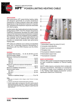
- 1. Product Specificati ons HPT™ p owe r-limiti ng Heati ng Cable 4 Construction 1 Nickel-plated copper bus wires (3.3 mm2) 2 Composite metal alloy/fibre 3 Heater bus connection (not shown) 4 Fibreglass braid 5 Fluoropolymer dielectric insulation 6 Nickel-plated copper braid 7 Fluoropolymer overjacket Basic Accessories Thermon offers system accessories designed specifically for rapid, trouble-free installation of Thermon heating cables. All HPT cables require a connection kits to comply with approval requirements. Information on accessories to complete a heater circuit installation can be found in the “Heating Cable Systems Accessories” product specification sheet (Form TEP0010U). Application High performance HPT power-limiting heating cables are designed specifically for process temperature maintenance or freeze protection where high maintain temperatures or high temperature exposure is required. HPT withstands the temperature exposures associated with steam purging. A coiled resistor alloy heating element provides the power-limiting feature of HPT. This PTC (Positive Temperature Coefficient) characteristic decreases the cable’s power output as the heat-traced product temperature increases and allows the cable to be overlapped during installation. The composite construction of the heating element and fibre substrate, plus an additional fibre cushion layer, provides an exceptionally durable high performance heating cable. HPT cables are certified for use in ordinary (nonclassified) areas and in potentially explosive atmospheres in accordance with the ATEX Directive and the IECEx Scheme. Ratings Available Watt densities......15, 30, 45, 60 W/m at 10°C Nominal supply voltage 1 .................................. 230 Vac Maximum maintenance temperature HPT-5...............................................................215°C HPT-10.............................................................195°C HPT-15.............................................................180°C HPT-20.............................................................150°C Maximum continuous exposure temperature Power-off..........................................................260°C Minimum installation temperature.........................-60°C Minimum bend radius @ -15°C.......................................................... 10 mm @ -60°C .........................................................32 mm T-rating 2 Based on stabilised design 3 .........................T2 to T6 Notes 1. Cable may be energised at other voltages; contact Thermon for design assistance. 2. T-rating per internationally recognised testing agency guidelines. 3. Thermon heating cables are approved for the listed T-ratings using the stabilised design method. This enables the cable to operate in hazardous areas without limiting thermostats. The T-rating may be determined using CompuTrace® Electric Heat Tracing Design Software or contact Thermon for design assistance. THERMON The Heat Tracing Specialists® European 1 2 5 6 7 Tel: +44 (0)191 490 1547 Fax: +44 (0)191 477 5371 Email: northernsales@thorneandderrick.co.uk Website: www.heattracing.co.uk www.thorneanderrick.co.uk
- 2. Product Specificati ons HPT™ p owe r-limiti ng Heati ng Cable Power Output Curves 1 The power outputs shown apply to overjacketed cable installed on insulated metallic pipe at the service voltage stated below. Circuit Breaker Sizing 2 Maximum circuit lengths for various circuit breaker amperages are shown below. Circuit breaker sizing and earth-fault protection should be based on applicable local codes. For information on design and performance on other voltages, contact Thermon. Earth-fault protection of equipment should be provided for each branch circuit supplying electric heating equipment. Notes 1. Maximum circuit lengths shown are based on an instantaneous trip current characteristic per IEC 60898 at the referenced start-up temperature and a 10°C maintenance temperature. For maximum circuit lengths with other trip current characteristics contact Thermon. 2. While a heat tracing system is generally designed to keep the contents of a pipe at the desired maintain temperature, the cable may be energized at lower temperatures. For design data with lower start-up temperatures than represented above contact Thermon for design assistance. 3. The maximum circuit length is for one continuous length of cable, not the sum of segments of cable. Refer to CompuTrace® design software or contact Thermon for current loading of segments. Product Type 230 Vac Nominal Zone Length cm Power Output at 10ºC W/m HPT 5-2 76 15 HPT 10-2 61 30 HPT 15-2 61 45 HPT 20-2 61 60 Type B and C Circuit Breakers 230 Vac Service Voltage Max. Circuit Length 3 vs. Breaker Size Product Start-Up Metres Temperature 2 Type °C 16 A 25 A 32 A 40 A 50 A HPT 5-2 10 167 271 0 167 271 -20 167 271 -40 167 271 HPT 10-2 10 85 136 180 191 0 85 136 180 191 -20 85 136 180 191 -40 85 136 180 191 HPT 15-2 10 57 92 120 155 156 0 57 92 120 155 156 -20 57 92 120 155 156 -40 57 92 120 155 156 HPT 20-2 10 44 70 91 117 130 0 44 70 90 116 130 -20 42 67 86 110 130 -40 40 64 82 105 130 HPT 20-2 HPT 15-2 HPT 10-2 HPT 5-2 HPT at 230 Vac 60 50 40 10 30 60 90 120 150 180 210 Pipe Temperature °C Watts per Metre 70 30 20 10 0 Certifications/Approvals II 2 G Ex e II T2 to T6, II 2 D Ex tD A21 T300°C to T85°C M 07ATEX0028 International Electrotechnical Commission IEC Certification Scheme for Explosive Atmospheres FMG 06.0006 Factory Mutual Research Ordinary and Hazardous (Classified) L ocations Underwriters L aboratories Inc. Hazardous (Classified) L ocations HPT has additional hazardous area approvals including: • DNV • L loyd’s • JIS • CCE/CMR S • GG TN Contact Thermon for additional approvals and specific information. Tel: +44 (0)191 490 1547 Fax: +44 (0)191 477 5371 Email: northernsales@thorneandderrick.co.uk Website: www.heattracing.co.uk www.thorneanderrick.co.uk