3. 3
Microprocessor v.s. Microcontroller
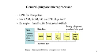
Microprocessor
• CPU is stand-alone,
RAM, ROM, I/O, timer
are separate
• designer can decide on
the amount of ROM,
RAM and I/O ports.
• expansive
• versatility
• general-purpose
Microcontroller
• CPU, RAM, ROM, I/O
and timer are all on a
single chip
• fix amount of on-chip
ROM, RAM, I/O ports
• for applications in which
cost, power and space
are critical
• single-purpose
4. 4
Embedded System
• Embedded system means the processor is embedded into that application.
• An embedded product uses a microprocessor or microcontroller to do
one task only.
• In an embedded system, there is only one application software that is
typically burned into ROM.
• Example:printer, keyboard, video game player
• Example:Table 1-1, some embedded products using microconrollers
5. 5
Three criteria in Choosing a Microcontroller
1. meeting the computing needs of the task efficiently and cost effectively
• speed, the amount of ROM and RAM, the number of I/O ports and timers, size,
packaging, power consumption
• easy to upgrade
• cost per unit
2. availability of software development tools
• assemblers, debuggers, C compilers, emulator, simulator, technical support
3. wide availability and reliable sources of the microcontrollers.
6.
7. • A single chip computer or a CPU with all the peripherals like RAM,ROM,I/O,
Timers, ADCs, etc on the same chips.
• A Microcontroller is meant to be more self- contained and independent, and
functions ads a tiny, dedicated computer.
• Originally, 8051 Microcontrollers were developed using N-MOS Technology but
the use of battery powered devices and their low power consumption lead to
usage of CMOS Technology (which is famous for its low power consumption).
• Majority of the modern 8051 Microcontrollers are Silicon IP Cores (Intellectual
Property Cores) but discrete 8051 Microcontroller IC’s are also available.
Because of their low power consumption, smaller size and simple architecture,
8051 IP Cores are used in FPGAs (Field Programmable Gate Array) and SoCs
(System on Chip) instead of Advanced ARM Architecture based MCUs.
INTRODUCTION
8. FEATURES OF 8051
• Useful for small computing tasks.
• Adequate for many control and monitoring
application.
• Packaging (RAM, ROM, Timers on chip).
• Less power consumption.
• Easily upgradable.
• Availability of tools of microcontroller such as
proteus (simulator) and keil (compiler).
12. 12
Inside Architecture of 8051
CPU
On-chip
RAM
On-chip
ROM for
program
code
4 I/O Ports
Timer 0
Serial
Port
Figure 1-2. Inside the 8051 Microcontroller Block Diagram
OSC
Interrupt
Control
External interrupts
Timer 1
Timer/Counter
Bus
Control
TxD RxD
P0 P1 P2 P3
Address/Data
Counter
Inputs
13.
14.
15.
16.
17. •The 8051 is an accumulator based microcontroller. Its registers are:
register A, PSW, register B, 8-bit stack pointer, 16-bit data pointer,
program counter, program address register, 16-bit timer registers for
timer/counters, instruction register, control registers, RAM address
register, serial data buffer, capture registers, special function registers
etc.,
•Register B is used during multiply and divide operations.
•Data pointer: It consists of DPH( a high byte) and DPL(a low byte). It holds
16- bit address. It can be used as a 16-bit register or a two independent 8-
bit registers.
•Serial Data Buffer: It consists of two separate registers, a transmit buffer
register and a receive buffer register.
•Timer Registers: (TL0,TH0), (TL1,TH1), and (TL2,TH2) are register pairs.
These register pain are 16-bit counting registers for Timer/counter 0,1, and 2
respectively.
REGISTERS: OF 8051
18. Program Counter: The Intel 8051 microcontroller contains a
16-bit program counter (PC) register. It points to the
address of the next instruction of the program which is to be
fetched and executed. It is automatically incremented after
fetching an instruction. It keeps the track of memory
addresses of the instructions in the program being
executed. It is affected by JUMP and CALL instructions.
•Stack pointer (SP): Intel 8051 microcontroller contains
an 8-bit stack pointer register. It is incremented before
data is stored during PUSH and CALL operations. It is
decremented when POP or RET (Return) operation takes
place. Any area of on-chip RAM can be used.
19. •PSW (Program Status Word): PSW register contains program status
information. Its bits are indicated by PSW.0, PSW.1, PSW.2,…….., PSW.7
7 6 5 4 3 2 1 0
Bit No. 0, PSW.0. It is for parity status (Parity flag, P).
Bit No. 1, PSW.1. Reserved.
Bit No. 2, PSW.2. Overflow flag (OV).
Bit No. 3, PSW.3. (RS0)
Bit No. 4, PSW.4. (RS1)
Bit No. 5, PSW.5. It is Flag 0 (F0) available to users for general
purpose.
Bit No. 6, PSW.6. It is auxiliary carry flag (AC).
Bit No. 7, PSW.7. It is carry flag (CY).
CY AC F0 RS1 RSO OV - P Status
information
Bit No
These bits are to select working register bank.