Module 1 Behaviour of RC beams in Shear and Torsion
•Descargar como PPTX, PDF•
22 recomendaciones•17,884 vistas

AS PER IS 456 Visit https://teacherinneed.wordpress.com/ for PDF version

Recomendados
Recomendados
Más contenido relacionado
La actualidad más candente
La actualidad más candente (20)
Similar a Module 1 Behaviour of RC beams in Shear and Torsion
Similar a Module 1 Behaviour of RC beams in Shear and Torsion (20)
Último
Último (20)
Module 1 Behaviour of RC beams in Shear and Torsion
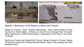
- 1. Module 1: Behaviour of RC Beams in Shear and Torsion: Modes of Cracking , Shear Transfer Mechanisms , Shear Failure Modes, Critical Sections for Shear Design , Influence of Axial Force on Design Shear Strength, Shear Resistance of Web Reinforcement, Compression Field Theory, Strut-and- Tie Model. Equilibrium Torsion and Compatibility Torsion, Design Strength in Torsion, Design Torsional Strength with Torsional Reinforcement- Space Truss Analogy and Skew Bending Theory SHEAR TORSION
- 2. 1. Flexural and shear stresses in prismatic beams Flexural (normal) stress fx and the Shear stress at any point in the section, located at a distance y from the neutral axis, are given by: I = second moment of area of the section about the neutral axis Q = first moment of area about the neutral axis of the portion of the section above the layer at distance y from the NA b = width of the beam at the layer at which is calculated. variation of shear stress is parabolic, with a maximum value at the neutral axis and zero values at the top and bottom of the section.
- 3. Combined flexural and shear stresses can be resolved into equivalent principal stresses f1 and f2 acting on orthogonal planes, inclined at an angle a to the beam axis Principal stresses
- 4. for elements located at the neutral axis – Condition of Pure Shear exists , τ is maximum and fx = 0 , f1 = f2 = τmax and α = 45o Principal stress trajectories’ are a set of orthogonal curves whose tangent/normal at any point indicate the directions of the principal stresses at that point Principal stress trajectories Principal Tensile Stress (PTS) Trajectory Principal Compressive Stress Trajectory Potential crack pattern . Principal Compressive Stress Trajectory takes the form of an arch while that of tensile stresses have the curve of a catenary or like a suspended chain. Towards midspan where shear stresses are low and bending dominant the direction of principal stresses tend to be parallel to the beam axis. Near the supports where the shearing forces are greater, the principal stresses become inclined and greater the shear force greater is the inclination. Cracks would develop in a direction that is perpendicular to that of the principal tensile stress.
- 6. 2. Modes of Cracking in RC Beams Two types of inclined cracking occur in concrete beams Web Shear Cracking Flexure – Shear Cracking Web Shear cracking starts from near NA location when the PTS due to shear exceed the tensile strength of concrete. Usually occur in I beams (thin webs) Flexure – Shear cracking is an extension of vertical flexural cracking and develops when the PTS due to combined shear and flexural tensile stresses exceed the tensile strength of concrete.
- 7. 3. Shear failure modes in beams without web rebars Case 1: a/d < 1 DEEP BEAMS Without web reinforcement, inclined cracking transforms the beam into a tied-arch with tension element as longitudinal rebars and compression element as cracked concrete The tension element may fail by yielding, fracture or failure of anchorage. OR compression chord may fail by crushing of concrete a
- 8. Case 2: 1 < a/d < 2.5 Failure is initiated by an inclined crack ⎯ usually a flexure-shear crack. The actual failure may take place either by (1) crushing of the reduced concrete section above the tip of the crack under combined shear and compression, termed shear-compression failure (2)or secondary cracking along the tension reinforcement, termed shear -tension failure. Such failures usually occur before the failure due to moment resisting capacity of beam is exhausted a a
- 9. Case 3: 2.5 < a/d < 6 If shear reinforcement is not provided, the cracks extend rapidly to the top of the beam; the failure occurs suddenly and is termed diagonal tension failure. Addition of web reinforcement enhances the shear strength considerably. Loads can be carried until failure occurs in a shear-tension mode (yielding of the shear reinforcement) or in a shear-compression mode (If shear reinforcement is excessive, it may not yield; instead concrete in diagonal compression gets crushed), or in a flexural mode. The limiting a/d ratio above which flexural failure is certain depends on the tension steel area as well as strength of concrete and steel. This is expected with a/d 6 Such beams may fail either in shear or in flexure. Flexural tension cracks develop early. Failure in shear occurs by the propagation of inclined flexural-shear cracks. a
- 10. Note: Web−Crushing Failure I−beams with web reinforcement may fail by the crushing of concrete in the web portion between the inclined cracks under diagonal compression forces
- 11. 4. Shear Transfer Mechanisms Interface shear (aggregate interlock) force Va , transmitted along the inclined plane of the crack, resulting from the friction against relative slip between the interlocking surfaces of the crack. Its contribution can be significant, if the crack-width is limited. Shear resistance in reinforced concrete beams is provided by the shear transfer in the compression zone, aggregate interlock across crack face, stirrups crossing the shear crack, and dowel action of longitudinal reinforcing bars crossing the crack in concrete c
- 12. Dowel force in the tension reinforcement (due to dowel action) Vd V = Vc + Va + Vd + Vs = Vint In the uncracked stage the applied shear is resisted almost entirely by concrete . V Vc At the instance of flexural cracking, there is a redistribution of stresses, and some interface shear Va and dowel action Vd are induced At the stage of diagonal tension cracking, the shear reinforcement that intercepts the crack contributes significantly to resist shear. All the four major mechanisms are effective at this stage.
- 13. V = Vc + Va + Vd + Vs = Vint Since methods to include Vay and Vd are not clearly available only two primary mechanisms are considered in practice. Vc is modified to take into account of Va and Vd V = Vc + Vs
- 14. The increase in pt in the flexural tension zone contributes to enhanced dowel action Vd , and control the propagation of flexural cracks. This results in increase in the position of the neutral axis The increased area of uncracked concrete in compression zone enhances contributions of Va and Vc Thus the higher the percentage tension reinforcement, the greater the shear resistance in the concrete – up to a limit : Xu /d = Xu,max/d This contribution is given in Table 19 of IS 456 which are computed from 5. Influence of Longitudinal Rebars content ; pt – 100 Ast / bd
- 15. For a concrete grade beyond a value of pt which corresponds to =1, c remains constant . This is the upper limit of contribution that can be expected from dowel action and control of crack propagation (increased depth of NA) Detailing provisions as per CL 26.2.2 and 26.2.3 are satisfied in regions of rebar curtailment
- 16. 6 Concept of Shear Span With Mand Vas the applied bending moment and shear force at a section in the beam (b x d) fx∝M /bd2 and τ ∝ V/bd 𝑓𝑥 𝜏 ∝ 𝑀 𝑉𝑑 With beams in four point bending M = Pa and V = P M/V = a -> Shear Span 𝑓𝑥 𝜏 ∝ 𝑎 𝑑 P P SHEAR SPAN The dimensionless ratio a/d or M / V d enables the prediction of failure modes of beam in flexural shear
- 17. 7. Concept of Nominal Shear Stress V/BD = (1.5 V/BD)(2/3) Average Shear Stress A. Members with Uniform Depth The concept of average shear stress in a beam section is used in mechanics of materials is used in RC sections also v = shear force / area of cross section = Vu / bd CL 40.1 τv is merely a parameter intended to aid design and to control shear stresses in RC members It does not actually represent the true average shear stress as distribution is quite complex in RC.
- 18. B. Members with Varying Depth
- 19. Note on Computation of Nominal Shear Stress When the depth increases in the same direction as the bending moment as in the case in cantilever beams, nominal shear stress is reduced. Use of the simpler equation for nominal shear stress gives conservative results. Equation as per CL 40.1.1 is mandatory when the depth decreases with increasing moment. Compression face is sloping - tapered footings and cantilever beams A similar correction is necessary and equations holds good in this case also. Use of the simpler equation for nominal shear stress gives conservative results.
- 20. When a support reaction introduces transverse compression in the end region of the member, the shear strength of this region is enhanced, and inclined cracks do not develop near the face of the support (which is usually the location of maximum shear). This is of particular significance in footing slabs where flexural (one-way) shear is a major design consideration 8. Critical sections for shear computation Critical Section for Shear (22.6.2) Support Region
- 21. Critical Section for Shear (22.6.2.1) (Crack Initiation Plane) Support Region d 450 End Region subjected to transverse compression, inclined cracks do not develop in this region Line of Dispersion Critical Section for Shear (22.6.2.1) (Crack Initiation Plane) Support Region d 450 End Region subjected to transverse compression, inclined cracks do not develop in this region Line of Dispersion > 2d
- 22. End Supported beam Critical section at d from the face of support Beam Supported by columns Concentrated Load within d from the face of support Critical section at the face of supportMember Loaded near the bottom (Inverted T beam) Beam Supported by girder of similar depth Critical section at the face of support Beam Supported by monolithic vertical element (Suspenders)
- 23. 9. Influence of Axial Force on Design Shear Strength Axial force either compression or tension may act in conjunction with M and V due to reasons such as externally applied, prestressing and restraint forces due to shrinkage or temperature. Typical examples include ring beams in domes Shear strength of concrete is generally improved in the presence of uniaxial compression and weakened in the presence of uniaxial tension. Effect of Axial Compression The effect of an axial compressive force is to delay the formation of both flexural and inclined cracks, and also to decrease the angle of inclination α of the inclined cracks to the longitudinal axis. IS 456 specifies that the design shear strength in the presence of axial compression should be taken as δ τc
- 24. Axial tensile force is expected to do exactly the reverse - it will decrease the shear strength, accelerate the process of cracking and increase the angle α of the inclined cracks. Effect of Axial Tension No explicit provisions in IS 456 are available The following simplified expression for δ, based on the ACI Code may be used: When axial tension is also present, design for shear may be done based on the Compression Field Theory or the Strut-and-Tie Model,
- 25. 10. Enhanced Shear Strength of Sections Close to Supports Shear strength of concrete is enhanced in regions close to the support, when the support reaction introduces transverse compression. Substantial portion of the load is transmitted to the support directly through strut action, rather than through flexural shear. > 300 300 d d/tan30 = 1.732 d 2d
- 26. CL 40.5.1 Enhancement of Shear Strength in end region (40.5.1) < 2d > 300
- 27. EXAMPLE 1 B = 300mm, d = 610 mm, D = 685mm, fck = 25MPa, P = 445 kN at mid span, Ast = 2458 mm2, Span = 1220 mm Find the maximum shear strength of concrete if 1. No Axial forces are present 2. If Axial compression = 265 kN Case 1: No Axial forces are present 1. av = 610 < 2d , failure plane is inclined at angle greater than 300 and concentrated load is acting in shear span (<2d). Hence critical section for shear is located in regions closer to support. 2. As per CL 40.5.1 design shear strength is enhanced to 2dc /av 3. 100 Ast/bd = 100 x 2458 / (300 x 610) = 1.34% From Table 19 c = 0.7 + [(0.74 - 0.7) x 0.09/0.25] = 0.714 N/mm2 Enhanced design Shear Strength c = 2 x 610 x 0.714 /610 = 1.428 N/mm2 4. Shear Strength of Concrete = 1.428 x 300 x 610 = 261 kN
- 28. Case 2: Axial compression = 265 kN 1. As pert CL 40.2.2 𝛿 = 1 + 3𝑃𝑢 𝐴 𝑔 𝑓𝑐𝑘 ≤ 1.5 ; 𝛿 = 1 + 3 𝑥 265 𝑥 1000 300 𝑥 685 𝑥 25 = 1.155 2. Enhanced design Shear Strength: c = 1.155 x 1.428 = 1.65 N/mm2 3. Strength of Concrete = 1.65 x 300 x 610 = 302 kN
- 29. Example 2 - Enhanced design shear strength Vu = 700 kN b = 400 mm d = 644 mm fck = 35 MPa Ast = 5 x 804.25 = 4021 mm2 1. av = 750 < 2d , failure plane is inclined at angle greater than 300 and concentrated load is acting in shear span. Hence critical section for shear is located in regions closer to support 2. As per CL 40.5.1 design shear strength is enhanced to 2dc /av 3. 100 Ast / bd = 100 x 4021 / (400 x 644) = 1.56% 1.5%, From Table 19 c = 0.78 N/mm2 Enhanced design Shear Strength c = 2 x 644 x 0.78 /750 = 1.34 N/mm2
- 30. 11. Shear Reinforcement Flexural member should be capable of developing its full moment capacity rather than having its strength limited by premature shear failure. Further in an overloading scenario failure should not be sudden and explosive in nature. Special shear reinforcement is used to enhance shear strength and induce ductile failure mechanism. Shear reinforcement, also known as web reinforcement may consist of any one of the following systems. Ends anchored properly around longitudinal bars to develop the yield strength in tension As per Cl. 40.4 • stirrups perpendicular to the beam axis; • stirrups inclined (at 45° or more) to the beam axis • longitudinal bars bent-up (usually, not more than) at 45° to 60° to the beam axis, combined with stirrups.
- 32. 12. Shear Resistance of Stirrups A. Plane Truss Model This is evaluated based on idealization of a RC beam as a plane truss consisting of a series of reinforcing steel tensile ties and concrete compressive struts, interconnected at nodes to form a truss capable of transmitting the loads to the supports. Crack pattern due to flexure and shear Original Truss model Truss is formed by lumping all the stirrups cut by section aa into one vertical member and all diagonal concrete struts cut by section bb into one compression diagonal inclined at 450 Variable angle Truss model Angle of inclination of concrete struts generally varies from 250 to 650 depending upon arrangement of rebars.
- 33. B. Beams with Inclined Stirrups Diagonal Crack with horizontal projection ‘p’ and inclined length, i= p/cos, is crossed by inclined bars, horizontally spaced ‘sv ‘apart. Let rebar inclination = a , crack orientation= and ‘a’ be the distance between successive rebars measured parallel to the crack direction. a a sv A B C D AB = a cos BD = a sin BC = BD cot a = a sin cot a AC = sv = a cos + a sin cot a = a sin ( cot + cot a) a = sv / sin ( cot + cot a)
- 34. Let ‘n’ be the number of bars crossing the crack ; n= i/a n = [p / cos] sin ( cot + cot a) / sv n = p [ 1 + tan cot a]/ sv Total shear resistance , Vus = n x fy x Asv x sin a Vus = fy Asv p [sin a + cos a tan ] / sv Assuming usual crack inclination 450 and p d and fy = 0.87 fy Vus = 0.87fy Asv d [sin a + cos a] / sv C. Beams with vertical Stirrups a =900 IS 456 CL 40.4 recommendations Vus = 0.87 fy Asv d / sv D. Beams with Inclined bars ( Bent-up) Vus = 0.87 fy Asv sin a
- 35. 13. Limits of shear rebars or Limiting value of Ultimate Shear Resistance of concrete Cl. 40.2.3 has imposed a limit on the resistance Vus from shear reinforcement, by limiting the ultimate shear resistance of concrete to c,max values given in Table 20. 𝝉 𝒄 𝒎𝒂𝒙 ≈ 𝟎. 𝟔𝟐 𝒇 𝒄𝒌 if c < v < c max , then resistance from rebars can be supplemented else section need to be redesigned Hence, a shear -compression failure may occur even before the shear reinforcement has yielded . Yielding of the shear reinforcement at the ultimate limit state is essential to ensure a ductile failure. However, such a failure will not occur if the shear reinforcement provided is excessive as section becomes stronger in diagonal tension compared to diagonal compression
- 36. 1. v= Vu/bd = 700 x 103 / (400 x 644) = 2.72N/mm2 <c max= 3.7 N/mm2 (Table 20) 2. c< v <c max , Hence Shear rebars are required 3. As per CL 40.5.2 𝐴 𝑠 = 𝑎 𝑣 𝑏 (𝜏 𝑣 − 2𝑑 𝜏 𝑐 𝑎 𝑣 ) 0.87 𝑓𝑦 = 750 𝑥 400(2.72−1.34) 0.87𝑥 415 = 1147 mm2 𝐴 𝑠≥ 0.4 𝑎 𝑣 𝑏 0.87 𝑓𝑦 = 0.4 𝑥 750 𝑥 400 0.87𝑥 415 = 333 mm2 This is provided in middle three quarters of shear span = (¾)x 750 = 563 mm Use 2L - # 12, Asv = 226 mm2 Number of stirrups = 1147/226 = 5, Spacing = 563/4 = 140 mm c/c Example 3 : Design shear reinforcement for Example 2 560
- 37. Example 4 : Verify the adequacy of RC beam in shear with following design data 3000 CL 660 1-#25 + 2-#20 2-#20 b = 250mm, d = 399 mm, D = 450 mm DL = 15.0 kN/m, LL = 13.1 kN/m fy = 415 MPa, fck = 25 MPa Shear Rebars = 8 @ 200, fy = 250MPa Support width = 230 mm 1. Ultimate shear Vu at different sections At support CL = (15 + 13.1) x3 = 84.3 kN , At midspan = 0 At curtailment location = 84.3 x (3 - 0.66) / 3 = 65.754 kN At critical section ; d from support face = 84.3 x (3 - 0.115 - 0.399) / 3 = 69.9 kN CL 22.6.21. 84.3 399 Critical section for Shear At curtailment location
- 38. 2. Check adequacy of section • v = Vu / (bd) = 69.9 x1000 / (230 x 399) = 0.76 Mpa < τc,max = 3.1 MPa (for M 25 concrete). BEAM size OK 3. Design shear resistance at critical section • Ast = 2- #20 = 628 mm2 , pt = 100 Ast/bd = 100 x 628 /( 250 x399) = 0.63 ; Table 19 - τc = 0.536 MPa • Shear Resistance of Concrete : Vc = 0.536 x 250 x 399 = 53.47 kN • Shear Resistance by Stirrups: Vus = 0.87 x 250 x 2 x 50.26 x 399 / 200 = 43.62 kN CL 40.4 • Vs = Vc + Vus = 97.1 kN > 69.9 KN OK 4. Check for Asv min and Sv max • Asv min / Sv = 0.4 x 250 /(0.87 x 250) = 0.46 • Asv prov / Sv = 2 x 50.26 / 200 = 0.5 > 0.46 OK
- 39. Sv max = 0.75 x 399 = 299 mm or 300 mm whichever is less Sv prov = 200 < 299 OK 5. Check shear strength at bar cut-off point CL 26.2.3.2 • Max. Shear resistance of beam = 97.1 kN • (2/3) x 97.1 = 64.73 kN • At curtailment location Vu = 65.754 kN > 64.73 Cl 26.2.3.2 (a) • Hence additional stirrup area is provided along terminated bar over a distance from the cutoff point = (3/4)d = 300 mm Cl 26.2.3.2 (b) • Area of cutoff bar (1-#25) = 491 mm2 • Total Area of bar at cutoff section (1-#25 + 2 - #20) = 1119 mm2 • b = 491 / 1119 = 0.44 , S = 399 /( 8 x 0.44) = 113 mm • Excess stirrup area required = 0.4 x 250 x 113 / 250 = 45 mm2 • Provide 4 nos – 2L - #8 @ 100 over a length = 300 mm in curtailed zone
- 40. CL 660 1-#25 + 2-#202-#20 300 4 - 2L - #8 @ 100 extra stps 3000
- 41. 14. Comments: IS code method , “Vc + Vs” approach is essentially empirical and generally leads to safe designs. Vc – concrete contribution is considered as some combination of force transfer by dowel action of the main steel, aggregate interlock along a diagonal crack and shear in the uncracked concrete beyond the end of the crack without an explicit account of each contribution. Diagonal cracking load without web rebars is considered as concrete contribution to the shear strength Some rational models such as “truss model”, “Strut and Tie model” and “Compression field theory are available to study the behaviour in combined bending and shear
- 42. 15. Strut and Tie Model RC beams can be divided into • B – regions where beam theory is valid and • D – regions where discontinuities ( near concentrated loads, openings and changes in cross section) which affect member behaviour D – regions are that portion of the member that is within a distance equal to member depth from a force or geometric discontinuity – Filled regions in fig B – regions are portions of member outside D – region – unfilled regions in fig.
- 43. Strut and Tie models are applied within D-regions Model consist of struts and ties connected at nodal zones that are capable of transferring loads to the supports or adjacent B regions. Thickness ‘b’ is perpendicular to the plane of truss and width ‘w’ is in the plane The truss representing the strut and tie model must fit within the envelope defined by the D region. Selection left to the discretion and multiple solutions are possible.
- 44. All of the supports and loads are within D of each other or the supports. Entire structure is characterized as D - region Example of a Transfer Girder
- 45. 16. Torsion in RC members • RC members are also subjected to torsional moments in addition to bending and shear and sometimes with axial forces also. • Torsional moments causes twisting of the member • Torsional moments can be generated in two types of load transfer mechanisms and are identified as 1.Primary or equilibrium or statically determinate torsion 2. Secondary or Compatibility or statically indeterminate torsion torsion
- 46. • exists when external load has no alternative load path but must be supported by torsion. In such cases torsion is required to maintain static equilibrium and can be uniquely determined. Example : 1. Cantilevered slab from a beam • Loads applied to the slab surface cause twisting moment mt to act along the length of beam. • These are equilibrated by the resisting torque T at the columns. • In the absence of torsional moments structure will collapse • Hence this cannot be ignored in designs A. Equilibrium torsion
- 47. 2. Curved Beams in Plan GRID Semi Circular Beam Circular Ring Beam
- 48. • arises from the requirements of compatibility of deformation between adjacent parts of a structure • Torsional moments cannot be found based on static equilibrium alone. • Ignoring this will lead to cracking but will not cause collapse. • Internal redistribution of forces is forced and an alternative equilibrium path is found Example : Spandrel or edge beam supporting a monolithic concrete slab Case1: Torsionally stiff and suitably reinforced the slab moments will be same as those for a rigid support. Case2: Little torsional stiffness and inadequate reinforcement cracking will occur and the slab moments will be same as those for a hinged support. B. Compatibility Torsion
- 49. The torsional rigidity = G C, of a member may be obtained by assuming the shear modulus G equal to 0.4 Ec , and torsional stiffness C equal to half of the St. Venant value calculated for the plain concrete section
- 50. 17. Behaviour of Plain Concrete members in torsion • The maximum torsional shear stress occurs at the middle of the wider face • The state of pure shear develops direct tensile and compressive stresses along the diagonal directions, as shown in the element at A • The principal tensile and compressive stress trajectories spiral around the beam in orthogonal directions at 45o to the beam axis. (a) (b) A • Torsion induces shear stresses and causes warping of non-circular sections. • For rectangular sections under elastic behaviour, the Distribution of torsonal shear stress over the cross- section is as shown in fig (b)
- 51. Cracks would develop on the surface when the diagonal tensile stress reaches the tensile strength of concrete and rapidly progress inwards. In a plain concrete member, the diagonal torsional cracking in the outer fibers would lead, almost immediately, to a sudden failure of the entire section.
- 52. At the cracking load, point A, the angle of twist increases without an increase in torque as some of the forces resisted by the uncracked concrete are redistributed to the reinforcement. The cracking extends toward the central core of the member, rendering the core ineffective. Experiments performed on a series of solid and hollow rectangular beams with the same exterior size and increasing amounts of both longitudinal and stirrup reinforcement, it has been found that • Although the cracking torque was lower for the hollow beams, the ultimate strengths were the same for solid and hollow beams having the same reinforcement. 18. Behaviour of RC members in torsion
- 53. After the cracking of a reinforced beam, failure may occur in several ways. • The stirrups, or longitudinal reinforcement, or both, may yield • or for beams that are over reinforced in torsion, the concrete between the inclined cracks may be crushed by principal compression stresses prior to yielding of steel. Addition of longitudinal steel without stirrups has little effect on the strength of a beam loaded in torsion because it is effective only in resisting the longitudinal component of the diagonal tension forces. A rectangular beam with longitudinal bars in the corners and closed stirrups can resist increased load after cracking NOTE:
- 54. 19. Strength of reinforced concrete members subjected to torsion Two very different theories are used The first, based on a skew bending theory developed by Lessig and extended by Hsu was the basis for the torsion-design provisions in the 1971 through 1989 ACI Codes. This theory assumes that some shear and torsion is resisted by the concrete, the rest by shear and torsion reinforcement. The mode of failure is assumed to involve bending on a skew surface resulting from the crack’s spiraling around three of the four sides of the member. IS 456 code provisions are based on this theory.
- 55. The second design theory is based on a thin-walled tube/plastic space truss model, similar to the plastic-truss analogy. This theory, presented by Lampert and Thürlimann and by Lampert and Collins, forms the basis of the torsion provisions in the latest European design recommendations for structural concrete and, since 1995, in the ACI Code.
- 56. 20. Shear Force due to Torsion in Plain Concrete beams- Plasticity Approach Assumption: Plain Concrete section is fully plasticized at the point of failure and this implies that the shear stress is constant throughout the section • Triangular area = (b x b/2)/2 = b2/4 • Vh = t b2/4 • Trapezoidal area = (b/2) [D+ (D-b)] /2 = b (2D –b)/4 • Vv= t b (2D –b)/4 • Lever arm Z1 = (D-b) + 2 𝟐 𝟑 𝒃 𝟐 = D – 𝒃 𝟑 • Lever arm Z2 = 2x(D-b+2D)/(D-b + D)b/6 = 𝒃 𝟑 𝟑𝑫−𝒃 𝟐𝑫−𝒃
- 57. Tcr = Vh z1 + Vv z 2 =t 𝒃 𝟐 𝟐 (D – 𝒃 𝟑 ) t = 𝟐 𝑻𝒄𝒓 𝒃 𝟐 (𝑫− 𝒃 𝟑 ) = 𝟐 𝑻𝒄𝒓 𝒃 𝟐 𝒅 ( 𝐃 𝐝 − 𝒃 𝟑𝐝 ) ( 𝑫 𝐝 − 𝒃 𝟑𝐝 ) 1 for most of sections in practice Since full plastificationis not justified for concrete a correction factor = 0.8 is applied t =1.6 𝑻 𝒄𝒓 𝒃 𝟐 𝒅 = 1.6 𝑻 𝒄𝒓 /𝒃 𝒃𝒅
- 58. • 1.6 Tcr /b provides a measure of the equivalent flexural shear due to torsion. • This concept is used in IS 456 to compute equivalent shear force due to transverse shear force and torsion. Shear force due to Torsion Vt = t bd= 𝟏. 𝟔 𝑻 𝒄𝒓 𝒃
- 59. Estimate the ‘cracking torque’ for a plain concrete beam 300 x 500 mm deep . Also determine the limiting torque beyond which torsional reinforcement is required. τc= 0.3 MPa, M20, τt = 0.2 fck , d = 450 mm EXAMPLE 5 1. t = 1.6 𝑻 𝒄𝒓/𝒃 𝒃𝒅 • t = 0.2 x 20 = 0.894 MPa • Tcr = t b2d /1.6 = 0.894x 3002x450/1.6 = 22.64 kNm 2. Torsional reinforcement is required if V> c, As Vu=0 • Ve = 1.6 Tu/b ; c x b xd = 1.6 Tu/b • Tu=c b2d /1.6 = 0.3 x 3002 x 450 /1.6 = 7.6 kNm
- 60. is an extension of the plane truss analogy used to explain flexural shear resistance of RC sections 21. Space Truss Analogy – Behaviour of RC members in Torsion RC member is visualized as a space truss consisting of • Spiral concrete diagonals that are able to take load parallel but not perpendicular to the torsional cracks • Transverse tension tie members provided by closed stirrups • Tension Chords provided by longitudinal reinforcement
- 61. Visualized as ‘thin-walled tube’ which is fully effective at the post- torsional cracking phase. Represents a simplification of actual behaviour as the calculated torsional strength is controlled by the strength of transverse reinforcement and is independent of concrete strength.
- 62. • Let As = area of longitudinal rebars, Asv = area of 2L stirrups, Sv = spacing of stirrups, fy = yield stress, • F be the force in each leg and link of stirrups • Torsional Moment = Tu = F b1 + F d1 • F = 0.87 fy (Asv/2) for each vertical leg and horizontal link • Number of vertical legs crossing the crack = d1 / Sv • Number of horizontal links crossing the crack = b1/ Sv • Tus= 0.87 fy (Asv/2) (d1 / Sv ) b1 + 0.87 fy (Asv/2) (b1 / Sv ) d1 22.Torsional resistance by the stirrups: Tus Sv TUS= 0.87 fy Asv b1 d1 / Sv
- 63. 23. Behaviour in Combined Shear + Torsion The flexural shear is distributed, whereas the torsional shear is restricted in the shear flow zone. In the central region, the shear is insignificant due to torsion Thus, when shear and torsion act together they are not additive throughout the width of the web.
- 64. In general, the interaction between Tu /Tus and Vu /Vus : Tu = factored twisting moment carried by stirrups Vu = factored shear force carried by stirrups Tus= Torsional shear resistance by stirrup (pure torsion) Vus = Flexural Shear resistance by stirrups (without torsion) a = values in the range 1 to 2 𝑻 𝒖 𝑻 𝒖𝒔 a + 𝑽 𝒖 𝑽 𝒖𝒔 a = 1 a = 1 , Linear interaction provides a conservative estimate
- 65. 24. Interaction formula for Shear and Torsion Assume Shear carried by stirrups = 0.4 Vu and a = 1 ; TUS= 0.87 fy Asv b1 d1 / Sv ; Vus = 0.87 fy Asv d / sv 𝑻 𝒖 𝑻 𝒖𝒔 + 𝑽 𝒖 𝑽 𝒖𝒔 = 1 𝑻 𝒖 𝑺 𝒗 𝟎.𝟖𝟕 𝒇𝒚 𝒃 𝟏 𝒅 𝟏 𝑨 𝒔𝒗 + 𝟎.𝟒 𝑽𝒖 𝑺𝒗 𝟎.𝟖𝟕 𝒇𝒚 𝑨𝒔𝒗 𝒅 = 1 𝑻 𝒖 𝑺 𝒗 𝒃 𝟏 𝒅 𝟏 (𝟎.𝟖𝟕 𝒇𝒚)𝑨 𝒔𝒗 + 𝑽 𝒖 𝑺𝒗 𝟐.𝟓 𝒅 (𝟎.𝟖𝟕 𝒇 𝒚 ) 𝑨𝒔𝒗 = 1 This is used to compute Asv as per CL 41.4.3 with d d1
- 66. Torsion causes an axial tensile force N. Fig(a) Half of this is assumed to be resisted by flexural compression zone and the other half by flexural tension steel. Flexure causes a compression–tension couple Fig (b) For combined bending and torsion, these internal forces add together. 25. Behaviour in Combined Bending + Torsion + = C - N/2 T + N/2
- 67. The reinforcement provided for the flexural tension force, T, and that provided for the tension force due to torsion (N/2) must be added together. The concept of equivalent moment as adopted in IS 456 is based on this hypothesis. In the flexural compression zone, the force C tends to cancel out some, or all, of the tension (N/2) due to torsion Fig (c)
- 68. Failure hypothesis : • Longitudinal bars and Stirrups yield simultaneously • Crack inclination = 450 Condition : (Volume of steel / unit length) x fy is same for both longitudinal and stirrups This Yields Ast Sv fy = Asv fy (b1 + d1) ; Ast = Asv (b1 + d1) /Sv Mt= (N/2) d1 = (Ast x 0.87 fy x d1) / 2 = (Asv (b1 + d1) /Sv) 0.87 fy d1 / 2 26. Equivalent Moment (Fictitious Moment) due to torsion : MT N/4 N/4
- 69. Since TUS= 0.87 fy Asv b1 d1 / Sv ; 0.87 fy Asv / Sv = Tus /b1d1 Mt = (Tus /b1d1 ) (b1 + d1) d1 / 2 = Tus(1 + d1/b1)/2 Since d1/b1 = D/b Mt = (Tus / 2)(1+ D/b) As a conservative estimate IS 456 has adopted 1.7 instead of 2 in the above expression – CL 41.4.2
- 70. 27. Combined Bending + Shear + Torsion Normal stress is caused by bending moment Shear stress due to torsion circulates around the section in different directions Shear stress due to shear force is mainly parallel to the direction of the shear force
- 71. The side of the section where the shear stresses are additive is critical in design. In general longitudinal and transverse reinforcements are required to resist all load conditions Reinforced concrete members are analysed using the space-truss analogy and the skew bending theory as per IS 456
- 72. She proposed an approach of analysis for under-reinforced beams. Equilibrium conditions for an assumed skew-bending type of failure mechanism is established. She presented the first two modes of failure Inclined tension crack spiral round three faces of the beam. On the fourth side, the ends of the crack are joined by a compression zone. At failure, reinforcement is assumed to be yielding on the three sides. A. Skew Bending Theory – proposed by Lessig (1958)
- 73. Collins et al. (1968) discovered mode 3 failure and extended the analysis to a more general case of un-symmetrically reinforced members where the top longitudinal steel is significantly less than the bottom longitudinal steel and subjected to large torque and small bending moment. Cracks are initiated at the top and side faces and the compression zone is at the bottom face. Failure occurs when both top and transverse steels yield.
- 74. The skew-bending model categorizes torsional failure of a reinforced concrete beam under three different modes: Modes 1, 2 and 3 depending on the location of a skewed compression zone near the top, side or bottom of the section respectively. Each mode has a compression face and a tension face as in the case of pure bending, but the compression face becomes skewed to the normal cross-section due to the presence of torsion. The failure pattern depends on • the aspect ratio of the beam, • the ratio between top and bottom longitudinal reinforcements, • and the ratio between applied torsional moment and bending moment in combination with different values of shear force.
- 77. The presence of shear may cause a beam to fail at a strength below that predicted by one of the three skew bending modes. In a square beam with equal longitudinal steel in all faces, under pure torsion, there would be equal possibility of failure in mode 1, 2 and 3.
- 78. Summary about Skew Bending Theory In the mode one failure, the equivalent ultimate moment (Me1) acts in the same direction as that of the flexural moment. We design the steel for Me1 If the torsional effect is large, Mt > Mu, in that case, we should also design for the transverse bending and negative bending. For the negative bending moment, we are designing for the top steel and here the equivalent moment Me2 acts in an opposite sense to that flexural moment. The transverse bending is modeled by the expression Me3 and for that there is compression in one side and tension in the other side face. The design steel is for one side face and we provide a symmetric amount of steel in the other side phase.
- 79. Mode 1 Failure Analysis Equating the internal and external moments • As1 = Area of longitudinal steel on face 1 - flexure tension face • (jd)1 = Lever arm when longitudinal steel As1 yields - is taken as that corresponding to flexure without torsion. • As1 (0.87fy)(jd)1 = equivalent bending moment = Me1 to be resisted • a varies from 450 to 900 - conservative value = 450 Me1 = M + M t
- 80. This forms the basis for computing longitudinal reinforcement as per CL 41.4.2
- 81. Mode 2 Failure Analysis Only the outer two legs of the closed stirrups should be considered for computing the torsional resistance contribution by web steel. If the stirrup consists of more than two legs, the interior legs should be ignored. This clause consists of two requirements.
- 82. The first one corresponds to the expression given for computing Asv and is intended to take care of a mode 2 failure which is likely due to large amount of torsion and small shear forces. The second requirement imposes a minimum limit so that the shear stress (ve - c) will be carried by the stirrup. This is intended for avoiding the normal type of shear failure associated with large shears together with a small amount of torsion.
- 83. Mode 3 Failure Analysis From moment equilibrium conditions As3 = Longitudinal steel on face 3 (jd)3 = Lever arm when As3 starts yielding Me2 = As3 (0.87 fy) (jd)3 = Mt - M In other words the section should resist an equivalent bending moment Me2 to avoid mode 3 failure.
- 84. 28. Detailing of Torsion Rebars
- 85. A beam, framing between columns, has an effective span of 5.0 m and supports a cantilevered projection, 1 m wide as shown in Fig. Beam size = 300 x 500 mm. Determine the adequacy of the section (as per IS Code), assuming a total uniformly distributed load (DL+LL) of 5 kN/m2 on the cantilever projection as shown. Assume fixity at the ends of the beam against torsion as well as flexure. Rebar Details: 2=#16 at top and bottom; 2L- #10@150 . M20 , d= 452 mm, Clear Cover = 30 mm on all sides measured to stirrups Example 6 1 m 5m 300 1. Loads on Beam kN/m • from projection: 5.0 × 1 = 5.0 • self weight: 25 × 0.3 × 0.5 = 3.75 kN/m • Total factored load = 1.5 x 8.75 = 13.13 kN/m • Distributed Factored torque = 5 x 0.65 x 1.5 = 4.88 kNm/m
- 86. wu = 13.13 kN/m tu= 4.88 kNm/m 2. Actions on the beam • Support section is critical as it is subjected to Mu+Vu+Tu • Mu = 13.13 x 52/12 = 27.35 kNm • Tu = 4.88 x 5/2 = 12.2 kNm • Vu = 13.13 x5/2 = 32.83 kN 3.Adequacy with respect to Longitudinal rebars • 𝒙 𝒖 𝒅 = 𝟎.𝟖𝟕 𝒙 𝟒𝟏𝟓 𝒙 𝟒𝟎𝟐 𝟎.𝟑𝟔 𝒙 𝟐𝟎 𝒙 𝟑𝟎𝟎 𝒙 𝟒𝟓𝟐 = 𝟎. 𝟏𝟓< xu max/d = 0.48 • 𝑴𝒐𝒎𝒆𝒏𝒕 𝒐𝒇 𝑹𝒆𝒔𝒊𝒔𝒕𝒂𝒏𝒄𝒆 𝑴 𝒖 = 𝟎. 𝟖𝟕 𝒇 𝒚 𝑨 𝒔𝒕 𝒅(𝟏 − 𝑨 𝒔𝒕 𝒇 𝒚 𝒃𝒅𝒇 𝒄𝒌 ) = 61.6 kNm
- 87. • Equivalent moment Me1 = Mu + Mt • Mt = Tu ( 1 + D/B)/1.7 cl 41.4.2 = 12.2 ( 1+ 500/300)/1.7 = 19.14 kNm • Me1 = 27.35 + 19.14 = 46.49 kNm < 61.6 Longitudinal reinforcement on tension face is adequate • Mt < Mu ; Me2=0; Longitudinal reinforcement on compression face is not necessary
- 88. 4. Need for Shear rebars • Equivalent Shear as per CL 41.3.1 • Ve = Vu + 1.6 (Tu/b) = 32.83 + 1.6 (12.2/0.3) = 98 kN • ve = 98 x 103 / (300 x462) = 0.71 MPa • c max = 2.8 MPa Table 20 • pt = 100 x402/(300x462) = 0.29 , Table 19 , c = 0.383MPa • c < ve < c max ; Shear rebars are necessary
- 89. 5. Check for adequacy of 2L - 10@150 CL 41.4.3 Condition 1 𝑨 𝒔𝒗 = 𝑻 𝒖 𝑺 𝒗 𝒃 𝟏 𝒅 𝟏(𝟎. 𝟖𝟕 𝒇𝒚) + 𝑽 𝒖 𝑺𝒗 𝟐. 𝟓 𝒅 𝟏 (𝟎. 𝟖𝟕 𝒇𝒚) Assume clear cover = 30 mm b1 = 300 – (30 +10 + 8)2 = 204 mm ; d1= 500 – (30 + 10 + 8)2 = 404 mm Asv = 𝟏𝟐.𝟐 𝒙𝟏𝟎𝟔 𝒙 𝟏𝟓𝟎 𝟐𝟎𝟒𝒙 𝟒𝟎𝟒 𝒙 𝟎.𝟖𝟕 𝒙 𝟒𝟏𝟓 + 𝟑𝟐.𝟖𝟑𝒙𝟏𝟎𝟑𝒙𝟏𝟓𝟎 𝟐.𝟓 𝒙 𝟒𝟎𝟒 𝒙 𝟎.𝟖𝟕 𝒙 𝟒𝟏𝟓 = 75 mm2 < 2 x 78.54 = 157 mm2 , OK b1 d1
- 90. Condition 2 Asv > (ve- c)b Sv / 0.87 fy = (0.71- 0.383)x 300 x1 50 / 0.87 x 415 = 40.75 mm2 < 2 x 78.54 = 157 mm2 , OK 6. Check for Spacing compliance: CL 26.5.1.7 (a) x1 y1 • Sv = 150 mm (provided) • x1 = 300 - 60 -10 = 230 • y1 = 500 - 60 -10 = 430 • Sv x1 = 230 (x1 + y1) /4 = 165 300 Provided Spacing = 150 mm is OK 30
- 91. 7. Adequacy of side face reinforcement : CL 26.5.1.7 (b), 26.5.1.3 • D = 500 > 450 mm Side face reinforcement is necessary • Area of Rebars = 0.1% web area =0.001 bD = 0.001 x 300 x 500 = 150 mm2 • Area on each face = 75 mm2 ; Spacing 300 or b=300 • Provide # 10 in the middle on each face • As = 78.5 mm2 > 75 mm2, Spacing = 202mm 202 202 2-#16 2-#16 1-#10 2L -#10@150
- 92. Design the torsional reinforcement in a rectangular beam section, 350 x 750 mm deep, subjected to an ultimate twisting moment of 140 kNm, combined with an ultimate (hogging) bending moment of 200 kNm and an ultimate shear force of 110kN. Assume M 25 concrete, Fe 415 steel and mild exposure conditions. 1. Design data • B = 350mm, D = 750mm , Tu =140 kNm, Mu = 200 kNm, Vu =110kN, fck=25MPa,fy=415MPa • Minimum Cover =20 mm (table 16) to outside face of stirrups • Assume effective cover to main rebars =50 mm • d = 700 mm Example 7
- 93. 2. Design for Combined Bending and Torsion – Longitudinal Rebars : CL 41.4.2 • 𝐌𝐭 = 𝐓𝐮 𝟏+ 𝐃 𝐛 𝟏.𝟕 = 𝟏𝟒𝟎 𝟏+ 𝟕𝟓𝟎 𝟑𝟓𝟎 𝟏.𝟕 = 259 kNm • Me1 = Mu+ Mt =200 +259 = 459 kNm causes flexural tension at top • Mu,lim = 0.36x0.48( 1- 0.42 x 0.48) 350x7002 x25 = 591.5 kNm > 459 kNm • Adequate to provide rebars only on tension face(singly reinforced)
- 94. • 𝑴 𝒖 = 𝟎. 𝟖𝟕 𝒇 𝒚 𝑨 𝒔𝒕 𝒅(𝟏 − 𝑨 𝒔𝒕 𝒇 𝒚 𝒃𝒅𝒇 𝒄𝒌 ) • 17.12 𝑨 𝒔𝒕 2 -252735 𝑨 𝒔𝒕+459 x 106 = 0 ; Ast = 2121 mm2 • Provide 4 – #20 + 2-#25 ; Ast = 2236 mm2 at top CL 41.4.2.1 • Mt> Mu , longitudinal reinforcement is provided on the flexural compression face also. • Me2 = Mt – Mu = 59 kNm • 17.12 𝑨 𝒔𝒕 2 -252735 𝑨 𝒔𝒕+59 x 106 = 0 ; Ast = 238 mm2 • Ast,min = (0.85/415) x 350 x 700 = 502 mm2 CL 26.5.1.1 (a) • Provide 3 – #16 ; Ast = 603 mm2 at bottom
- 95. 3. Design for Combined Shear and Torsion – Transverse Rebars CL 41.3.1 • Ve = Vu + 1.6 Tu/b = 110 + 1.6 (140/0.35) = 750 kN • ve = 750 x103 / (350 x700) = 3.06 MPa CL 40.1 < 3.1 MPa (Table 20) • 100 Ast/bd = 100 x 2236 /(350x700) = 0.913 • c = 0.62 MPa (Table 19) • c <ve <c max ; Shear rebars are necessary
- 96. CL 41.4.3 Condition 1 • 𝑨 𝒔𝒗 𝑺 𝒗 = 𝑻 𝒖 𝒃 𝟏 𝒅 𝟏 (𝟎.𝟖𝟕 𝒇𝒚) + 𝑽 𝒖 𝟐.𝟓 𝒅 𝟏 (𝟎.𝟖𝟕 𝒇𝒚) • effective cover = 50 mm on all sides (measured to center of bars) • b1= 250 mm ; d1= 650 mm • 𝑨 𝒔𝒗 𝑺 𝒗 = 𝟏𝟒𝟎𝒙𝟏𝟎𝟔 𝟐𝟓𝟎𝒙 𝟔𝟓𝟎 𝒙 𝟎.𝟖𝟕 𝒙 𝟒𝟏𝟓 + 𝟏𝟏𝟎𝒙𝟏𝟎𝟑 𝟐.𝟓 𝒙 𝟔𝟓𝟎 𝒙 𝟎.𝟖𝟕 𝒙 𝟒𝟏𝟓 = 2.58 b1 d1 50 50
- 97. Condition 2 • 𝑨 𝒔𝒗 𝑺 𝒗 > (3.06− 0.62)350 0.87 x 415 = 2.37 • Adopt 𝑨 𝒔𝒗 𝑺 𝒗 = 2.58 • Assume 2L - #12 , Asv = 226 mm2 • Sv = 226/2.58 = 87 mm 𝑨 𝒔𝒗 𝑺 𝒗 > (ve− c)b 0.87 fy
- 98. 4. Check for Spacing compliance: CL 26.5.1.7 (a) • x1 = 250 + 25 + 12 = 287 • y1 = 650 + 25 +12 = 687 • Sv x1 = 287 (x1 + y1) /4 = 243 300 • Adopt 2L - #12 @ 85 mm b1 = 250 d1 = 650 50 50 2-#25 + 2-#20 2-#20 3 - #16
- 99. 5. Adequacy of side face reinforcement : CL 26.5.1.7 (b), 26.5.1.3 • D = 750 > 450 mm Side face reinforcement is necessary • Area of Rebars = 0.1% web area =0.001 bD = 0.001 x 350 x 750 = 263mm2 • Area on each face = 132 mm2 ; Spacing 300 or b=350 • Provide 2 - # 10 in the middle zone on each face • As = 157 mm2 > 132 mm2, Spacing = 250 mm 50 50 2-#25 + 2-#20 2-#20 3 - #16 2-#10 2-#10 250 2L - #12 @ 85
- 100. Example 8 A reinforced concrete rectangular beam b = 300 mm, d = 600 mm and D = 650 mm is subjected to factored shear force Vu = 70 kN, Mu = 215 kNm (sagging),Tu = 100 kNm. Assume M 30 concrete,Fe415 steel design the reinforcement. 1. Design data • B = 300mm, D = 650mm , Tu =100 kNm, Mu = 215 kNm, Vu =70kN, fck=30MPa,fy=415MPa • d = 600 mm • effective cover = 50 mm
- 101. Step 1: Design for Combined Bending and Torsion – Longitudinal Rebars CL 41.4.2 • Me1 = Mu + Mt = Mu + (Tu /1.7) {1 + (D/b)} • Me1 = 215 + (100 / 1.7) { 1 + (650/300)} = 215 + 186.3 • Me1 = 401.3 kNm • Mu,lim = 0.36x0.48(1- 0.42x0.48)x300x6002x30 / 106 = 447 kNm > Me1 Adequate to provide rebars only on tension face(singly reinforced)
- 102. As per CL G 1.1 (b) determine Ast 401.3x106 = 0.87x415xAstx600(1 - Ast x 415 / (300x600x30)) = 216630 Ast – 16.65 Ast2 16.65 Ast2 - 216630 Ast + 401.3x106 = 0 • Ast = 2237 mm2 • provide 5 - #25 (2454 mm2) at bottom CL 41.4.2.1 • Mt < Mu , longitudinal reinforcement is not required on the flexural compression face • Provide 3 - #12
- 103. 3. Design for Combined Shear and Torsion – Transverse Rebars Cl 41.3.1 • Ve = Vu + 1.6 (Tu/b) • Ve = 70 + 1.6 (100/0.30 ) = 603 kN • ve = 603 x1000/(300x600) = 3.35 MPa <c,max= 3.5 MPa (TABLE 20) • 100 Ast/ bd = 100 x 2454 / (300 x600) = 1.36 • Table 19, c = 0.735 MPa • c < ve < c max ; Shear rebars are necessary
- 104. CL 41.4.3 Condition 1 • 𝑨 𝒔𝒗 𝑺 𝒗 = 𝑻 𝒖 𝒃 𝟏 𝒅 𝟏 (𝟎.𝟖𝟕 𝒇𝒚) + 𝑽 𝒖 𝟐.𝟓 𝒅 𝟏 (𝟎.𝟖𝟕 𝒇𝒚) • effective cover = 50 mm on all sides (measured to center of bars) • b1= 200 mm ; d1= 550 mm • 𝑨 𝒔𝒗 𝑺 𝒗 = 𝟏𝟎𝟎𝒙𝟏𝟎𝟔 𝟐𝟎𝟎𝒙 𝟓𝟓𝟎 𝒙 𝟎.𝟖𝟕 𝒙 𝟒𝟏𝟓 + 𝟕𝟎𝒙𝟏𝟎𝟑 𝟐.𝟓 𝒙 𝟓𝟓𝟎 𝒙 𝟎.𝟖𝟕 𝒙 𝟒𝟏𝟓 = 2.66 b1 d1 50 50
- 105. Condition 2 • 𝑨 𝒔𝒗 𝑺 𝒗 > (3.35− 0.735)300 0.87 x 415 = 2.17 • Adopt 𝑨 𝒔𝒗 𝑺 𝒗 = 2.66 • Assume 2L - #12 , Asv = 226 mm2 • Sv = 226/2.66 = 85 mm 𝑨 𝒔𝒗 𝑺 𝒗 > (ve− c)b 0.87 fy
- 106. 4. Check for Spacing compliance: CL 26.5.1.7 (a) • x1 = 200 + 25 + 12 = 237 • y1 = 550 + 25 +12 = 587 • Sv x1 = 237 (x1 + y1) /4 = 206 300 • Adopt 2L - #12 @ 85 mm b1 d1 50 50
- 107. 5. Adequacy of side face reinforcement : CL 26.5.1.7 (b), 26.5.1.3 • D = 750 > 450 mm Side face reinforcement is necessary • Area of Rebars = 0.1% web area =0.001 bD = 0.001 x 300 x 650 = 195mm2 • Area on each face = 98 mm2 ; Spacing 300 or b=300 • Provide 2 - # 10 in the middle zone on each face • As = 156 mm2 > 98 mm2, Spacing = 200 mm 50 50 3-#25 2-#25 3 - #12 2-#10 2-#10 200 2L - #12 @ 85 300 650
- 108. Example 9 Calculate the resistance in pure torsion of a RC beam rectangular in section 250 x 300 mm deep with 2-#10 at top and 2-#12 at bottom at an effective cover = 35 mm. Stirrups = 2L- #10 @ 150 mm c/c; M20 and Fe415. Flexural Compression face is at top. Step 1: For pure torsion: Vu=0,Mu=0 and torsional resistance is the least of • Mode1 Failure due to Me1 • Mode2 Failure due to Ve • Mode3 Failure due to Me2 • Since Ast at top is < Ast at bottom , Me2 < Me1 - Hence Mode 3 failure is possible Step 2: Tu based on Me2 – Mode 3 failure • Ast = 2-#10 = 157 mm2 ; d = 300-35 = 265 mm • xu/d = (0.87 x 415 x 157) /(0.36 x 20 x 250 x 265) = 0.12 CL G-1.1(a) • xu/d < xu max /d = 0.48 , Under reinforced CL 38.1 • Me2 = 0.87 x 415 x 157 x 265 [ 1- {157 x 415/(250x265x20)}] = 14.3 kNm CL G-1.1(b)
- 109. • Me2 = Mt - Mu = Mt = 14.3 kNm • Mt = Tu [ 1+ (D/b)]/1.7 • Tu = 14.3 x 1.7 / [ 1 +(300/250)] = 11.05 KNm Step 2: Tu based on Ve – Mode 2 failure • Asv = 157 mm2 , Vu=0, SV= 150 mm, b1 = 250-70 = 180 mm, d1=300 -70 =230mm • 𝑨 𝒔𝒗 𝑺 𝒗 = 𝑻 𝒖 𝒃 𝟏 𝒅 𝟏(𝟎.𝟖𝟕 𝒇𝒚) ; Tu = 𝑨 𝒔𝒗 𝑺 𝒗 𝒃 𝟏 𝒅 𝟏 𝒙 𝟎. 𝟖𝟕 𝒇𝒚 • Tu = 𝟏𝟓𝟕 𝟏𝟓𝟎 𝒙 180 𝑥 230 𝑥 0.87 𝑥 415 =15.64 kNm • Resistance to torsion = Min (11.05,15.64) = 11.05 kNm
- 110. Example 10 A RC beam 230 x 400 is reinforced with 3-#16 at top and 4-#20 at bottom with an effective cover= 35 mm. The beam is subjected to Mu= 42 kNm, Vu= 10 kN. Compute the possible torsion that the beam can resist.. Also design the shear reinforcement.M20 and Fe415 grade steel. Step 1: Check beam behaviour • Xu max /d = 0.87 fy Ast lim /0.36fck b d • Ast lim = 0.48 x 0.36 x 20 x 230 x 365/0.87x415 = 804 mm2 < 4 x 314 = 1256 mm2 • Beam is doubly reinforced • Ast1 = 804 mm2 ; Ast2 = 1256 - 804 = 452 mm2 • fsc = Ast2 x 0.87 fy / Asc = 452 x 0.87 x 415 /3 x 201 = 270 N/mm2 Step 2: Compute Resistance Moment MR • MR = Mu lim + fsc Asc (d-d’) • Mu lim = 0.36 x 0.48 ( 1- 0.42 x 0.48)230 x 3652x20/106 = 84.6 kNm • MR = 84.6 + (270 x 3x201x(365-35))/106 = 138.3 kNm
- 111. Step 3: Tu based on Mode1 failure • Me1 = MR = Mu + Mt • Mt = Me1- Mu = 138.3 – 42 = 96.3 kNm • Mt = Tu ( 1+D/b)/1.7 • Tu = 96.3 x1.7 /( 1+400/230) = 59.77 kNm Step 4: Tu based on Mode3 failure (Reverse Bending) • Ast = 3-#16 = 603 mm2 < 804 mm2 • Beam behaves as singly reinforced • MR = 0.87 x 415 x 603 x 365 x [1 – 603 x 415/(230 x 365 x20)] = 67.6 kNm • Me2 = MR = Mt – Mu • Mt = 67.6 + 42 = 109.6 kNm • Tu = 109.6 x1.7 /( 1+400/230) = 68 kNm
- 112. Step 5: Tu based on Mode2 failures • Ve = Vu + 1.6 Tu/b CL 41.3.1 • c max = 2.8MPa Table 20 • Ve max = c max x b x d = 2.8 x 230 x 365/1000 = 235 kN • Tu max = (235-10) x 0.23/1.6 = 32 kNm • Max Possible Tu beam can resist = Min (59.77,68,32) • As a conservative estimate TU is restricted to 30 kNm Step 6 : Design of Shear Reinforcement • Ve = 10 + 1.6 x 30/0.23 = 219kN • ve = 219 x 103 /(230 x 365) = 2.6 MPa < c max OK • pt = 100 x 4 x 301 /(230 x365) = 1.44 % • c 0.72MPa
- 113. CL 41.4.3 Condition 1 • 𝑨 𝒔𝒗 𝑺 𝒗 = 𝑻 𝒖 𝒃 𝟏 𝒅 𝟏 (𝟎.𝟖𝟕 𝒇𝒚) + 𝑽 𝒖 𝟐.𝟓 𝒅 𝟏 (𝟎.𝟖𝟕 𝒇𝒚) • effective cover = 35 mm on all sides (measured to center of bars) • b1= 160 mm ; d1= 330 mm • 𝑨 𝒔𝒗 𝑺 𝒗 = 𝟑𝟎𝒙𝟏𝟎𝟔 𝟏𝟔𝟎𝒙 𝟑𝟑𝟎 𝒙 𝟎.𝟖𝟕 𝒙 𝟒𝟏𝟓 + 𝟏𝟎𝒙𝟏𝟎𝟑 𝟐.𝟓 𝒙 𝟑𝟑𝟎 𝒙 𝟎.𝟖𝟕 𝒙 𝟒𝟏𝟓 = 1.6
- 114. Condition 2 • 𝑨 𝒔𝒗 𝑺 𝒗 > (2.6− 0.72)230 0.87 x 415 = 1.2 • Adopt 𝑨 𝒔𝒗 𝑺 𝒗 = 1.6 • Assume 2L - #12 , Asv = 226 mm2 • Sv = 226/1.6 = 140 mm 𝑨 𝒔𝒗 𝑺 𝒗 > (ve− c)b 0.87 fy
- 115. 4. Check for Spacing compliance: CL 26.5.1.7 (a) • x1 = 160 + 20 + 12 = 192 • y1 = 330 + 20 +12 = 362 • Sv x1 = 192 (x1 + y1) /4 = 138 300 • Adopt 2L - #12 @ 130 mm
- 116. Example 11 Design a RC beam of square section to resist a pure ultimate torque = 15 kNm, M20 and Fe415 grade steel. Step 1: For pure torsion: Vu=0,Mu=0 • Me1= Me2 = Mt = 15 x ( 1 +1)/1.7 = 17.65 kNm • Let D be the Depth required for a singly reinforced section, d = 0.85D • 17.65x103 = 0.36 x 0.48 (1- 0.42 x 0.48) x D3 x 0.852 x 20 • D = 206 mm • Adopt 250 x 250 section; d = 212.5 , effective cover = 37.5 mm Step 2: Compute Ast • 17.65x106 = 0.87x 415x Ast x 212.5( 1- Ast x 415/250 x 212.5 x 20) • 29.97Ast 2 - 76723.13Ast + 17.65x106 = 0 • Ast = 255 mm2 ; provide 3-#12, Ast = 339 mm2 at top and bottom
- 117. Step 6 : Design of Shear Reinforcement • Ve = 1.6 x 15/0.25 = 96kN • ve = 96 x 103 /(250 x 212.5) = 1.8 MPa < c max OK • pt = 100 x 339/(250 x212.5) = 0.64 % • c 0.52MPa CL 41.4.3 Condition 1 • 𝑨 𝒔𝒗 𝑺 𝒗 = 𝑻 𝒖 𝒃 𝟏 𝒅 𝟏 (𝟎.𝟖𝟕 𝒇𝒚) • effective cover = 37.5 mm on all sides (measured to center of bars) • b1= 175 mm ; d1= 175 mm • 𝑨 𝒔𝒗 𝑺 𝒗 = 𝟏𝟓𝒙𝟏𝟎𝟔 𝟏𝟕𝟓𝒙 𝟏𝟕𝟓 𝒙 𝟎.𝟖𝟕 𝒙 𝟒𝟏𝟓 = 1.36
- 118. Condition 2 • 𝑨 𝒔𝒗 𝑺 𝒗 > (1.8− 0.52)250 0.87 x 415 = 0.89 • Adopt 𝑨 𝒔𝒗 𝑺 𝒗 = 1.36 • Assume 2L - #10, Asv = 157 mm2 • Sv = 157/1.36 = 115 mm 𝑨 𝒔𝒗 𝑺 𝒗 > (ve− c)b 0.87 fy
- 119. 4. Check for Spacing compliance: CL 26.5.1.7 (a) • x1 = 175 + 12 + 10 = 197 • y1 = 197 • Sv x1 = 197 (x1 + y1) /4 = 98 300 • Adopt 2L - #10 @ 90 mm