SlideShare a Scribd company logo
1 of 14
CONTROL UNIT
CPU is partitioned into Arithmetic Logic Unit (ALU) and Control Unit (CU).
The function of control unit is to generate relevant timing and control signals to all
operations in the computer.
It controls the flow of data between the processor and memory and peripherals
Types:
There are two methods to implement the control unit:
• Hardwired: The control signals are generated as an output of a set of basic
logic gates, the input of which derives from the binary bits in the Instruction
Register.
• Microprogrammed: The control signals are generated by a microprogram
that is stored in Control Read Only Memory.
The Hardwired and Microprogrammed controlunit generates the control signals to
fetch and execute instructions. The fundamental difference between hardwired and
microprogrammed control unit is that hardwired is a circuitry approach whereas,
the microprogram control unit is implemented by programming.
HARDWIRED CONTROL UNIT
The hardwired control unit generates the control signals to execute the instructions
in a proper sequence and at the correct time. The hardwired control unit is created
with the hardware; it is a circuitry approach. It is designed for the RISC style
instruction set.
o A Hard-wired Control consists of two decoders, a sequence counter, and a
number of logic gates.
o An instruction fetched from the memory unit is placed in the instruction
register (IR).
o The component of an instruction register includes; I bit, the operation code,
and bits 0 through 11.
o The operation code in bits 12 through 14 are coded with a 3 x 8 decoder.
o The outputs of the decoder are designated by the symbols D0 through D7.
o The operation code at bit 15 is transferred to a flip-flop designated by the
symbol I.
o The operation codes from Bits 0 through 11 are applied to the control logic
gates.
o The Sequence counter (SC) can count in binary from 0 through 15.
Hardwired Control Unit block diagram
• The decoder/encoder is a combinational circuit that generates a setofrequired
control signals.
• A control step counter is used to keep track of the control steps. Each count
of this counter corresponds to one control step.
The required control signals are determined by the following information:
1. Contents of the control step counter
2. Contents of IR register
3. Contents of the condition code flags
4. External input signals, like MFC and interrupt request
• The step decoder generate a separate clock signal for each step, or timeslot,
in the control sequence.
• The instruction decoder decodes the instruction loaded in IR. The output of
the instruction decoderconsists ofa separate line for each of the ‘m’ machine
instruction
Hardwired Control Unit Design Methods
1. State-table Method
2. Delay-element Method: Uses clocked delay element (D-Flip Flop)
3. Sequence-counter Method: Uses counter for timing purposes
4. PLA Method: Uses programmable logic array
1. State-table Method
Classical method of sequential circuit design. Attempts to minimize the amount of
hardware. It starts with the construction of state transition table. In every state the
control unit generates a set of control signals.
2. Delay-element Method
Control signals or groups of control signals are activated in propersequence. There
is a specific time delay between activation of two consecutive control signals or
groups of control signal.
For synchronous operation, delay elements are implemented using D flip-flops and
controlled by common clock signal.
Rules for Delay-elementMethod
• Each sequence of two successive micro-operations requires a delay element.
• The signals that are intended to activate same control lines are logically
ORed to get one common output signals
Advantages of Hardwired Control Unit
1. Fast because control signals are generated by combinational circuits.
2. The delay in generation of control signals depends upon the number of gates
Disadvantages
1. More the control signals required by CPU, more complex will be the design
of control unit.
2. No Flexibility. Modification in control signal is very difficult i.e. it requires
rearranging of wires in the hardware circuit.
3. Difficult to add new feature in existing design of control unit
Micro-Programmed Control Unit
A micro-programmed control unit is implemented using programming approach. A
sequence of microoperations are carried out by executing a program consisting of
micro-instructions.
Micro-program, consisting of micro-instructions is stored in the control memory of
the control unit.
Execution of a micro-instruction is responsible for generation of a set of control
signals.
Important Terms
• Control Word: - The control variables at any time are represented by 1’s and
0’s, known as Control Word. Control words can be programmed to perform
various operations.
• Micro-Operations: The operations performed on the data stored inside the
registers are called micro-operations.
• Micro-Programs: Microprogramming is the concept for generating control
signals using programs. These programs are called micro-programs.
• Micro-Instructions: The instructions that make micro-program are called
micro-instructions.
• Micro-Code: Micro-program is a group of microinstructions. The micro-
program can also be termed as micro-code.
• Control Memory: Micro-programs are stored in the read only memory
(ROM). That memory is called control memory.
Micro-Programmed control Organization
1. Control Memory
2. Control Address Register
3. Sequencer (Next Address Generator)
4. Control Data Register (Pipeline Register)
Types of memory in MPC
1. Main Memory
The main memory is used for storing programs. The content of the main memory
can be altered when data is manipulated and each time the program is changed.
Program in main memory contains machine instructions and data.
2. Control Memory
Memory that is a part of the control unit is called Controlmemory. Controlmemory
holds microprograms that cannot be altered by the user. The microprogram consists
of microinstructions to execute register microoperations.
Machine instruction initiates a series of microinstructions in the control memory.
The microinstruction generates microoperations to fetch instructions from main
memory, to evaluate effective address, to execute the operations specified by
instructions or to repeat the cycle for the next instruction.
Sequencer and Pipeline Register
Sequencer: The next address generator is called a sequencer, as it determines the
address sequence that is read from the control memory.
Functions:
1. Incrementing the control register
2. Loading an address from control memory to CAR.
3. Loading an initial address
PipelineRegister: Thecontroldata register holds the present microinstruction while
the next address is computed and read from the memory. This data register is called
pipeline register.
Selection of address for Control Memory
Address Sequencing
Address Sequencing = Sequencer: Next Address Generator. Selection of address for
control memory
Routine: Microinstruction are stored in control memory in groups
Mapping
Instruction Code Address in control memory (where routine is located)
Address Sequencing Capabilities: control memory address
1. Incrementing of the control address register
2. Unconditional branch or conditional branch, depending on status bit
conditions
3. Mapping process (bits of the instruction address for control memory )
4. A facility for subroutine return
Multiplexer
1. CAR Increment
2. JMP/CALL
3. Mapping
4. Subroutine Return
Control Address Register CAR: CAR receive the address from 4 different
paths:
1. Incrementer
2. Branch address from control memory
Instruction code
Mapping
Logic
Multiplexers
Control memory (ROM)
Subroutine
Register
(SBR)
Branch
Logic
Status
Bits
Microoperations
Control Address Register
(CAR)
Incrementer
MUX
Select
Select a status
Bit
Branch address
3. Mapping Logic
4. SBR Subroutine Register
SBR Subroutine Register: Return Address cannot be stored in ROM. Return
Address for a subroutine is stored in SBR
Conditional Branching
• Status Bits: Controlthe conditional branch decisions generated in the Branch
Logic
• Branch Logic: Test the specified condition and Branch to the indicated
address if the condition is met; otherwise, the control address register is just
incremented.
Mapping of Instruction
Mapping: transformation from instruction code bits to microinstruction address in
control memory where routine is located.
Each computer instruction has its own microprogram
Routine stored in a given location of the control memory
4 bit Opcode = specify up to 16 distinct instruction
Mapping Process: Converts the 4-bit Opcode to a 7-bit control memory address
1. Place a “0” in the most significant bit of the address
2. Transfer 4-bit Operation code bits
3. Clear the two least significant bits of the CAR
Subroutine
Subroutines are programs that are used by other routines. Subroutine can be called
from any point within the main body of the microprogram
Subroutine must have a provision for:
• Storing the return address during a subroutine call
• Restoring the address during a subroutine return (Last-In First Out(LIFO)
Register Stack)
Micro-instruction Types
• Vertical Micro-Programming : Each micro-instruction specifies single (or
few) micro-operations to be performed
• Horizontal Micro-Programming : Each micro-instruction specifies many
different micro-operations to be performed in parallel
Vertical Micro-programming
• Width is narrow
• n control signals encoded into log2 n bits
• Limited ability to express parallelism
• Considerable encoding ofcontrolinformation requires external memory word
decoder to identify the exact control line being manipulated
Horizontal Micro-programming
• Wide memory word
• High degree of parallel operations possible
• Little encoding of control information
Advantages of Micoprogrammed Control Unit
1. The design of micro-program control unit is less complex because micro-
programs are implemented using software routines.
2. The micro-programmed control unit is more flexible because design
modifications, correction and enhancement is easily possible.
3. The new or modified instruction set of CPU can be easily implemented by
simply rewriting or modifying the contents of control memory.
4. The fault can be easily diagnosed in the micro-program control unit using
diagnostics tools by maintaining the contents of flags, registers and counters
Disadvantages:
1. The micro-program control unit is slower than hardwired control unit. That
means to execute an instruction in micro-program control unit requires more
time.
2. The micro-program control unit is expensive than hardwired control unit in
case of limited hardware resources.
3. The design duration of micro-program control unit is more than hardwired
control unit for smaller CPU.
Hardwired Control vs Microprogrammed Control

More Related Content

What's hot

Computer instructions
Computer instructionsComputer instructions
Computer instructions
Anuj Modi
 
Cache memory
Cache memoryCache memory
Cache memory
Anuj Modi
 
Input output organization
Input output organizationInput output organization
Input output organization
abdulugc
 
Microprogram Control
Microprogram Control Microprogram Control
Microprogram Control
Anuj Modi
 

What's hot (20)

Addressing sequencing
Addressing sequencingAddressing sequencing
Addressing sequencing
 
Register transfer language
Register transfer languageRegister transfer language
Register transfer language
 
Instruction cycle
Instruction cycleInstruction cycle
Instruction cycle
 
Micro program example
Micro program exampleMicro program example
Micro program example
 
Memory Organization
Memory OrganizationMemory Organization
Memory Organization
 
Computer instructions
Computer instructionsComputer instructions
Computer instructions
 
Micro Programmed Control Unit
Micro Programmed Control UnitMicro Programmed Control Unit
Micro Programmed Control Unit
 
Pipeline hazard
Pipeline hazardPipeline hazard
Pipeline hazard
 
Cache memory
Cache memoryCache memory
Cache memory
 
Computer architecture input output organization
Computer architecture input output organizationComputer architecture input output organization
Computer architecture input output organization
 
ADDRESSING MODES
ADDRESSING MODESADDRESSING MODES
ADDRESSING MODES
 
Input output organization
Input output organizationInput output organization
Input output organization
 
Register transfer and micro-operation
Register transfer and micro-operationRegister transfer and micro-operation
Register transfer and micro-operation
 
Memory organization (Computer architecture)
Memory organization (Computer architecture)Memory organization (Computer architecture)
Memory organization (Computer architecture)
 
Microprogram Control
Microprogram Control Microprogram Control
Microprogram Control
 
Computer instruction
Computer instructionComputer instruction
Computer instruction
 
design of accumlator
design of accumlatordesign of accumlator
design of accumlator
 
CISC & RISC Architecture
CISC & RISC Architecture CISC & RISC Architecture
CISC & RISC Architecture
 
Computer registers
Computer registersComputer registers
Computer registers
 
Direct memory access (dma)
Direct memory access (dma)Direct memory access (dma)
Direct memory access (dma)
 

Similar to Control Units : Microprogrammed and Hardwired:control unit

chapter3_CA.pptt nnnnnnnnnnnnnnnnnnnnnnn
chapter3_CA.pptt nnnnnnnnnnnnnnnnnnnnnnnchapter3_CA.pptt nnnnnnnnnnnnnnnnnnnnnnn
chapter3_CA.pptt nnnnnnnnnnnnnnnnnnnnnnn
NineTo1
 
conrol_Unit_part_of_computer_architecture.pptx
conrol_Unit_part_of_computer_architecture.pptxconrol_Unit_part_of_computer_architecture.pptx
conrol_Unit_part_of_computer_architecture.pptx
jbri1395
 
Microarchitecture
MicroarchitectureMicroarchitecture
Microarchitecture
meashi
 
Design of control unit.pptx
Design of control unit.pptxDesign of control unit.pptx
Design of control unit.pptx
Shubham014
 
Unit 3. control unit
Unit 3. control unitUnit 3. control unit
Unit 3. control unit
Kiran Bagale
 

Similar to Control Units : Microprogrammed and Hardwired:control unit (20)

chapter3_CA.pptt nnnnnnnnnnnnnnnnnnnnnnn
chapter3_CA.pptt nnnnnnnnnnnnnnnnnnnnnnnchapter3_CA.pptt nnnnnnnnnnnnnnnnnnnnnnn
chapter3_CA.pptt nnnnnnnnnnnnnnnnnnnnnnn
 
conrol_Unit_part_of_computer_architecture.pptx
conrol_Unit_part_of_computer_architecture.pptxconrol_Unit_part_of_computer_architecture.pptx
conrol_Unit_part_of_computer_architecture.pptx
 
Unit 3 CO.pptx
Unit 3 CO.pptxUnit 3 CO.pptx
Unit 3 CO.pptx
 
Unit 2
Unit 2Unit 2
Unit 2
 
Unit 2
Unit 2Unit 2
Unit 2
 
Microarchitecture
MicroarchitectureMicroarchitecture
Microarchitecture
 
CO Unit 3.pdf (Important chapter of coa)
CO Unit 3.pdf (Important chapter of coa)CO Unit 3.pdf (Important chapter of coa)
CO Unit 3.pdf (Important chapter of coa)
 
CS304PC:Computer Organization and Architecture UNIT II .pdf
CS304PC:Computer Organization and Architecture UNIT II .pdfCS304PC:Computer Organization and Architecture UNIT II .pdf
CS304PC:Computer Organization and Architecture UNIT II .pdf
 
Control unit design
Control unit designControl unit design
Control unit design
 
assignment on control unit and control signal micro instruction
assignment on control unit and control signal micro instructionassignment on control unit and control signal micro instruction
assignment on control unit and control signal micro instruction
 
Unit II.pptx
Unit II.pptxUnit II.pptx
Unit II.pptx
 
Control unit
Control unit Control unit
Control unit
 
unit-3.pdf
unit-3.pdfunit-3.pdf
unit-3.pdf
 
2.computer org.
2.computer org.2.computer org.
2.computer org.
 
Compuer organizaion processing unit
Compuer organizaion processing unitCompuer organizaion processing unit
Compuer organizaion processing unit
 
3 4- computer organization and archietecture- COA- CO- Computer organization
3 4- computer organization and archietecture- COA- CO- Computer organization3 4- computer organization and archietecture- COA- CO- Computer organization
3 4- computer organization and archietecture- COA- CO- Computer organization
 
Design of control unit.pptx
Design of control unit.pptxDesign of control unit.pptx
Design of control unit.pptx
 
Unit 3. control unit
Unit 3. control unitUnit 3. control unit
Unit 3. control unit
 
Control Memory.pptx
Control Memory.pptxControl Memory.pptx
Control Memory.pptx
 
computer architecture
computer architecturecomputer architecture
computer architecture
 

Recently uploaded

Standard vs Custom Battery Packs - Decoding the Power Play
Standard vs Custom Battery Packs - Decoding the Power PlayStandard vs Custom Battery Packs - Decoding the Power Play
Standard vs Custom Battery Packs - Decoding the Power Play
Epec Engineered Technologies
 
Cara Menggugurkan Sperma Yang Masuk Rahim Biyar Tidak Hamil
Cara Menggugurkan Sperma Yang Masuk Rahim Biyar Tidak HamilCara Menggugurkan Sperma Yang Masuk Rahim Biyar Tidak Hamil
Cara Menggugurkan Sperma Yang Masuk Rahim Biyar Tidak Hamil
Cara Menggugurkan Kandungan 087776558899
 
XXXXXXXXXXXXXXXXXXXXXXXXXXXXXXXXXXXXXXXXXXXXXXXXXXXX
XXXXXXXXXXXXXXXXXXXXXXXXXXXXXXXXXXXXXXXXXXXXXXXXXXXXXXXXXXXXXXXXXXXXXXXXXXXXXXXXXXXXXXXXXXXXXXXXXXXXXXXX
XXXXXXXXXXXXXXXXXXXXXXXXXXXXXXXXXXXXXXXXXXXXXXXXXXXX
ssuser89054b
 
Verification of thevenin's theorem for BEEE Lab (1).pptx
Verification of thevenin's theorem for BEEE Lab (1).pptxVerification of thevenin's theorem for BEEE Lab (1).pptx
Verification of thevenin's theorem for BEEE Lab (1).pptx
chumtiyababu
 
DeepFakes presentation : brief idea of DeepFakes
DeepFakes presentation : brief idea of DeepFakesDeepFakes presentation : brief idea of DeepFakes
DeepFakes presentation : brief idea of DeepFakes
MayuraD1
 

Recently uploaded (20)

Bhubaneswar🌹Call Girls Bhubaneswar ❤Komal 9777949614 💟 Full Trusted CALL GIRL...
Bhubaneswar🌹Call Girls Bhubaneswar ❤Komal 9777949614 💟 Full Trusted CALL GIRL...Bhubaneswar🌹Call Girls Bhubaneswar ❤Komal 9777949614 💟 Full Trusted CALL GIRL...
Bhubaneswar🌹Call Girls Bhubaneswar ❤Komal 9777949614 💟 Full Trusted CALL GIRL...
 
Tamil Call Girls Bhayandar WhatsApp +91-9930687706, Best Service
Tamil Call Girls Bhayandar WhatsApp +91-9930687706, Best ServiceTamil Call Girls Bhayandar WhatsApp +91-9930687706, Best Service
Tamil Call Girls Bhayandar WhatsApp +91-9930687706, Best Service
 
Introduction to Serverless with AWS Lambda
Introduction to Serverless with AWS LambdaIntroduction to Serverless with AWS Lambda
Introduction to Serverless with AWS Lambda
 
AIRCANVAS[1].pdf mini project for btech students
AIRCANVAS[1].pdf mini project for btech studentsAIRCANVAS[1].pdf mini project for btech students
AIRCANVAS[1].pdf mini project for btech students
 
Design For Accessibility: Getting it right from the start
Design For Accessibility: Getting it right from the startDesign For Accessibility: Getting it right from the start
Design For Accessibility: Getting it right from the start
 
Navigating Complexity: The Role of Trusted Partners and VIAS3D in Dassault Sy...
Navigating Complexity: The Role of Trusted Partners and VIAS3D in Dassault Sy...Navigating Complexity: The Role of Trusted Partners and VIAS3D in Dassault Sy...
Navigating Complexity: The Role of Trusted Partners and VIAS3D in Dassault Sy...
 
PE 459 LECTURE 2- natural gas basic concepts and properties
PE 459 LECTURE 2- natural gas basic concepts and propertiesPE 459 LECTURE 2- natural gas basic concepts and properties
PE 459 LECTURE 2- natural gas basic concepts and properties
 
Standard vs Custom Battery Packs - Decoding the Power Play
Standard vs Custom Battery Packs - Decoding the Power PlayStandard vs Custom Battery Packs - Decoding the Power Play
Standard vs Custom Battery Packs - Decoding the Power Play
 
kiln thermal load.pptx kiln tgermal load
kiln thermal load.pptx kiln tgermal loadkiln thermal load.pptx kiln tgermal load
kiln thermal load.pptx kiln tgermal load
 
DC MACHINE-Motoring and generation, Armature circuit equation
DC MACHINE-Motoring and generation, Armature circuit equationDC MACHINE-Motoring and generation, Armature circuit equation
DC MACHINE-Motoring and generation, Armature circuit equation
 
FEA Based Level 3 Assessment of Deformed Tanks with Fluid Induced Loads
FEA Based Level 3 Assessment of Deformed Tanks with Fluid Induced LoadsFEA Based Level 3 Assessment of Deformed Tanks with Fluid Induced Loads
FEA Based Level 3 Assessment of Deformed Tanks with Fluid Induced Loads
 
Cara Menggugurkan Sperma Yang Masuk Rahim Biyar Tidak Hamil
Cara Menggugurkan Sperma Yang Masuk Rahim Biyar Tidak HamilCara Menggugurkan Sperma Yang Masuk Rahim Biyar Tidak Hamil
Cara Menggugurkan Sperma Yang Masuk Rahim Biyar Tidak Hamil
 
XXXXXXXXXXXXXXXXXXXXXXXXXXXXXXXXXXXXXXXXXXXXXXXXXXXX
XXXXXXXXXXXXXXXXXXXXXXXXXXXXXXXXXXXXXXXXXXXXXXXXXXXXXXXXXXXXXXXXXXXXXXXXXXXXXXXXXXXXXXXXXXXXXXXXXXXXXXXX
XXXXXXXXXXXXXXXXXXXXXXXXXXXXXXXXXXXXXXXXXXXXXXXXXXXX
 
Hostel management system project report..pdf
Hostel management system project report..pdfHostel management system project report..pdf
Hostel management system project report..pdf
 
Thermal Engineering Unit - I & II . ppt
Thermal Engineering  Unit - I & II . pptThermal Engineering  Unit - I & II . ppt
Thermal Engineering Unit - I & II . ppt
 
Verification of thevenin's theorem for BEEE Lab (1).pptx
Verification of thevenin's theorem for BEEE Lab (1).pptxVerification of thevenin's theorem for BEEE Lab (1).pptx
Verification of thevenin's theorem for BEEE Lab (1).pptx
 
Thermal Engineering-R & A / C - unit - V
Thermal Engineering-R & A / C - unit - VThermal Engineering-R & A / C - unit - V
Thermal Engineering-R & A / C - unit - V
 
Block diagram reduction techniques in control systems.ppt
Block diagram reduction techniques in control systems.pptBlock diagram reduction techniques in control systems.ppt
Block diagram reduction techniques in control systems.ppt
 
DeepFakes presentation : brief idea of DeepFakes
DeepFakes presentation : brief idea of DeepFakesDeepFakes presentation : brief idea of DeepFakes
DeepFakes presentation : brief idea of DeepFakes
 
Unleashing the Power of the SORA AI lastest leap
Unleashing the Power of the SORA AI lastest leapUnleashing the Power of the SORA AI lastest leap
Unleashing the Power of the SORA AI lastest leap
 

Control Units : Microprogrammed and Hardwired:control unit

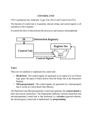
  • 1. CONTROL UNIT CPU is partitioned into Arithmetic Logic Unit (ALU) and Control Unit (CU). The function of control unit is to generate relevant timing and control signals to all operations in the computer. It controls the flow of data between the processor and memory and peripherals Types: There are two methods to implement the control unit: • Hardwired: The control signals are generated as an output of a set of basic logic gates, the input of which derives from the binary bits in the Instruction Register. • Microprogrammed: The control signals are generated by a microprogram that is stored in Control Read Only Memory. The Hardwired and Microprogrammed controlunit generates the control signals to fetch and execute instructions. The fundamental difference between hardwired and microprogrammed control unit is that hardwired is a circuitry approach whereas, the microprogram control unit is implemented by programming.
  • 2. HARDWIRED CONTROL UNIT The hardwired control unit generates the control signals to execute the instructions in a proper sequence and at the correct time. The hardwired control unit is created with the hardware; it is a circuitry approach. It is designed for the RISC style instruction set.
  • 3. o A Hard-wired Control consists of two decoders, a sequence counter, and a number of logic gates. o An instruction fetched from the memory unit is placed in the instruction register (IR). o The component of an instruction register includes; I bit, the operation code, and bits 0 through 11. o The operation code in bits 12 through 14 are coded with a 3 x 8 decoder. o The outputs of the decoder are designated by the symbols D0 through D7. o The operation code at bit 15 is transferred to a flip-flop designated by the symbol I. o The operation codes from Bits 0 through 11 are applied to the control logic gates. o The Sequence counter (SC) can count in binary from 0 through 15. Hardwired Control Unit block diagram • The decoder/encoder is a combinational circuit that generates a setofrequired control signals. • A control step counter is used to keep track of the control steps. Each count of this counter corresponds to one control step. The required control signals are determined by the following information: 1. Contents of the control step counter 2. Contents of IR register 3. Contents of the condition code flags 4. External input signals, like MFC and interrupt request • The step decoder generate a separate clock signal for each step, or timeslot, in the control sequence. • The instruction decoder decodes the instruction loaded in IR. The output of the instruction decoderconsists ofa separate line for each of the ‘m’ machine instruction
  • 4. Hardwired Control Unit Design Methods 1. State-table Method 2. Delay-element Method: Uses clocked delay element (D-Flip Flop) 3. Sequence-counter Method: Uses counter for timing purposes 4. PLA Method: Uses programmable logic array 1. State-table Method Classical method of sequential circuit design. Attempts to minimize the amount of hardware. It starts with the construction of state transition table. In every state the control unit generates a set of control signals.
  • 5. 2. Delay-element Method Control signals or groups of control signals are activated in propersequence. There is a specific time delay between activation of two consecutive control signals or groups of control signal. For synchronous operation, delay elements are implemented using D flip-flops and controlled by common clock signal. Rules for Delay-elementMethod • Each sequence of two successive micro-operations requires a delay element. • The signals that are intended to activate same control lines are logically ORed to get one common output signals Advantages of Hardwired Control Unit 1. Fast because control signals are generated by combinational circuits. 2. The delay in generation of control signals depends upon the number of gates Disadvantages 1. More the control signals required by CPU, more complex will be the design of control unit.
  • 6. 2. No Flexibility. Modification in control signal is very difficult i.e. it requires rearranging of wires in the hardware circuit. 3. Difficult to add new feature in existing design of control unit Micro-Programmed Control Unit A micro-programmed control unit is implemented using programming approach. A sequence of microoperations are carried out by executing a program consisting of micro-instructions. Micro-program, consisting of micro-instructions is stored in the control memory of the control unit. Execution of a micro-instruction is responsible for generation of a set of control signals. Important Terms • Control Word: - The control variables at any time are represented by 1’s and 0’s, known as Control Word. Control words can be programmed to perform various operations. • Micro-Operations: The operations performed on the data stored inside the registers are called micro-operations. • Micro-Programs: Microprogramming is the concept for generating control signals using programs. These programs are called micro-programs. • Micro-Instructions: The instructions that make micro-program are called micro-instructions. • Micro-Code: Micro-program is a group of microinstructions. The micro- program can also be termed as micro-code. • Control Memory: Micro-programs are stored in the read only memory (ROM). That memory is called control memory. Micro-Programmed control Organization 1. Control Memory
  • 7. 2. Control Address Register 3. Sequencer (Next Address Generator) 4. Control Data Register (Pipeline Register) Types of memory in MPC 1. Main Memory The main memory is used for storing programs. The content of the main memory can be altered when data is manipulated and each time the program is changed. Program in main memory contains machine instructions and data. 2. Control Memory Memory that is a part of the control unit is called Controlmemory. Controlmemory holds microprograms that cannot be altered by the user. The microprogram consists of microinstructions to execute register microoperations. Machine instruction initiates a series of microinstructions in the control memory. The microinstruction generates microoperations to fetch instructions from main memory, to evaluate effective address, to execute the operations specified by instructions or to repeat the cycle for the next instruction. Sequencer and Pipeline Register Sequencer: The next address generator is called a sequencer, as it determines the address sequence that is read from the control memory.
  • 8. Functions: 1. Incrementing the control register 2. Loading an address from control memory to CAR. 3. Loading an initial address PipelineRegister: Thecontroldata register holds the present microinstruction while the next address is computed and read from the memory. This data register is called pipeline register. Selection of address for Control Memory Address Sequencing Address Sequencing = Sequencer: Next Address Generator. Selection of address for control memory Routine: Microinstruction are stored in control memory in groups Mapping Instruction Code Address in control memory (where routine is located) Address Sequencing Capabilities: control memory address 1. Incrementing of the control address register 2. Unconditional branch or conditional branch, depending on status bit conditions 3. Mapping process (bits of the instruction address for control memory ) 4. A facility for subroutine return
  • 9. Multiplexer 1. CAR Increment 2. JMP/CALL 3. Mapping 4. Subroutine Return Control Address Register CAR: CAR receive the address from 4 different paths: 1. Incrementer 2. Branch address from control memory Instruction code Mapping Logic Multiplexers Control memory (ROM) Subroutine Register (SBR) Branch Logic Status Bits Microoperations Control Address Register (CAR) Incrementer MUX Select Select a status Bit Branch address
  • 10. 3. Mapping Logic 4. SBR Subroutine Register SBR Subroutine Register: Return Address cannot be stored in ROM. Return Address for a subroutine is stored in SBR Conditional Branching • Status Bits: Controlthe conditional branch decisions generated in the Branch Logic • Branch Logic: Test the specified condition and Branch to the indicated address if the condition is met; otherwise, the control address register is just incremented. Mapping of Instruction Mapping: transformation from instruction code bits to microinstruction address in control memory where routine is located. Each computer instruction has its own microprogram Routine stored in a given location of the control memory
  • 11. 4 bit Opcode = specify up to 16 distinct instruction Mapping Process: Converts the 4-bit Opcode to a 7-bit control memory address 1. Place a “0” in the most significant bit of the address 2. Transfer 4-bit Operation code bits 3. Clear the two least significant bits of the CAR Subroutine Subroutines are programs that are used by other routines. Subroutine can be called from any point within the main body of the microprogram Subroutine must have a provision for: • Storing the return address during a subroutine call • Restoring the address during a subroutine return (Last-In First Out(LIFO) Register Stack) Micro-instruction Types • Vertical Micro-Programming : Each micro-instruction specifies single (or few) micro-operations to be performed • Horizontal Micro-Programming : Each micro-instruction specifies many different micro-operations to be performed in parallel Vertical Micro-programming • Width is narrow • n control signals encoded into log2 n bits • Limited ability to express parallelism • Considerable encoding ofcontrolinformation requires external memory word decoder to identify the exact control line being manipulated
  • 12. Horizontal Micro-programming • Wide memory word • High degree of parallel operations possible • Little encoding of control information
  • 13. Advantages of Micoprogrammed Control Unit 1. The design of micro-program control unit is less complex because micro- programs are implemented using software routines. 2. The micro-programmed control unit is more flexible because design modifications, correction and enhancement is easily possible. 3. The new or modified instruction set of CPU can be easily implemented by simply rewriting or modifying the contents of control memory. 4. The fault can be easily diagnosed in the micro-program control unit using diagnostics tools by maintaining the contents of flags, registers and counters Disadvantages: 1. The micro-program control unit is slower than hardwired control unit. That means to execute an instruction in micro-program control unit requires more time. 2. The micro-program control unit is expensive than hardwired control unit in case of limited hardware resources. 3. The design duration of micro-program control unit is more than hardwired control unit for smaller CPU.
  • 14. Hardwired Control vs Microprogrammed Control