MNPS. Update Course and Advanced Techniques. Segmentation and ROIs.
•
0 likes•43 views

Update Course and Advanced Techniques in MNPS (version 10.36.07, 2019-2020). Segmentation tools and Region Of Interest (ROI) Translation into English of the original Portuguese version. MNPS is developed by Mevis Informática Médica, São Paulo, Brazil

Recommended
Recommended
More Related Content
Similar to MNPS. Update Course and Advanced Techniques. Segmentation and ROIs.
Similar to MNPS. Update Course and Advanced Techniques. Segmentation and ROIs. (20)
More from Armando Alaminos Bouza
More from Armando Alaminos Bouza (20)
Recently uploaded
Recently uploaded (20)
MNPS. Update Course and Advanced Techniques. Segmentation and ROIs.
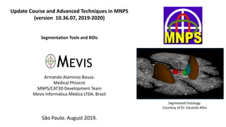
- 1. Update Course and Advanced Techniques in MNPS (version 10.36.07, 2019-2020) Segmentation Tools and ROIs Armando Alaminos Bouza. Medical Phisicist MNPS/CAT3D Development Team Mevis Informática Médica LTDA. Brasil São Paulo. August 2019. Segmented histology. Courtesy of Dr. Eduardo Alho
- 2. ROI = “Region Of Interest” “ROI” is a form of anatomical segmentation. The concept of ROI in MNPS, CAT3D, and TRACKER is associated with volume, so it is a 3D entity. An ROI is formed by one or more parallel 2D closed polygons. Usually, the most convenient way is to draw the ROIs in horizontal (axial) planes, because in this case the MNPS/CAT3D generates more useful information from the ROI. You can draw coronal or sagittal ROIs, but they will not render as 3D solids, cannot be interpolated or expanded, and have other limitations. ROI as wireframe Solid ROI Case of a neurinoma being planned for SRS
- 3. In the button bar there is an icon for open the ROIs Menu NOTE: Drawing ROIs in CAT3D is similar to MNPS, with some minor feature differences. You can draw ROIs over the MRI in CAT3D and then import these ROIs via image fusion into MNPS. MNPS allows you to draw ROIs in “Virtual Fiducials” mode and in stereotactic mode. Stereotactic mode has some restrictions on ROI tools.
- 4. Drawing an ROI with the “Draw with Pen” tool. Open the ROIs menu with the toolbar button shown below. Select “Draw with Pen”.
- 5. Select a number and color for the ROI and give it a name. The ROI name can be up to 15 characters long, longer names will be truncated.
- 6. Draw with mouse and CLICK. When you are close to closing the polygon, move to the next plane with PageUp or PageDown, or using the buttons on the drawing toolbar. After drawing on all the planes you want, finish with F10 or the raised pencil button (on the left side of the ESC). Drawing toolbar buttons
- 7. In drawing mode with “Pen”: • When you are in the middle of a contour drawing, you can erase the last strokes with the <DEL> key. • If you have already closed a contour and want to modify it, go back to the contour plane and immediately press the <INSERT> key, then click on the contour border and draw the correct path.
- 8. Drawing ROIs in “Paintbrush” mode Select “Draw with Brush” Give the new ROI a name and end with <ENTER>
- 9. “Draw with Brush” window. Toolbar buttons in order from left to right: 1. Brush to remove brush (eraser) 2. Brush to increase area 3. Increase brush diameter 4. Decrease brush diameter 5. Hide Side reconstruction 6. Erase last brush. 7. Go to previous slice 8. Go to back slice 9. Finish ROI drawing 10.Abort ROI drawing
- 10. Evolution of a drawing with “Brush”. The paintbrush mode works like a brush that fills with paint (or strips of paint) its entire cross-section. When the brush creates a closed contour, the entire inner area becomes part of the ROI. Normally you drag the brush with the left mouse button pressed. The brush diameter can be modified (+ and - ). To end a slice and move to another, use <PageUp>, <PageDown> or arrow buttons.
- 11. Automatic drawing of ROIs based on pixel intensity threshold Open ROI menu Information window in “Auto ROI segment” mode
- 12. With the left, right, up, down arrow keys, make sure that the entire edge of the structure turns pink. At this point click the mouse on the edge. MNPS creates the outline in blue. If satisfactory, press <PageUp> or <PageDown> to finish and go to another slice. At the end, close the “Auto ROI” mode with <F10> or button with raised pen.
- 13. The automatic method is suitable for cases where there is significant contrast at the edge of the structure of interest. An ROI can be created by drawing parts in automatic and parts in manual mode.
- 14. Auto ROI with user assistance (Retouch). If the contour does not close because it is connected to a neighboring structure, the “Retouch” mode can be activated. With this you can create a trace using the mouse that cuts the unwanted connection.
- 15. In cases where the automatic method can be applied, better results are obtained than the manual method in much shorter times.
- 16. Create a Spherical ROI centered on a POI.
- 17. Translation of an ROI. It's a 3D translation, it moves the entire volume
- 18. ROI drawing before having the stereotaxic image. You often have access to MRI sequences of the patient, which will be used in the fusion of images, days before surgery. MNPS in “Virtual Fiducials” mode can be used to draw the relevant volumes in advance. CAT3D can also be used. On the day of surgery, MRI and stereotactic CT are registered and fused. After you are satisfied with the result of the fusion you can import the ROIs made in CAT3D or MNPS. Open the Fusion Menu, with <ALT-F5> or through help menu. Select “Import ROIs/POIs from external Set”.
- 19. In the case of non-stereotaxic sequence, the segmentation can also be done with CAT3D. In the 2017 version, CAT3D gained multiple improvements in drawing tools. Some of these improvements are: • <CTRL-C> and <CTRL-V> in “Draw with Brush” mode • Auto segmentation now has a mode to look for 3D contours. • “Delete Segment” can delete multiple ROI segments in a row. • “Auto ROI” allows you to draw multiple segments without leaving an image plane. End a segment with <END>, in which case it continues in the same plane. • With CAT3D you can import drawings made with another system, which are recorded in DICOM-STRUCT format.
- 20. Expand or Shrink an ROI and create another new ROI. This is useful to create margins, a typical case is creating a PTV from a GTV. To shrink an ROI we use negative margin. This case is isotropic only.
- 21. Expanding an ROI, result. From GTV to PTV
- 22. ROIs are rendered in various planes and shapes.
- 23. Two ways to represent ROIs in reconstructions. With the button in the upper right corner, we switch the way to present the ROIs on the reconstructions that are on the right side of the planning window in MNPS. Segmented histology in the MNPS. Courtesy of Dr. Eduardo Alho.
- 24. Show or hide all ROIs Access to the ROIs Menu
- 25. Volume and area information of each ROI It can be used as a resource for structure volumetry
- 26. Creating a POI centered on an ROI. Method by centered on the principal axes (X, Y, Z). Technical note: It can also be defined as the center of the ROI “bounding box”. Specifically from the “Axis-Aligned Bounding Box” (AABB).
- 27. Creating a POI at the center of mass of an ROI
- 28. Example of use of the “Center of Mass” and volumetry, segmenting the sub- thalamic nucleus (STn).
- 29. Principal Axes of ROI 8 (stn-e): Center of mass (of ROI surface) : -15.737842 24.811325 57.591415 Principal axis angles : 38.000000 1.700000 Inertia Momentums (min & max) : 875.559631 2138.041748 Center of mass (of ROI surface) : -11.301948 -1.238154 -3.500875 (comissural coordinates) Inertia Axis Frontal Extreme : 25.651627 26.053579 -8.757654 (comissural coordinates) Inertia Axis Occipital Extreme : -48.255775 -28.530123 1.756322 (comissural coordinates) Principal axis angles : -126.447416 169.097154 (comissural coordinates) Center of Mass Additional information recorded by the MNPS in the MNPS.LOG file.
- 30. In some cases, the Center of Mass can be very far from the Center of Coordinates by Main Axes (CCMA). CCMA is usually best as a first approximation to the isocenter of stereotaxic radiosurgery
- 31. Operations with ROIs: Let's create the ROI intercept between the brainstem and the potential target “Neuri+2”. NOTE: This feature only works on horizontal ROIs, Z = Constant, that is Virtual Fiducials.
- 32. Result of the intersection between the brainstem and the potential target “Neuri+2”. ROI intercept in red with name “Tron DIF PTV”. The volume is 0.02 ml.
- 33. ROI smoothing. 2D methods. Kernel Average
- 34. ROI smoothing. 2D methods. Kernel Average. Result example. This is the simplest and safest method; it can be applied to oblique planes.
- 36. ROI smoothing. “Volumetric Smoothing 3D”. It is a 3D procedure; it affects ROI as volume. NOTE: This feature only works on horizontal ROIs, Z = Constant.
- 38. There is an indirect method to smooth an ROI, also as a 3D process. Do “ROI Expasion” follow by an identical “ROI Shrink”. See in the example. Blue is the original drawing, red is the <neurinoma+1mm>, in green the <neurinoma+1mm-1mm>.
- 39. Some utilities associated with ROIs - Dose assessment in radiosurgery and brachytherapy, both for targets and for organs at risk. - ROIs are essential for Dose-Volume Histograms (DVH) in radiosurgery. - Necessary for automatic optimization methods in radiosurgery and brachytherapy. - Volumetry and area measurements. - Interception of ROI and VTA generated by DBS, similarity indices. - 2D and 3D presentations. Parenchyma details do not appear in 3D without the aid of ROIs. - ROIs allow the evaluation of collision of surgical paths with a 3D volume (ventricles, vascular structures, etc.). - With the new MRI techniques, we were able to design some functional neurosurgery nuclei, such as STn, red and others. The ROI tools allow, for example, to determine the center of mass, which can result in a good target. It also allows quantitative comparison with literature maps.
- 40. Exporting ROIs in STL format. CAT3D has more features for this task.
- 41. MNPS exports ROIs in STL format that can be opened on systems that support that format. This is the way to create parts in 3D printers. ModuleWorks STL View, for Windows (www.moduleworks.com)
- 42. Sample Implant created with CAT3D, exported as STL, opened in SolidView (www.solidview.com)