
Recommended
More Related Content
What's hot
What's hot (20)
Recently uploaded
Recently uploaded (20)
APOE application diagram
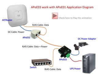
- 1. APoE03 work with APoE01 Application Diagram Check here to Play the animation AP/Router RJ45 Cable: Data DC Cable: Power APoE01 DC Power Adapter RJ45 Cable: Data + Power APoE03 Switch UPS Power RJ45 Cable: Data
- 2. APoE03 work with APoE01 Application Diagram Next AP/Router RJ45 Cable: Data DC Cable: Power Power source from Power Adapter APoE01 DC Power Adapter RJ45 Cable: Data + Power APoE03 Switch UPS Power RJ45 Cable: Data
- 3. APoE03 work with APoE01 Application Diagram EXIT Close Animation AP/Router RJ45 Cable: Data When No Power Source from Power Adapter Automatic take Power Source from UPS DC Cable: Power APoE01 DC Power Adapter RJ45 Cable: Data + Power APoE03 Switch UPS Power RJ45 Cable: Data