Temperature Resistance Sensors Guide
•
1 like•128 views

This document provides information on Watlow resistance temperature sensors, including RTDs and thermistors. It describes the key features and benefits of RTDs such as their accurate and repeatable measurements over a wide temperature range. It also lists common applications for RTDs like food equipment, textile production, and semiconductor processing. The document provides ordering information for various sensor styles with different sheath materials, lengths, element types, and termination options.

Recommended
Recommended
More Related Content
What's hot
What's hot (16)
Similar to Temperature Resistance Sensors Guide
Similar to Temperature Resistance Sensors Guide (20)
Recently uploaded
Recently uploaded (20)
Temperature Resistance Sensors Guide
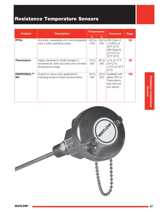
- 1. 87WATLOW® Resistance Temperature Sensors Product Description °F °C Accuracy Page RTDs Accurate, repeatable and interchangeable over a wide operating range. -328 to 1200 -200 to 650 DIN Class A ± 0.06% at 32°F (0°C) DIN Class B ±0.12% at 32°F (0°C) 88 Thermistors Highly sensitive to small changes in temperature, fairly accurate over a limited temperature range. -75 to 500 -60 to 260 ±1% at 77°F (25°C) to ±15% at 32°F (0°C) 99 ENVIROSEAL™ HD Suited for heavy-duty applications including those in harsh environments. -40 to 392 -40 to 200 Available with either RTD or Thermistors. See informa- tion above 106 Temperature ResistanceTemperature Sensors
- 2. 88 WATLOW® Termination Code Length A — B — C — J — K — L — T 11/2* U 11/2* Resistance Temperature Sensors RTDs Bends Diameter in. Standard Bend Radius in. Minimum “H” Dimension in. Minimum “C” Dimension in. 0.125 3/8 2 2 0.188 3/8 2 2 0.250 1/2 2 2 H 10 - 90° Radius C #8 Spade Lugs Length Standard Male Plug Standard Female Jack Standard Male Plug with Mating Connector Miniature Male Plug Miniature Male Plug with Mating Connector Term D Term D Length Split Leads Lead Terminations * When style contains jacketed wire. Miniature Female Jack
- 3. 89WATLOW® Resistance Temperature Sensors RTDs Fitting Options Fitting Type Material Sheath Size in. NPT Thread Size in. Hex Size in. Length in. Code 303 SS 0.063 to 0.250 1/8 7/16 11/16 A 303 SS 0.125 to 0.250 1/4 9/16 7/8 B 303 SS 0.125 to 0.250 1/2 7/8 1 D 303 SS 0.125 to 0.250 1/2 7/8 13/4 F Fitting Type Material Sheath Size in. NPT Thread Size in. Hex Size in. Length in. Code Brass 0.125 1/8 1/2 1 J 0.188 1/8 1/2 11/8 J 0.250 1/8 1/2 13/16 J 303 SS 0.063 1/8 1/2 11/4 L 0.125 1/8 1/2 11/4 L 0.188 1/8 1/2 15/16 L 0.250 1/8 1/2 15/16 L 303 SS 0.063 1/8 1/2 11/4 G 0.125 1/8 1/2 11/4 G 0.188 1/8 1/2 11/4 G 0.250 1/4 7/8 27/16 X 303 SS 0.063 1/8 1/2 11/4 Q 0.125 1/8 1/2 11/4 Q 0.188 1/8 1/2 11/4 Q 0.250 1/4 7/8 27/16 V Fixed Fittings Fixed Bayonet Fitting A LFixed Single Thread 1 ⁄8 NPT Customer Specified Fixed Bayonet Fitting A LFixed Single Thread 1 ⁄4 NPT Customer Specified Fixed Bayonet Fitting A LFixed Single Thread 1 ⁄2 NPT Customer Specified A L ixed Fittings Fixed Double Thread 1 ⁄2 NPT Customer Specified Non-Adjustable Compression Fitting Non-Adjustable Compression Brass Non-Adjustable Compression Fitting Non-Adjustable Compression SS Non-Adjustable Compression Fitting Adjustable Compression TFE Gland Non-Adjustable Compression Fitting Adjustable Compression Lava Gland Compression Fittings Compression Fittings: Compression fittings are shipped finger-tight on the sheath allowing field installation. Once non-adjustable fittings are deformed, they cannot be relocated. Adjustable fittings come with Tetrafluorethylene (TFE) sealant or lava sealant glands.
- 4. 90 WATLOW® Resistance Temperature Sensors RTDs Fitting Options (Continued) Fitting Type Material Sheath Size in. Length in. Code Plated Steel 0.125 15/8 W Plated Steel 0.188 15/8 W Adjustable Spring Loaded Fitting Type Material Sheath Size in. NPT Thread Size in. Hex Size in. Length in. Code 316 SS 0.250 1/2 7/8 2 H ng Options TH-2760 Bayonet Lockcap and Spring
- 5. 91WATLOW® Resistance Temperature Sensors RTDs Watlow manufactures a variety of RTD sensors that are specially designed to ensure precise and repeatable temperature measurement. Watlow sensors are built to meet the most demanding industrial applications while providing a lower total cost of ownership for our customers. Performance Capabilities • Precise and stable within the wide temperature range of -328 to 1200°F (-200 to 650°C) Features and Benefits Strain-free construction • Provides dependable, accurate readings • Allows elements from different lots to be substituted with no recalibration needed High signal-to-noise output • Increases accuracy of data transmission • Permits greater distances between sensor and measuring equipment Temperature coefficient (alpha) carefully controlled while insulation resistance values exceed DIN-IEC-751 standards • Ensures sensor sensitivity • Minimizes self heating • Allows precise measurement • Repeatable Typical Applications • Stoves, grills, fryers and other food equipment • Textile production • Plastics processing • Petrochemical processing • Air, gas and liquid temperature measurement • Exhaust gas temperature measurement • Semiconductor processing • Bearing and gear boxes
- 6. 92 WATLOW® Resistance Temperature Sensors RTDs Standard Industrial Insulated Leads Style RB Features and Benefits High accuracy • Dependable readings Customized diameters • From 0.125 to 0.250 inch Epoxy sealed • Resists moisture and pull out • Standard 500°F (260°C) potting Initial Element Accuracy @ 0°C A = DIN Class A (±0.06%) B = DIN Class B (±0.12%)Lead Wire Termination A* = Standard male plug 400°F (200°C) B* = Standard female jack C* = Standard plug with mating connector J* = Male miniature plug K* = Female miniature jack L* = Male/female mini set T = Standard leads U = Leads with spade lugs * Requires two-or three-wire, single element only. ⑥ Ordering Information RB Part Number Sheath O.D. (in.) Lead Wire Const. Fittings Lead Wire Term. Sheath Const. Sheath Length “L” (in.) Sheath Length “L” (fract. in.) ③ ⑤④ ⑥ ⑦ ⑧ ⑨ ⑩②① Element Initial Element Accuracy ⑫ Lead Wire Construction* Standard Overbraid Flex Armor Fiberglass stranded A J* R* PFA stranded B L* T* Certain option combinations must be furnished with a transition between the sheath and lead wire. Contact the factory if a transition is unacceptable. *May require a transition. ④ Sheath O.D. (in.) G = 0.125 H = 0.188 J = 0.250 Note: 0.125 dia. supplied with 28 gauge wire. 0.188 and 0.250 dia. supplied with 24 gauge wire. ③ Sheath Construction A = 316/316L SS ⑦ Sheath Length “L” (fractional in.) 0 = No fraction, whole inches 4 = 1/2 in. ⑩ ⑪ Element 2-Wire 3-Wire 4-Wire 100Ω single A B C 100Ω dual* D E — 1000Ω single J K L * Available in 0.250 inch diameter only. ⑪ Lead Wire Length (ft) ⑬ ⑭ ⑮⑫ 0 Lead Wire LengthL 1/2 in. Nominal A Durable rigid sheath • 316 stainless steel -58 to 500°F (-50 to 260°C) Internal heat transfer paste • Quick time response Sheath Length “L” (in.) Available lengths: 02 to 36 ⑧ ⑨ Lead Wire Length (ft) Whole feet: 01 to 99 Note: Single wires for 4 feet and under. Duplex wires for over 4 feet. ⑬ ⑭ Fittings If required, enter the order code from pages 89 to 90. If none enter “0”. ⑤ Note: Applies to low temperature RTD’s only.
- 7. 93WATLOW® Resistance Temperature Sensors RTDs Plug or Jack Termination Style RC L Ordering Information RC Part Number Sheath O.D. (in.) Cold End Term. Fittings Sheath Const. Sheath Length “L” (in.) Sheath Length “L” (fract. in.) ③ ⑤④ ⑥ ⑦ ⑧ ⑨ ⑩②① Element Initial Element Accuracy ⑫ Sheath Construction A = 316/316L SS ⑦ ⑪ Element 2-Wire 3-Wire 100Ω single A B 1000Ω single J K ⑪ ⑬ ⑭ ⑮⑫ 0 Cold End Termination A = Standard plug C = Standard plug with mating connector Note: Standard plugs and jacks 400°F (200°C) ④ 0 00 Features and Benefits Durable rigid sheath • 316 SS -58 to 500°F (-50 to 260°C) Durable connectors with copper pins • 400°F (200°C) temperature rating • Provides simple connection to extension leads Brazed adapter • Provides superior connector attachment High accuracy • Ensures dependable readings A Sheath Length “L” (fractional in.) 0 = No fraction, whole inches 4 = 1/2 in. ⑩ Initial Element Accuracy @ 0°C A = DIN Class A (±0.06%) B = DIN Class B (±0.12%) ⑫ Sheath Length “L” (in.) Whole inches: 02 to 36 ⑧ ⑨ Fittings If required, enter the order code from pages 89 to 90. If none enter “0”. ⑤ Sheath O.D. (in.) G = 0.125 H = 0.188 J = 0.250 Note: 0.125 dia. supplied with 28 gauge wire. 0.188 and 0.250 dia. supplied with 24 gauge wire. ③
- 8. 94 WATLOW® Resistance Temperature Sensors RTDs Metal Transitions Style RF L E Ordering Information RF Part Number Sheath O.D. (in.) Lead Wire Const. Fittings Lead Wire Term. Sheath Const. Sheath Length “L” (in.) Sheath Length “L” (fract. in.) ③ ⑤④ ⑥ ⑦ ⑧ ⑨ ⑩②① Element Initial Element Accuracy ⑫ Lead Wire Construction Standard Overbraid Flex Armor Fiberglass stranded A J R PFA stranded B L T ④ Sheath Construction K = 316/316L SS mineral insulated ⑦ ⑪ Element 2-Wire 3-Wire 100Ω single A B ⑪ Lead Wire Length (ft) ⑬ ⑭ ⑮⑫ 0 Lead Wire Termination A* = Standard male plug B* = Standard female jack C* = Standard plug with mating connector J* = Male miniature plug K* = Female miniature jack L* = Male/female mini set T = Standard leads U = Leads with spade lugs * Requires two-or three-wire, single element only. ⑥ Features and Benefits Stainless steel transitions filled with 500°F (260°C) epoxy • Protects sensor from moisture • Encapsulates connection between wire and cable Coiled spring strain relief • Protects lead wire against sharp bends in the transition area Flexible mineral insulated construction • Provides a bendable and highly durable sensor Temperature rating • -328 to 1200°F (-200 to 650°C) High accuracy • Ensures dependable readings Diameters available • 0.125 to 0.250 inch O.D. Sheath Length “L” (fractional in.) 0 = No fraction, whole inches 4 = 1/2 in. ⑩ Initial Element Accuracy @ 0°C A = DIN Class A (±0.06%) B = DIN Class B (±0.12%) ⑫ Fittings If required, enter the order code from pages 89 to 90. If none enter “0”. ⑤ Sheath Length “L” (in.) Whole inches: 03 to 99, metric lengths and lengths over 99 inches contact factory. ⑧ ⑨ Lead Wire Length (ft) Whole feet: 01 to 99 ⑬ ⑭ Sheath O.D. (in.) G = 0.125 H = 0.188 J = 0.250 Note: All sheath diameters, MI cable only (high temp) are 24 gauge duplex leadwire. ③
- 9. 95WATLOW® Resistance Temperature Sensors RTDs Connection Head/Optional Transmitter Style RR L Single Threaded Fitting L Double Threaded Fitting Ordering Information RR Part Number Sheath O.D. (in.) Con. Head Head Mtg. Fittings Sheath Const. Sheath Length “L” (in.) Sheath Length “L” (fract. in.) ③ ⑤④ ⑥ ⑦ ⑧ ⑨ ⑩②① Element Initial Element Accuracy ⑫ Sheath Construction -58 to 500°F (-50 to 260°C) 316 SS -328 to 1200°F (-200 to 650°C) 316 SS Standard industrial 0.125 - 0.250 in. O.D.) A — Mineral insulated (0.125 - 0.250 in. O.D.) — K ⑪ ⑬ ⑭ Tag Style ⑮⑫ 0 Head Mounting Fittings O = Single threaded, 303 SS F = Double threaded, 303 SS 1/2 in. NPT H* = Spring loaded, double threaded, 316 SS 1/2 in. NPT * Available in 0.250 inch diameter only. ⑤ ⑦ Element 2-Wire 3-Wire 4-Wire 100Ω single A B C 100Ω dual *, ** D E — 1000Ω single ** J K L * Available in 0.250 inch diameter only. ** Available with standard industrial construction only. ⑪ Features and Benefits Connection heads • Provides superior dust and moisture resistance Weatherproof plastic heads • Resists weak acids, organic solvents, alkalies, sunlight and dust Connection Head C = Polypropylene D = Cast iron E = Cast aluminum H = Explosion proof U* = E head with 5750 transmitter V* = C head with 5750 transmitter W* = H head with 5750 transmitter * For units with transmitter, the order must specify a range and degree F or C, as well as a temperature span. ④ Sheath Length “L” (fractional in.) 0 = No fraction, whole inches 1 = 1/8 2 = 1/4 3 = 3/8 4 = 1/2 5 = 5/8 6 = 3/4 7 = 7/8 ⑩ Complete assembly available • Head-mounted 4-20mA transmitter, three- or four-wire input and non-isolated 00 Initial Element Accuracy @ 0°C A = DIN Class A (±0.06%) B = DIN Class B (±0.12%) ⑫ ⑫ Sheath Length “L” (in.) A = Sheath construction requires 2 in. min to 36 in. max. length K = Sheath construction requires 3 in. min to 99 in. max. length ⑧ ⑨ ⑫ Tag Style 0 = Polymeric 1 = 300 SERIES SST ⑮ Sheath O.D. (in.) G = 0.125 H = 0.188 J = 0.250 Note: 0.125 dia. supplied with 28 gauge wire. 0.188 and 0.250 dia. supplied with 24 gauge wire. ③
- 10. 96 WATLOW® Resistance Temperature Sensors RTDs For Use With Thermowells Style RT 6 inch N-U-N Typical (2 each 1 ⁄2 X 3 inch steel pipe nipples and 1 each malleable union) 1 ⁄2 x 3 inch long steel pipe nipple typical 3/4 in. (19 mm) NPT Nom.2in.(51mm) L 3/4 in. (19 mm) NPT L 3/4 in. (19 mm) NPT Nom.6in. (152mm) L Type 1 Type 3 Type 4 Ordering Information RT Part Number Sheath O.D. (in.) Conn. Head Cold End Config. Sheath Const. Sheath Length “L” (in.) Sheath Length “L” (fract. in.) ③ ⑤④ ⑥ ⑦ ⑧ ⑨ ⑩②① Element Initial Element Accuracy ⑫ ⑪ ⑬ Spring- Loading ⑫ 0 Connection Head C = Polypropylene D = Cast iron E = Cast aluminum H = Explosion proof U* = E head with 5750 transmitter V* = C head with 5750 transmitter W* = H head with 5750 transmitter * For units with transmitter, the order must specify a range and degree F or C, as well as a temperature span. ④ Cold End Configuration 1 = Type 1 3 = Type 3 4 = Type 4 ⑤ Sheath Construction -58 to 500°F (-50 to 260°C) 316 SS -328 to 1200°F (-200 to 650°C) 316 SS Standard industrial (0.125 - 0.250 in. O.D.) A — Mineral insulated (0.125 - 0.250 in. O.D.) — K ⑦ 0 Features and Benefits High quality thermowells and pipe wells • Protects sensor Mineral insulated construction • Available in 0.125 to 0.250 inch O.D. Available with spring-loading • Ensures positive contact Sheath Length “L” (fractional in.) 0 = No fraction, whole inches 1 = 1/8 2 = 1/4 3 = 3/8 4 = 1/2 5 = 5/8 6 = 3/4 7 = 7/8 ⑩ Spring -Loading Y = Yes N = No ⑭ Complete assembly available • Head-mounted 4-20mA transmitter, three- or four-wire input and non-isolated Variety of connection head options • Meets your application requirements Tag Style ⑮⑭ Element 2-Wire 3-Wire 4-Wire 100Ω single A B C 100Ω dual* D E — 1000Ω single* J K L * Available with standard industrial construction only. ⑪ Initial Element Accuracy @ 0°C A = DIN Class A (±0.06%) B = DIN Class B (±0.12%) ⑫ Sheath Length “L” (in.) - See Drawings Above *When ordering a complete assembly with thermowell, specify “AR” as required and reference pages 115 to 119 for “U” dimension; otherwise, specify the “L” dimension in whole inches. *Note, maximum sheath length is 36 inches for sheath construction A. ⑧ ⑨ Tag Style 0 = Polymeric 1 = 300 SERIES SST ⑮ Sheath O.D. (in.) J = 0.250 Note: Supplied with 24 gauge wire. ③
- 11. 97WATLOW® Resistance Temperature Sensors RTDs Specialty Construction Styles Adjustable Spring Style Part Number 10 = 6 in. Part Number 11 = 12 in. Adjustable Armor Style Part Number 12 Open Air Part Number 50 Surface Mount Part Number 80 Open Air with Flange Part Number 55 Cartridge with Flange Part Number 25 L (Spring O.D. = 0.250 in. (6.4 mm) Spring Length E 0.3125 in. (7.9 mm) 0.265 in. (6.7 mm) O.D. L E0.3125 in. (7.9 mm) 0.625 in. (15.9 mm) Stainless Steel Sheath and Flange Flange 0.648 in. (16.5 mm) 0.324 in. (8.2 mm) 0.187 in. (4.7 mm) 0.373 in. (9.5 mm) 0.156 in. (4 mm) Dia. (3) Holes L E 0.187 in. (4.7 mm) L E 0.625 in. (15.9 mm) Stainless Steel Sheath and Flange 0.187 in. (4.7 mm) L E Flange 0.648 in. (16.5 mm) 0.324 in. (8.2 mm) 0.373 in. (9.5 mm) 0.156 in. (4 mm) Dia. (3) Holes 0.187 in. (4.7 mm) 0.875 in. (22.2 mm) 0.101 in. (2.6 mm) Dia. (4) Holes 1.375 in. (34.9 mm) 0.250 in. (6.3 mm) 0.343 in. (8.7 mm) E Aluminum Body 0.531 in. (13.5 mm) 0.250 in. (6.3 mm)
- 12. 98 WATLOW® Resistance Temperature Sensors RTDs Specialty RTDs Specifications • Two- or three-wire • Resistance: 100Ω at 0°C • Alpha curve: 0.00385Ω/Ω/°C • Tolerance at 0°C: ±0.12% • Range: -58 to 500°F (-50 to 260°C) Ordering Information S Part Number Const. Styles Diameter (in.) Element Type Lead Type Sheath Length “L” (in.) Lead Wire Length “E” (ft) ③ ⑤④ ⑥ ⑦ ⑧ ⑨ ⑩②① ⑪ Term. Construction Styles 10 = 6 inch adjustable spring style 11 = 12 inch adjustable spring style 12 = Adjustable armor style 25 = Cartridge with flange 50 = Open air 55 = Open air with flange 80 = Surface mount Note: See previous page for construction style drawings. Diameter (in.) D = 0.188 A = Not applicable: surface mount ③② Element Type C = RTD 2-wire, 100Ω DIN 0.00385 D = RTD 3-wire, 100Ω DIN 0.00385 Lead Type L4 = Fiberglass and SS armor M4 = Fiberglass N4 = Fiberglass and SS overbraid T2 = PFA ⑤ ⑥ ⑦ Sheath Length “L” (in.) A = Not applicable K = 5.0 in. T = 9.0 in. C* = 1.5 in. L = 5.5 in. U = 9.5 in. D = 2.0 in. M = 6.0 in. W = 10 in. E = 2.5 in. N = 6.5 in. Y = 11 in. F = 3.0 in. P = 7.0 in. Z = 12 in. G = 3.5 in. Q = 7.5 in. H = 4.0 in. R = 8.0 in. J = 4.5 in. S = 8.5 in. * 1.5 required for VAT construction: No. 10, 11, 12) ⑧ Lead Wire Length “E” (ft) 012 = 1 ft 084 = 7 ft 024 = 2 ft 096 = 8 ft 036 = 3 ft 108 = 9 ft 048 = 4 ft 120 = 10 ft 060 = 5 ft 180 = 15 ft 072 = 6 ft ⑨ ⑩ ⑪ Terminations A = 1.5 inch stripped split leads, no terminals B = No. 8 spade terminals H = 0.25 in. female quick connect terminals ⑫ ⑫ ④
- 13. 99WATLOW® Resistance Temperature Sensors Thermistors Watlow thermistors are designed to ensure fast, accurate and repeatable temperature measurement. Thermistors are highly sensitive to small changes in temperature and maintain accurate temperatures over a limited range. These sensors are made with either epoxy-coated or glass-coated constructions and can be used in the most demanding environmental conditions. Performance Capabilities • Epoxy thermistors are suitable for use from -75 to 302°F (-60 to 150°C). Glass-coated thermistors are available for use from -75 to 500°F (-60 to 260°C). Please contact the factory for availability. Thermistors have an accuracy of ±1% at 77°F (25°C). Features and Benefits Designed to maintain accuracy over the life of the sensor • Improved process control High Resistance • Large signal change compared to RTD’s minimizing the impact of lead wire resistance errors Interchangeable • Maintains good system repeatability Small mass and internal heat transfer paste • Quick time response Point sensitive • Able to sense temperature in a very specific location Typical Applications Heating, ventilation and air conditioning (HVAC) • Air conditioning • Refrigeration and freezer temperature control Food preparation • Deep fryers • Food storage systems Medical • Blood analysis and dialysis equipment • Infant incubators Industrial electronics • Fluid temperature measurement • Liquid level indicators
- 14. 100 WATLOW® Termination Code Length A — B — C — J — K — K — T 11/2* U 11/2* Resistance Temperature Sensors Thermistors Bends Diameter in. Standard Bend Radius in. Minimum “H” Dimension in. Minimum “C” Dimension in. 0.125 3/8 2 2 0.188 3/8 2 2 0.250 1/2 2 2 H 10 - 90° Radius C #8 Spade Lugs Length Standard Male Plug Standard Female Jack Standard Male Plug with Mating Connector Miniature Male Plug Miniature Female Jack Miniature Male Plug with Mating Connector Term D Term D Length Split Leads Lead Terminations * When style contains jacketed wire.
- 15. 101WATLOW® Resistance Temperature Sensors Thermistors Fitting Options Fitting Type Material Sheath Size in. NPT Thread Size in. Hex Size in. Length in. Code 303 SS 0.063 to 0.250 1/8 7/16 11/16 A 303 SS 0.125 to 0.250 1/4 9/16 7/8 B 303 SS 0.125 to 0.250 1/2 7/8 1 D 303 SS 0.125 to 0.250 1/2 7/8 13/4 F Fitting Type Material Sheath Size in. NPT Thread Size in. Hex Size in. Length in. Code Brass 0.125 1/8 1/2 1 J 0.188 1/8 1/2 11/8 J 0.250 1/8 1/2 13/16 J 303 SS 0.063 1/8 1/2 11/4 L 0.125 1/8 1/2 11/4 L 0.188 1/8 1/2 15/16 L 0.250 1/8 1/2 15/16 L 303 SS 0.063 1/8 1/2 11/4 G 0.125 1/8 1/2 11/4 G 0.188 1/8 1/2 11/4 G 0.250 1/4 7/8 27/16 X 303 SS 0.063 1/8 1/2 11/4 Q 0.125 1/8 1/2 11/4 Q 0.188 1/8 1/2 11/4 Q 0.250 1/4 7/8 27/16 V Fixed Fittings Fixed Bayonet Fitting A LFixed Single Thread 1 ⁄8 NPT Customer Specified Fixed Bayonet Fitting A LFixed Single Thread 1 ⁄4 NPT Customer Specified Fixed Bayonet Fitting A LFixed Single Thread 1 ⁄2 NPT Customer Specified A L ixed Fittings Fixed Double Thread 1 ⁄2 NPT Customer Specified Non-Adjustable Compression Fitting Non-Adjustable Compression Brass Non-Adjustable Compression Fitting Non-Adjustable Compression SS Non-Adjustable Compression Fitting Adjustable Compression TFE Gland Non-Adjustable Compression Fitting Adjustable Compression Lava Gland Compression Fittings Compression Fittings: Compression fittings are shipped finger-tight on the sheath allowing field installation. Once non-adjustable fittings are deformed, they cannot be relocated. Adjustable fittings come with TFE or lava sealant glands.
- 16. 102 WATLOW® Resistance Temperature Sensors Thermistors Fitting Options (Continued) Fitting Type Material Sheath Size in. Length in. Code Plated Steel 0.125 15/8 W Plated Steel 0.188 15/8 W Adjustable Spring Loaded Fitting Type Material Sheath Size in. NPT Thread Size in. Hex Size in. Length in. Code 316 SS 0.250 1/2 7/8 2 H ing Options TH-2760 Bayonet Lockcap and Spring
- 17. 103WATLOW® Resistance Temperature Sensors Thermistors Standard Industrial Thermistor with Insulated Leads Style TB Features and Benefits Rigid 316 stainless steel sheath • Ideal for industrial applications Cold end epoxy seal • Rated to 260°C (500°F) Internal heat transfer paste • Quick time response Lead Wire LengthL 1/2 in. Nominal Ordering Information T Part Number Sheath O.D. (in.) Lead Wire Const. Fittings Lead Wire Term. Sheath Length “L” (fract. in.) ③ ⑤④ ⑥ ⑩②① Sheath O.D. (in.) H = 0.188 J = 0.250 B ③ Lead Wire Construction B = Standard - PFA Lead Wire Termination T = Standard leads U = Leads with spade lugs ⑥ Temperature Rating and Accuracy A* = -75 to 302°F (-60 to 150°C) ±1% accuracy @ 25°C B** = -75 to 500°F (-60 to 260°C) ±15% accuracy @ 25°C * Only available with 1,000, 2,200, 3,000 or 10,000Ω **Only available with 100,000Ω ⑦ Temp. Rating & Accuracy Sheath Length “L” (in.) ⑦ ⑧ ⑨ Element/Resistance at 77°F (25°C) E = 1,000Ω G = 3,000Ω T = 100,000Ω F* = 2,200Ω H* = 10,000Ω * Compatible with EZ-ZONE controllers ⑪ Element/ Resistance ⑪ Sheath Construction 0 = 316 SS ⑫ Sheath 0 ⑫ Lead Wire Length “E” (ft) ⑬ ⑭ 0 ⑮ B ④ Sheath Length “L” (in.) Whole inches: 02 to 36 ⑧ ⑨ Lead Wire Length “E” (ft) Whole feet: 01 to 99 ⑬ ⑭ Fittings If required, enter order code from pages 101 to 102. If none enter “0”. ⑤ Sheath Length “L” (fractional in.) 0 = 0 4 = 1/2 in. ⑩
- 18. Resistance Temperature Sensors Thermistors Specialty Construction Styles 104 WATLOW® Adjustable Spring Style Part Number 10 = 6 in. Part Number 11 = 12 in. Adjustable Armor Style Part Number 12 Open Air Part Number 50 Surface Mount Part Number 80 Open Air with Flange Part Number 55 Cartridge with Flange Part Number 25 L (Spring O.D. = 0.250 in. (6.4 mm) Spring Length E 0.3125 in. (7.9 mm) 0.265 in. (6.7 mm) O.D. L E0.3125 in. (7.9 mm) 0.625 in. (15.9 mm) Stainless Steel Sheath and Flange Flange 0.648 in. (16.5 mm) 0.324 in. (8.2 mm) 0.187 in. (4.7 mm) 0.373 in. (9.5 mm) 0.156 in. (4 mm) Dia. (3) Holes L E 0.187 in. (4.7 mm) L E 0.625 in. (15.9 mm) Stainless Steel Sheath and Flange 0.187 in. (4.7 mm) L E Flange 0.648 in. (16.5 mm) 0.324 in. (8.2 mm) 0.373 in. (9.5 mm) 0.156 in. (4 mm) Dia. (3) Holes 0.187 in. (4.7 mm) 0.875 in. (22.2 mm) 0.101 in. (2.6 mm) Dia. (4) Holes 1.375 in. (34.9 mm) 0.250 in. (6.3 mm) 0.343 in. (8.7 mm) E Aluminum Body 0.531 in. (13.5 mm) 0.250 in. (6.3 mm)
- 19. 105WATLOW® Resistance Temperature Sensors Thermistors Specialty Thermistors Specifications • Metal oxide, sintered and encapsulated • Negative temperature coefficient • Non-linear temperature/resistance curve • Resistance at 77°F (25°C) and ranges: Ordering Information S Part Number Const. Styles Diameter (in.) Element Type Lead Type Sheath Length “L” (in.) Lead Wire Length “E” (ft) ③ ⑤④ ⑥ ⑦ ⑧ ⑨ ⑩②① ⑪ Term. Diameter (in.) D = 0.188 A = Not applicable: surface mount ④ Element Type M = Thermistor No. 11, 1,000Ω N = Thermistor No. 12, 3,000Ω P = Thermistor No. 16, 100,000Ω Note: Contact the factory for other thermistors which are available on request. See Style TB thermistor. Lead Type L4 = Fiberglass and SS armor M4 = Fiberglass N4 = Fiberglass and SS overbraid T2 = PFA ⑤ ⑥ ⑦ Sheath Length “L” (in.) A = Not applicable K = 5.0 in. T = 9.0 in. C* = 1.5 in. L = 5.5 in. U = 9.5 in. D = 2.0 in. M = 6.0 in. W = 10 in. E = 2.5 in. N = 6.5 in. Y = 11 in. F = 3.0 in. P = 7.0 in. Z = 12 in. G = 3.5 in. Q = 7.5 in. H = 4.0 in. R = 8.0 in. J = 4.5 in. S = 8.5 in. * 1.5 required for VAT construction: No. 10, 11, 12) ⑧ Terminations A = 1.5 inch stripped split leads, no terminals B = No. 8 spade terminals H = 0.25 in. female quick connect terminals ⑫ ⑫ Construction Styles 10 = 6 inch adjustable spring style 11 = 12 inch adjustable spring style 12 = Adjustable armor style 25 = Cartridge with flange 50 = Open air 55 = Open air with flange 80 = Surface mount Note: See previous page for construction style drawings. ③② Lead Wire Length “E” (ft) 012 = 1 ft 084 = 7 ft 024 = 2 ft 096 = 8 ft 036 = 3 ft 108 = 9 ft 048 = 4 ft 120 = 10 ft 060 = 5 ft 180 = 15 ft 072 = 6 ft ⑨ ⑩ ⑪ Epoxy Bead Tolerance Configuration Resistance Accuracy @ 25°C Max. Temp. #11 1K ±1% 150°C #12 3K ±1% 150°C Glass Bead Tolerance Configuration Resistance Accuracy @ 25°C Max. Temp. #16 100K ±20% 300°C
- 20. 106 WATLOW® Resistance Temperature Sensors ENVIROSEAL™ HD Sensors Features and Benefits Submersible and 1200psi pressure wash rated seal (not including connector area) • Protects the sensor from washdown or other extreme moisture environments Oil resistant materials • Sensors maintain a long life even when exposed to oil, gasoline or diesel fuel Vibration resistant design, 25 lb pull out force rating • Tough, rugged design to hold up to the roughest applications -40 to 392°F (-40 to 200°C) sensor temperature rating • Offers superior application flexibility Time response of two seconds • Fast response measures 63.2 percent (first order) of the temperature change in two seconds or less 250psi threaded fitting pressure rating • Suitable for most rugged applications Watlow’s ENVIROSEAL™-HD temperature sensor keeps out moisture, oil and contaminants in all heavy-duty applications including those outside applications exposed to harsh weather, oils and other extreme moisture environments. The ENVIROSEAL-HD sensor is designed to provide accurate, dependable measurements in high-vibration environments. Typical Applications • Engine coolant or oil • Refrigeration or condensation units • Industrial equipment • Heat exchangers • Gear boxes • Hydraulic fluid • Marine Extended Capability
- 21. 107WATLOW® Resistance Temperature Sensors ENVIROSEAL HD Sensors Extended Capability Sensor Types: • RTD or thermistor • Sheath length: 0.75 to 3 inches • Fitting: 1/4 inch NPT or 1/8 inch NPT male thread either brass or 316 stainless steel • Lead length: up to 24 inches • Lead wire: 18 gauge stranded with Tefzel® insulation • Lead wire terminations: stripped leads or Deutsch 2 pin connector or similar automotive style connector