
Recomendados
Más contenido relacionado
La actualidad más candente
La actualidad más candente (20)
Destacado
Destacado (15)
Similar a Answers assignment 2 fluid statics-fluid mechanics
Similar a Answers assignment 2 fluid statics-fluid mechanics (20)
Más de asghar123456
Más de asghar123456 (10)
Último
Último (20)
Answers assignment 2 fluid statics-fluid mechanics
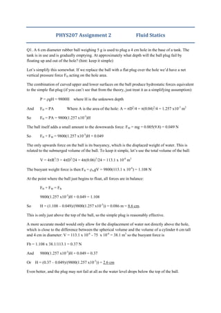
- 1. PHYS207 Assignment 2 Fluid Statics Q1. A 6 cm diameter rubber ball weighing 5 g is used to plug a 4 cm hole in the base of a tank. The tank is in use and is gradually emptying. At approximately what depth will the ball plug fail by floating up and out of the hole? (hint: keep it simple) Let’s simplify this somewhat. If we replace the ball with a flat plug over the hole we’d have a net vertical pressure force FH acting on the hole area. The combination of curved upper and lower surfaces on the ball produce hydrostatic forces equivalent to the simple flat plug (if you can’t see that from the theory, just treat it as a simplifying assumption): P = gH = 9800H where H is the unknown depth And FH = PA Where A is the area of the hole: A = D2 /4 = (0.04)2 /4 = 1.257 x10⁻³ m2 So FH = PA = 9800(1.257 x10⁻³ )H The ball itself adds a small amount to the downwards force: FM = mg = 0.005(9.8) = 0.049 N So FH + FM = 9800(1.257 x10⁻³ )H + 0.049 The only upwards force on the ball is its buoyancy, which is the displaced weight of water. This is related to the submerged volume of the ball. To keep it simple, let’s use the total volume of the ball: V = 4 R3 /3 = 4 D3 /24 = 4 (0.06)3 /24 = 113.1 x 10⁻⁶ m3 The buoyant weight force is then FB = wgV = 9800(113.1 x 10⁻⁶ ) = 1.108 N At the point where the ball just begins to float, all forces are in balance: FH + FM = FB 9800(1.257 x10⁻³ )H + 0.049 = 1.108 So H = (1.108 – 0.049)/(9800(1.257 x10-3 )) = 0.086 m = 8.6 cm. This is only just above the top of the ball, so the simple plug is reasonably effective. A more accurate model would only allow for the displacement of water not directly above the hole, which is close to the difference between the spherical volume and the volume of a cylinder 6 cm tall and 4 cm in diameter: V = 113.1 x 10⁻⁶ - 75 x 10-6 = 38.1 m3 so the buoyant force is Fb = 1.108 x 38.1/113.1 = 0.37 N And 9800(1.257 x10⁻³ )H + 0.049 = 0.37 Or H = (0.37 – 0.049)/(9800(1.257 x10-3 )) = 2.6 cm Even better, and the plug may not fail at all as the water level drops below the top of the ball.
- 2. Q2. Rooms in the lower level of a cruise ship have 30 cm diameter circular windows, or portholes. In rough weather the lower portholes can be momentarily submerged up to 4 m by waves. Determine the instantaneous hydrostatic force in terms of magnitude and position at one of these moments. This can be handled by assuming static and horizontal forces: The mean pressure on the porthole is the pressure at it’s centroid: Assuming the depth is 4 m to the centre of the porthole, we have the working pressure: P = gH = 9800(4) = 39.2 kPa The area of the porthole is A = D2 /4 = (.3)2 /4 = 0.0707 m2 The force is thus F = PA = 39.2(0.0707) = 2.77 kN This acts at the line of the pressure centre, which is located at a depth hp: hp = hc + I/ hcA where hc is the depth to the centroid of the porthole, hc = 4m I = D4 /64 = (0.3)4 /64 = 397.6 x 10⁻⁶ m4 so hp = 4 + 397.6 x 10⁻⁶ /(4(0.0707)) = 4.001 m A hydrostatic force of 2.8 kN is located 1 mm below the centroid of the porthole. Q3. A 2 x 2 m square gate opens clockwise on a horizontal hinge located at point A, which is 100 mm below the centroid of the gate. The gate sits against solid rubber blocks which create an effective pressure seal. The gate is designed to open from the top when the water exceeds a certain depth. To what depth h can the water rise without the gate opening at C? The gate will open as soon as the pressure centre, reflecting the position of the net resultant hydrostatic force, is higher than the hinge at A, since at that point the moment action of the hydrostatic force will have no resistance to opening. The pressure centre is located at: hp = hc + I/ hcA B A C h
- 3. hc is the depth to the centroid of the gate, which we can express as a function of the unknown depth h and the gate dimension CB = 2 m: hc = h – CB/2 = h – 1 We’re told that the hinge is 100 mm below the centroid: hhinge = hc + 0.1 Thus the gate opens when the pressure centre depth equals the hinge depth: hp = hc + I/ hcA = hc + 0.1 or I/ hcA = 0.1 that is I/((h – 1)A) = 0.1 I = bd3 /12 = 2(2)3 /12 = 1.33 m4 A = bd = 4 m2 So I/ ((h – 1)A) = 1.33/(4(h – 1)) = 0.1 Thus h – 1 = 1.33/(4(0.1)) or h = 1.33/0.4 + 1 = 4.33 m Maximum depth h = 4.33 m Q4. Navy divers are called to rescue a group of office workers trapped in a basement under floodwater in Leeds, UK. The only access to the basement is via a 1.5 x 1.5 m horizontal hatch which is currently under 1.8 m of water. The hatch is hinged on one edge, with a solidly built brass ring handle at the other end. The divers try to pull it open, and soon realise they will need a crane. What minimum lifting load should they ask for? What mistake are they making? The pressure on the hatch is: P = gH = 9800(1.8) = 17.6 kPa The pressure force is F = P.A = 17.6 x 10³ (1.5)2 = 39.69 kN This acts from the centre of the hatch to the hinge, an offset of d = 1.5/2 = 0.75 m. This creates a closing moment: Mc = F.d = 39.69x10³ (0.75) = 29.77 kN.m The lifting force on the handle (positioned at the other edge, 1.5 m from the hinge) acts over the full width of the hatch, creating an opening moment. To get the hatch open, the opening moment must equal the closing moment: Mo = Fo(1.5) = 29.77x10³
- 4. Fo = 29.77x10³ /1.5 = 19.85 kN Convert that to mass for purposes of ordering a crane: Crane Lift = 19.85x10³ /9.8 = 2.025 Tonnes. A 2.5 tonne crane should do the job. But will the door handle be able to hold this? Be careful not to drown the workers when you lift the hatch! Q5. A long cylinder of radius 2 m hinged at point A is used as an automatic gate. When the water level reaches 15 m the gate automatically opens. Determine the magnitude of the net hydrostatic moment on the cylinder at the moment the gate opens. What is the mass per unit length of the cylinder? Work this out in horizontal and vertical components: Horizontal: The mean pressure on the rectangular projection of the gate is the pressure at the centroid of the rectangle, at depth hc: hc = 15 – R/2 = 15 – 1 = 14 m Mean horizontal pressure: PH = ghc = 9800(14) = 137.2 kPa The gate is described as “long” and we are not told how long. A useful technique is to express the problem in terms of force per unit length (into the page), so we don’t have to factor in the length – it cancels. The area on which the pressure applies is just the height of the gate multiplied by unit length, that is A per unit length = 2 x 1 = 2.0 m2 /m The horizontal pressure force per unit length of gate is thus: FH = PHA = 137.2(2.0) = 274.4 kN/m Rectangular projection of gate face R = 2m
- 5. This force acts at the pressure centre: hp = hc + I/ hcA Where I = bh3 /12 = h3 /12 and A = bh = h for a unit rectangle I = 23 /12 = 0.67 m4 A = 2 m2 thus hp = hc + I/ hcA = 14 + 0.67/((14)2) = 14.024 m This is a d=1.024 m offset from the hinge, creating a horizontal moment of MH = FH d = 274.4 (1.024) = 281.0 kN.m / m width Vertical: The vertical force on the gate can be visualised as the weight of water missing (displaced) above the curving face of the gate. This is a rectangle with a hemispherical end: Volume per unit width = area A = 13(2) + 22 /4 = 29.14 m3 /m FV = Weight per unit width = A g = 29.14(9800) = 285.6 kN/m This force acts upwards through the combined centroid of the rectangle-hemisphere. Measuring from the centre of the circle, A Ax x i 1 Xp = ((1)26 + (4R/3 )3.14)/29.14 = (26 + 8/3)/29.14 = 0.984 m This is an offset d = 2 – 0.984 = 1.016 m from the hinge This creates a moment per unit width of MV = FV d = 285.6 (1.016) = 290.2 kNm /m The total hydrostatic moment about the hinge is thus MT = MV + MH = 290.2 + 281.0 = 571.2 kNm /m This is balanced by the weight per unit width of the gate acting on the offset of the hinge from the centre of the circle: MT = MgR where M is the mass per unit length of the gate: M = MT/gR = 571.2 x10³ /(9.8(2)) = 29.14 x 10³ kg / m width Q6. A 1.2 m diameter steel pipe carries oil of relative density 0.822 under a head of 70 m of oil. What minimum thickness of 120 MPa (yield stress) steel would be required for a safety factor of 1.5? The safety factor reduces the allowable stress to a level significantly less than the yield stress. The allowable stress in the thin pipe walls is S = 120/1.5 = 80 MPa. Taking a unit length of pipe and considering forces on the cross-section:
- 6. The pressure is worked out from the head and fluid density: P = gH = 822(9.8)70 = 563.9 kPa The pressure force is the pressure times the area of cross-section, Fp = P.D for a unit length: Fp = P.D = 563.9(1.2) = 676.7 kN/m The tensile force in the pipe wall is equal to the tensile stress times the area of the wall: T = S.t. for a unit length. There are two tensile forces to account for as the cross-section has two walls. The two tensile forces thus equal the pressure force: Fp = 2S.t S is the allowable stress, 80 MPa = 80 x106 Pa Thus 676.7 x103 = 2(80 x106 ).t And t = 676.7 x10³ /(2(80 x106 )) = 0.0042 m 4.2 mm is a reasonable thickness for a tensile steel medium pressure tank. As a check, use the longitudinal stress formula given in the study guide: t PD 2 = 563.9x10³ (1.2)/(2(0.0042)) = 80x106 OK D L = 1 t = wall thickness Fp = P.D T = S.t T = S.t