
Recommended
Recommended
More Related Content
What's hot
What's hot (20)
Similar to Chapter 4
Similar to Chapter 4 (20)
Recently uploaded
Recently uploaded (20)
Chapter 4
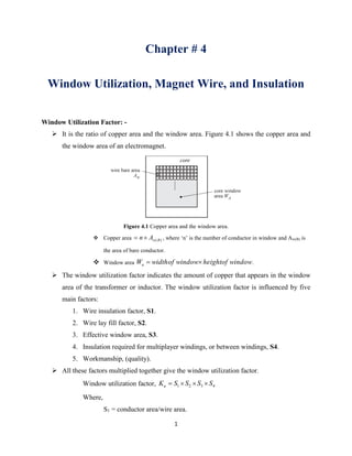
- 1. 1 Chapter # 4 Window Utilization, Magnet Wire, and Insulation Window Utilization Factor: - It is the ratio of copper area and the window area. Figure 4.1 shows the copper area and the window area of an electromagnet. Figure 4.1 Copper area and the window area. Copper area )(BwAn , where ‘n’ is the number of conductor in window and Aw(B) is the area of bare conductor. Window area windowofheightwindowofwidthWa . The window utilization factor indicates the amount of copper that appears in the window area of the transformer or inductor. The window utilization factor is influenced by five main factors: 1. Wire insulation factor, S1. 2. Wire lay fill factor, S2. 3. Effective window area, S3. 4. Insulation required for multiplayer windings, or between windings, S4. 5. Workmanship, (quality). All these factors multiplied together give the window utilization factor. Window utilization factor, 4321 SSSSKu Where, S1 = conductor area/wire area.
- 2. 2 S2 = wound area/usable window area. S3 = usable window area/window area. S4 = usable window area/ (usable window area + insulation). Conductor area, Aw(B) = copper area. Wire area, Aw = copper area + insulation area. Wound area = number of turns x wire area of one turn. Usable window area = available window area - residual area, that results from the particular winding technique used. Window area Wa= available window area. Insulation area = area used for winding insulation. l h Windowarea Windowarea Figure 4.4 Transformer Core of shell type transformer.
- 3. 3 l h Low voltage winding (Awp or Aws) High voltage winding (Aws or Awp) Insulation between windings Bobbin Bobbin Figure 4.5 Cut section view of a shell type transformer. Wire insulation factor (S1): - It is the ratio of bare conductor area (Aw(B)) to the conductor area with insulation (Aw). w Bw A A S )( 1 S1 depends upon both wire size and thickness of insulation coating. Figure 4.2 Comparison of insulation with different wire gauges. AWG stands for American Wire Gauge. SWG stands for Standard Wire Gauge.
- 4. 4 Table 4.1 Wire Gauge chart.
- 5. 5
- 6. 6
- 7. 7
- 8. 8 AWG to mm conversion formula 39/)36( )( 92127.0 n mmnD 0.127 mm is the diameter of 36 AWG copper wire.
- 9. 9 Table 4.2 Dimensional data for insulated copper wire.
- 10. 10 Table 4.2 Raio of bare to insulated conductor for different SWG. S2, Fill Factor S2 is the fill factor is the ratio of wound area/usable window area. Winding Length Winding Build d Unused area for round conductor Figure 4.2 Winding with square conductor and round conductor. For square conductor, fill factor is 1 i.e. 100% For round conductor, fill factor is the ratio between areas of square conductor to that of round conductor. 785.0 4 4 2 2 2 d d S S3, Effective Window (usable window area/window area) The effective window, S3, defines how much of the available window space may actually be used for the winding. The winding area available to the designer depends on the bobbin or tube configuration. Figure 4.3 Transformer windings with margin.
- 11. 11 l h Windowarea Windowarea Figure 4.4 Transformer Core of shell type transformer. l h Low voltage winding (Awp or Aws) High voltage winding (Aws or Awp) Insulation between windings Bobbin Bobbin Figure 4.5 Cut section view of a shell type transformer.
- 12. 12 Table 4.3 Winding margin and Layer insulation thickness. S4, Insulation Factor (usable window area/(usable window area + insulation)). The insulation factor, S4, defines how much of the usable window space is actually being used for insulation. Summary: - Window utilization factor is 4321 SSSSKu . A good approximation for the window utilization factor is Ku = 0.4. For which S1 = conductor area/wire area = 0.855, #20 AWG. S2 = wound area/usable window area = 0.61. S3 = usable window area/window area = 0.75. S4 = usable window area/(usable window area + insulation)1. 391.0175.061.0855.04321 SSSSKu .