Pressure Regulating Valve - Type G-4 Cash Valve
•
0 likes•515 views

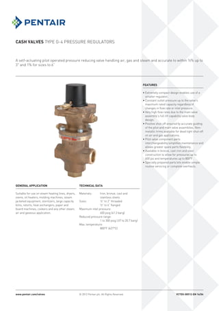
A self-actuating pilot operated pressure reducing valve handling air, gas and steam and accurate to within ½% up to 3" and 1% for sizes to 6” Suitable for use on steam heating lines, dryers, ovens, oil heaters, molding machines, steam jacketed equipment, sterilizers, large capacity kilns, retorts, heat exchangers, paper and board machines, cookers and any other steam, air and gaseous application.

Recommended
Recommended
More Related Content
What's hot
What's hot (18)
Viewers also liked
Viewers also liked (10)
Similar to Pressure Regulating Valve - Type G-4 Cash Valve
Similar to Pressure Regulating Valve - Type G-4 Cash Valve (20)
More from Classic Controls, Inc.
More from Classic Controls, Inc. (20)
Recently uploaded
Recently uploaded (20)
Pressure Regulating Valve - Type G-4 Cash Valve
- 1. CASH VALVES TYPE G-4 PRESSURE REGULATORS A self-actuating pilot operated pressure reducing valve handling air, gas and steam and accurate to within ½% up to 3" and 1% for sizes to 6” www.pentair.com/valves © 2012 Pentair plc. All Rights Reserved. VCTDS-00512-EN 16/04 FEATURES • Extremely compact design enables use of a smaller regulator. • Constant outlet pressure up to the valve’s maximum rated capacity regardless of changes in flow rate or inlet pressure. • Very high flow rates due to the main valve assembly’s full lift capability valve body design. • Positive shut-off ensured by accurate guiding of the pilot and main valve assemblies. Non- metallic trims available for dead tight shut-off on air and gas applications. • Pilot valve component parts interchangeability simplifies maintenance and allows greater spare parts flexibility. • Available in bronze, cast iron and steel construction to allow for pressures up to 600 psi and temperatures up to 800°F. • Specially prepared parts kits enable simple routine servicing or complete overhauls. TECHNICAL DATA Materials: Iron, bronze, cast and stainless steels Sizes: ½” to 2” threaded ½” to 6” flanged Maximum inlet pressure: 600 psig (41.3 barg) Reduced pressure range: 1 to 300 psig (.07 to 20.7 barg) Max. temperature: 800°F (427°C) GENERAL APPLICATION Suitable for use on steam heating lines, dryers, ovens, oil heaters, molding machines, steam jacketed equipment, sterilizers, large capacity kilns, retorts, heat exchangers, paper and board machines, cookers and any other steam, air and gaseous application.
- 2. 2 CASH VALVES TYPE G-4 PRESSURE REGULATORS Fig. 2042 - Bronze Fig. 2043 - Bronze Fig. 2044 - Cast iron Fig. 2046 - Cast steel *Note: 1 to 5 psig reduced pressure available with low pressure top maximum inlet pressure 100 psig • (½”) and (¾”) sizes restricted internals in 1” body. • (1 ¼”) and (1½”) sizes restricted internals in 2” body. PRESSURE TEMPERATURE RATINGS Material End connection Pressure (psig) Description ASTM spec. ANSI Class 0 to 150F 250F 300F 400F 450F 500F 750F Cast Iron A126 Class B CL125 (iron) 200 175 160 135 125 - - Bronze B62 Alloy 836 CL150 (bronze) 225 195 180 150 - - - CL300 (bronze) 500 425 390 300 - - - CL250 (bronze threaded) 400 365 300 250 - - - Carbon steel A216 GR WCB CL150 (steel) 285 245 230 195 185 170 * A351 CF8 (304) CL300 (steel) 740 660 655 630 615 590 500 CL250 (steel threaded) 600 530 525 500 490 470 460 * 570°F for 150 psig Valve size Inlet press. range (psig) Minimum press. differential (psig) ½”-2” 10-50 5 50-120 10 120 PLUS 15 2½”-4” 10-50 10 50 PLUS 15 5”-6” Refer to sales office Refer to sales office Description Size range ins ½ ¾ 1 1¼ 1½ 2 ½ ¾ 1 1¼ 1½ 2 2½ 3 4 5 6 ½ ¾ 1 1¼ 1½ 2 2½ 3 4 5 6 Maximum inlet press/temp ratings Pressure/temperature ratings are strictly in accordance with the table below Reduced pressure range psig 5*-300 5*-300 5*-235 air and gases 5*-175 steam 5-175 5-300 5-175 Flanges ANSI NPTF CL150 and CL300 per ANSI B16.24 CL125 per ANSI B16.1 CL150 and CL300 per ANSI B16.5 MINIMUM PRESSURE DIFFERENTIAL The pressure differential is the difference between the inlet pressure and outlet (reduced) pressure. The minimum allowable pressure differential varies depending upon both the inlet pressure and the size of the valves.
- 3. 3 A B C D E F G H I J K L CASH VALVES TYPE G-4 PRESSURE REGULATORS OPERATION The G-4 regulator is primarily designed for use on steam although it works equally well with air and gases. It will maintain a constant pressure irrespective of variations in inlet pressure or steam demand from the system. Steam at inlet pressure passes through the inlet relay port (G) to the pilot valve (D). Both pilot and main valves (H) initially are closed by the action of the pilot and main valve springs (E and I). The pilot valve is opened by clockwise rotation of the adjusting screw (A) which compresses the adjusting spring (B) and applies load to the topside of the diaphragm (C), pushing open the pilot valve. Steam at inlet pressure now passes through the pilot valve and a relay port (K) to the piston (F), which pushes open the main valve. The inlet steam pressure is reduced as it passes through the open main valve and seat to the valve outlet. At the same time steam at outlet pressure passes up the relay port (L) to the underside of the diaphragm. The opening of the main valve determines the outlet pressure and this, in turn, is controlled by the pilot valve. The outlet pressure is a result of balancing the action of the adjusting spring on the top of the diaphragm against the reduced pressure acting on the underside, thus controlling the opening of the pilot valve. The sensitivity of the diaphragm and adjusting spring ensure that any variation in reduced pressure will cause the pilot valve to open or close sufficiently to move the piston and main valve between the fully open and closed positions. In this way, the outlet pressure is maintained accurately under all operating conditions. Outlet pressure is increased by clockwise rotation of the adjusting screw or decreased by counter-clockwise rotation. Typical installation Inlet Outlet A. Adjusting screw B. Adjusting spring C. Diaphragm D. Pilot valve E. Pilot valve spring F. Piston G. Inlet relay port H. Main valve I. Main valve spring J. Remote control port K. Piston relay port L. Reduced pressure relay port Inlet strainer Inlet pipe Inlet pressure gauge Dirt pocket and steam trap Bypass valve globe type Needle valve Safety valve Outlet pipe Outlet pressure gauge Shut-off valve Remote sensing connection Not less than 6’ Type G-4 SECTION VIEW
- 4. 4 33 25 29 27 31 7 8 1 4 21 3 2 6 5 26 C B A 49 Specifications CASH VALVES TYPE G-4 PRESSURE REGULATORS DIMENSIONS Fig. 2042 Fig. 2043 Size ½ ¾ 1 1¼ 1½ 2 ½ ¾ 1 1¼ 1½ 2 A 4⅛ 4⅛ 4½ 4⅞ 5¼ 6⅜ 5½ 5⅝ 6¾ 7 7½ 8½ B 8 8¼ 8⅜ 9⅝ 9⅞ 10¼ 8 8¼ 8⅜ 9⅝ 9⅞ 10¼ C 2⅜ 2½ 2⅝ 3 3⅛ 3¼ 2⅜ 2½ 2⅝ 3 3⅛ 3¼ Wt.lb. 13.2 15.0 15.4 23.8 28.0 33.9 17.6 18.9 19.8 30.0 35.9 45.8 Fig. 2044 Fig. 2046 Size 2½ 3 4 5 6 1 2 2½ 3 4 5 6 A 10 11¼ 13½ 16 16½ 6¾ 9 10 11¼ 13½ 16 16½ B 11¾ 12 13⅜ 16¾ 17⅝ 8¾ 10½ 11¼ 11¼ 12¾ 15¾ 16½ C 5¼ 5¾ 6⅞ 9 9¾ 2¾ 3½ 5⅛ 5¾ 7 8⅝ 9¾ Wt.lb. 77.0 104.0 174.0 247.0 351.0 30.0 58.0 93.0 115.0 192.0 273.0 381.0 STANDARD ASSEMBLY REMOTE CONTROL *NOTE We recommend a remote sensing connection be fitted whenever: 1. The outlet pressure is below 55% of the inlet pressure. 2. A low pressure top assembly is fitted. 3. Difficult outlet pipework conditions occur. Please refer to factory for more details. *See note *See note LOW PRESSURE TOP ASSEMBLY A special low pressure top assembly should be fitted for outlet pressures from 1 up to 5 psig (0.07 to 0.3 barg). Low pressure tops are available for valves up to 4” (100 mm) size. Larger valves are not suitable for outlet pressures of less than 5 psig (0.3 barg). The low pressure top is supplied as a complete conversion unit for fitting to the existing pilot valve assembly. It incorporates a large diaphragm, providing a greater effective area and improved sensitivity to very low outlet pressure conditions.
- 5. 5 CASH VALVES TYPE G-4 PRESSURE REGULATORS MATERIALS OF CONSTRUCTION Part no. Part Figure 2042 and 2043 Figure 2044 Figure 2046 1 Body Bronze Cast iron Cast steel 2 Main valve* Stainless steel Stainless steel Stainless steel 3 Main valve seat Stainless steel Stainless steel Stainless steel 4 Bottom plug cover Manganese bronze Cast iron/aluminum bronze Stainless steel 5 Piston Brass Bronze Steel 6 Piston rings Phosphor bronze Phosphor bronze Chrome iron 7 Liner Stainless steel Stainless steel Stainless steel 8 Piston guide Stainless steel Stainless steel Stainless steel (6” Monel® ) 21 Main valve spring Stainless steel Stainless steel Stainless steel 25 Pilot valve top Bronze Bronze Steel 26 Pilot valve* Stainless steel Stainless steel Stainless steel 27 Pilot valve plug Stainless steel Stainless steel Stainless steel 29 Diaphragm Stainless steel Stainless steel Stainless steel 31 Pilot valve spring Stainless steel Stainless steel Stainless steel 33 Adjusting spring Steel Steel Steel 49 Diaphragm for low pressure top Phosphor bronze Phosphor bronze N/A Gaskets: Steam-non-asbestos material. Air and gases-PTFE (2” and below) rubber bonded cork (2½” and above). *Main and pilot valves are fitted with elastomeric inserts for use on air and gases when tight shut-off is required. Note: for full parts list please refer to installation and maintenance instructions available on request. TRIM SELECTION Duty Trim Standard valve Steam Stainless steel Standard valve Compressed air, carbon dioxide, nitrogen, hydrogen, helium Nitrile Oxygen Fig. 2043/3 only Oxygen, methane FKM VALVE SIZE ½” - 4” 5” and 6”* 1 - 5 5 - 20 5 - 50 (Yellow) 10 - 50 10 - 100 (Black) 40 - 100 40 - 150 (White) 50 -175 50 - 200 (Green) 100 - 300 (Red) *Not color coded Specifications SPRINGS NOTE It is advisable to select a spring which will ensure that there is at least 10% extra adjustment available above the required reduced set pressure. The spring with the lowest pressure range should be used whenever possible.
- 6. 6 25 20 122 249 410 625 904 1555 - - - - - 15 142 290 478 728 1053 1810 2903 3620 6940 9393 13379 5 151 308 507 773 1118 1921 3082 3843 6889 9971 14202 50 45 160 327 540 823 1189 2044 - - - - - 25 254 518 853 1300 1880 3231 5183 6463 11586 16769 23884 5 254 518 853 1300 1880 3231 5183 6463 11586 16769 23884 75 65 240 490 807 1230 1778 3057 - - - - - 60 274 560 923 1407 2034 3496 5401 6735 12073 17474 24887 40 351 717 1182 1801 2603 4475 7178 8951 16045 23223 33076 5 351 717 1182 1801 2603 4475 7178 8951 16045 23223 33076 100 90 275 562 926 1411 2039 3505 - - - - - 85 318 650 1071 1632 2360 4056 5984 7463 13377 19362 27576 55 453 924 1522 2319 3352 5762 9241 11524 20657 29899 42583 5 453 924 1522 2319 3352 5762 9241 11524 20657 29899 42583 125 110 356 728 1199 1827 2641 4540 6486 8088 14499 20985 29888 65 555 1133 1866 2844 4111 7067 11334 14134 25334 36668 52225 10 555 1133 1866 2844 4111 7067 11334 14134 25334 36668 52225 5 555 1133 1866 2844 4111 7067 11334 14134 25334 - - 150 135 391 798 1315 2004 2897 4980 6850 8543 15313 22164 31568 80 659 1344 2215 3375 4878 8385 13448 16771 30061 43509 61968 10 659 1344 2215 3375 4878 8385 13448 16771 30061 43509 61968 5 659 1344 2215 3375 4878 8385 13448 16771 30061 - - 200 185 440 898 1479 2254 3258 5600 7096 8850 15863 - - 175 550 1122 1848 2816 4071 6998 10044 12525 22451 33150 47200 110 852 1738 2863 4363 6306 10841 17386 21682 38864 56250 80114 40 852 1738 2863 4363 6306 10841 17386 21682 38864 56250 80114 250 235 492 1003 1653 2519 3641 6260 7378 9200 16492 - - 175 941 1920 3162 4818 6964 11972 19200 23944 42918 62420 88913 135 1054 2151 3544 5401 7806 13418 21519 26836 48103 69622 99159 100 1054 2151 3544 5401 7806 13418 21519 26836 48103 69622 99159 55 1054 2151 3544 5401 7806 13418 21519 26836 48103 69622 99159 300 285 542 1105 1821 2775 4011 6895 7619 9501 17030 - - 175 904 2527 4163 6344 9170 15762 25279 31525 56507 81935 116696 165 1255 2560 4218 6427 9289 15968 25609 31936 57244 82854 118004 100 1255 2560 4218 6427 9289 15968 25609 31936 57244 82854 118004 75 1255 2560 4218 6427 9289 15968 25609 31936 57244 82854 118004 Specifications - capacities CASH VALVES TYPE G-4 PRESSURE REGULATORS Steam - pounds per hour Inlet pressure Outlet pressure ½ ¾ 1 1¼ 1½ 2 2½ 3 4 5 6 Flow coefficient (Cv) 2.1 4.3 7.1 10.7 15.6 26.8 42.9 53.4 95.6 138.7 197.5 These capacities are based on a 3% variance from the regulator’s set point.
- 7. 7 25 20 38 79 130 199 288 495 - - - - - 15 45 93 153 234 338 582 934 1165 2088 3022 4304 5 48 99 163 249 360 620 994 1240 2224 3218 4584 50 45 49 100 165 251 363 625 - - - - - 25 80 164 271 413 597 1026 1646 2053 3680 5326 7586 5 80 164 271 413 597 1026 1646 2053 3680 5326 7586 75 65 73 150 247 377 544 936 - - - - - 60 85 174 286 436 631 1085 1670 2083 3733 5404 7696 40 111 227 374 570 823 1416 2271 2832 5077 7349 10466 5 111 227 374 570 823 1416 2271 2832 5077 7349 10466 100 90 82 168 276 421 609 1047 - - - - - 85 96 197 325 496 717 1283 1802 2247 4028 5831 8305 55 142 289 477 727 1050 1806 2897 3612 6475 9372 13349 5 142 289 477 727 1050 1806 2897 3612 6475 9372 13349 125 110 108 220 363 553 799 1374 1894 2412 4225 6260 8915 65 175 357 589 897 1297 2229 3576 4459 7994 11570 16479 10 175 357 589 897 1297 2229 3576 4459 7994 11570 16479 5 175 357 589 897 1297 2229 3576 4459 7994 - - 150 135 116 237 390 595 861 1480 1936 2442 4412 6441 9174 80 206 421 693 1056 1527 2625 4210 5250 9411 13622 19401 10 206 421 693 1056 1527 2625 4210 5250 9411 13622 19401 5 206 421 693 1056 1527 2625 4210 5250 9411 - - 200 185 128 262 432 659 952 1637 1987 2478 4443 - - 175 166 338 557 850 1228 2111 2987 3725 6677 9877 14082 110 268 547 901 1374 1986 3414 5476 6829 12241 17717 25234 40 268 547 901 1374 1986 3414 5476 6829 12241 17717 25234 250 235 190 286 472 720 1040 1788 2030 2546 4480 - - 175 292 596 928 1496 2163 3718 5963 7437 13330 19390 27620 135 330 674 1111 1693 2447 4207 6747 8414 15082 21829 31091 100 330 674 1111 1693 2447 4207 6747 8414 15082 21829 31091 55 330 674 1111 1693 2447 4207 6747 8414 15082 21829 31091 300 285 152 310 511 757 1126 1901 2075 2600 4502 - - 175 387 790 1301 1983 2867 4928 7904 9857 17668 25623 36494 165 392 801 1320 2011 2907 4998 8015 9996 17917 25993 36935 100 392 801 1320 2011 2907 4998 8015 9996 17917 25993 36935 75 392 801 1320 2011 2907 4998 8015 9996 17917 25993 36935 CASH VALVES TYPE G-4 PRESSURE REGULATORS Specifications - capacities Type G-4 air (SCFM) capacity information Inlet pressure Outlet pressure ½ ¾ 1 1¼ 1½ 2 2½ 3 4 5 6 Flow coefficient (Cv) 2.1 4.3 7.1 10.7 15.6 26.8 42.9 53.4 95.6 138.7 197.5 These capacities are based on a 3% variance from the regulator’s set point. Gas Oxygen Nitrogen Hydrogen Helium CO2 Argon Methane Factor 1.05 0.98 0.26 0.37 1.24 1.18 0.74 To find valve capacities for gases at ambient temperatures multiply required flow rate by Approximate factor. Use chart above for valve capacity.
- 8. 8 CASH VALVES TYPE G-4 PRESSURE REGULATORS PENTAIR VALVES & CONTROLS www.pentair.com/valves All Pentair trademarks and logos are owned by Pentair plc. All other brand or product names are trademarks or registered marks of their respective owners. Because we are continuously improving our products and services, Pentair reserves the right to change product designs and specifications without notice. Pentair is an equal opportunity employer. © 2015 Pentair plc. All rights reserved. HOW TO ORDER Specify Cash Valve type G-4 and state: 1. Pipe size 2. End connections 3. Inlet pressure 4. Outlet pressure range and setting 5. Maximum flow rate desired 6. Service 7. Trim 8. Body material 9. Operating temperature 10. For remote sensing: order remote control adapter NOTE NPTF, also referred to as 'Dryseal' thread, is designed to provide a more leak-free seal without the use of PTFE tape or other sealant compound. NPTF threads are interchangeable with NPT threads and are standard on all Cash Valve products.