Sachpazis_Pocket reinforced masonry retaining wall analysis exampleEN1997-1-2004
•
0 likes•843 views

Pocket reinforced masonry Retaining Wall Analysis & Design, In accordance with EN1997-1:2004 incorporating Corrigendum dated February 2009 and the recommended values

Recommended
Recommended
More Related Content
What's hot
What's hot (20)
Similar to Sachpazis_Pocket reinforced masonry retaining wall analysis exampleEN1997-1-2004
Similar to Sachpazis_Pocket reinforced masonry retaining wall analysis exampleEN1997-1-2004 (17)
More from Dr.Costas Sachpazis
More from Dr.Costas Sachpazis (20)
Recently uploaded
Recently uploaded (20)
Sachpazis_Pocket reinforced masonry retaining wall analysis exampleEN1997-1-2004
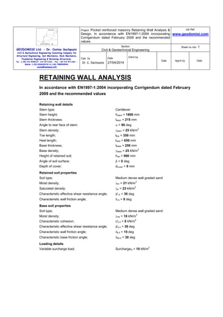
- 1. GEODOMISI Ltd. - Dr. Costas Sachpazis Civil & Geotechnical Engineering Consulting Company for Structural Engineering, Soil Mechanics, Rock Mechanics, Foundation Engineering & Retaining Structures. Tel.: (+30) 210 5238127, 210 5711263 - Fax.:+30 210 5711461 - Mobile: (+30) 6936425722 & (+44) 7585939944, costas@sachpazis.info Project: Pocket reinforced masonry Retaining Wall Analysis & Design, In accordance with EN1997-1:2004 incorporating Corrigendum dated February 2009 and the recommended values. Job Ref. www.geodomisi.com Section Civil & Geotechnical Engineering Sheet no./rev. 1 Calc. by Dr. C. Sachpazis Date 27/04/2014 Chk'd by Date App'd by Date RETAINING WALL ANALYSIS In accordance with EN1997-1:2004 incorporating Corrigendum dated February 2009 and the recommended values Retaining wall details Stem type; Cantilever Stem height; hstem = 1800 mm Stem thickness; tstem = 215 mm Angle to rear face of stem; α = 90 deg Stem density; γstem = 25 kN/m 3 Toe length; ltoe = 350 mm Heel length; lheel = 650 mm Base thickness; tbase = 250 mm Base density; γbase = 25 kN/m 3 Height of retained soil; hret = 900 mm Angle of soil surface; β = 0 deg Depth of cover; dcover = 0 mm Retained soil properties Soil type; Medium dense well graded sand Moist density; γmr = 21 kN/m 3 Saturated density; γsr = 23 kN/m 3 Characteristic effective shear resistance angle; φ'r.k = 30 deg Characteristic wall friction angle; δr.k = 0 deg Base soil properties Soil type; Medium dense well graded sand Moist density; γmb = 18 kN/m 3 Characteristic cohesion; c'b.k = 0 kN/m 2 Characteristic effective shear resistance angle; φ'b.k = 30 deg Characteristic wall friction angle; δb.k = 15 deg Characteristic base friction angle; δbb.k = 30 deg Loading details Variable surcharge load; SurchargeQ = 10 kN/m 2
- 2. GEODOMISI Ltd. - Dr. Costas Sachpazis Civil & Geotechnical Engineering Consulting Company for Structural Engineering, Soil Mechanics, Rock Mechanics, Foundation Engineering & Retaining Structures. Tel.: (+30) 210 5238127, 210 5711263 - Fax.:+30 210 5711461 - Mobile: (+30) 6936425722 & (+44) 7585939944, costas@sachpazis.info Project: Pocket reinforced masonry Retaining Wall Analysis & Design, In accordance with EN1997-1:2004 incorporating Corrigendum dated February 2009 and the recommended values. Job Ref. www.geodomisi.com Section Civil & Geotechnical Engineering Sheet no./rev. 1 Calc. by Dr. C. Sachpazis Date 27/04/2014 Chk'd by Date App'd by Date Calculate retaining wall geometry Base length; lbase = ltoe + tstem + lheel = 1215 mm Moist soil height; hmoist = hsoil = 900 mm Length of surcharge load; lsur = lheel = 650 mm - Distance to vertical component; xsur_v = lbase - lheel / 2 = 890 mm 2501800 900900 1150
- 3. GEODOMISI Ltd. - Dr. Costas Sachpazis Civil & Geotechnical Engineering Consulting Company for Structural Engineering, Soil Mechanics, Rock Mechanics, Foundation Engineering & Retaining Structures. Tel.: (+30) 210 5238127, 210 5711263 - Fax.:+30 210 5711461 - Mobile: (+30) 6936425722 & (+44) 7585939944, costas@sachpazis.info Project: Pocket reinforced masonry Retaining Wall Analysis & Design, In accordance with EN1997-1:2004 incorporating Corrigendum dated February 2009 and the recommended values. Job Ref. www.geodomisi.com Section Civil & Geotechnical Engineering Sheet no./rev. 1 Calc. by Dr. C. Sachpazis Date 27/04/2014 Chk'd by Date App'd by Date Effective height of wall; heff = hbase + dcover + hret = 1150 mm - Distance to horizontal component; xsur_h = heff / 2 = 575 mm Area of wall stem; Astem = hstem × tstem = 0.387 m 2 - Distance to vertical component; xstem = ltoe + tstem / 2 = 457 mm Area of wall base; Abase = lbase × tbase = 0.304 m 2 - Distance to vertical component; xbase = lbase / 2 = 607 mm Area of moist soil; Amoist = hmoist × lheel = 0.585 m 2 - Distance to vertical component; xmoist_v = lbase - (hmoist × lheel 2 / 2) / Amoist = 890 mm - Distance to horizontal component; xmoist_h = heff / 3 = 383 mm Partial factors on actions - Table A.3 - Combination 1 Permanent unfavourable action; γG = 1.35 Permanent favourable action; γGf = 1.00 Variable unfavourable action; γQ = 1.50 Variable favourable action; γQf = 0.00 Partial factors for soil parameters – Table A.4 - Combination 1 Angle of shearing resistance; γφ' = 1.00 Effective cohesion; γc' = 1.00 Weight density; γγ = 1.00 Retained soil properties Design effective shear resistance angle; φ'r.d = atan(tan(φ'r.k) / γφ') = 30 deg Design wall friction angle; δr.d = atan(tan(δr.k) / γφ') = 0 deg Base soil properties Design effective shear resistance angle; φ'b.d = atan(tan(φ'b.k) / γφ') = 30 deg Design wall friction angle; δb.d = atan(tan(δb.k) / γφ') = 15 deg Design base friction angle; δbb.d = atan(tan(δbb.k) / γφ') = 30 deg Design effective cohesion; c'b.d = c'b.k / γc' = 0 kN/m 2 Using Coulomb theory Active pressure coefficient; KA = sin(α + φ'r.d) 2 / (sin(α) 2 × sin(α - δr.d) × [1 + √[sin(φ'r.d + δr.d) × sin(φ'r.d - β) / (sin(α - δr.d) × sin(α + β))]] 2 ) = 0.333 Passive pressure coefficient; KP = sin(90 - φ'b.d) 2 / (sin(90 + δb.d) × [1 - √[sin(φ'b.d + δb.d) × sin(φ'b.d) / (sin(90 + δb.d))]] 2 ) = 4.977 Sliding check Vertical forces on wall Wall stem; Fstem = γGf × Astem × γstem = 9.7 kN/m Wall base; Fbase = γGf × Abase × γbase = 7.6 kN/m Moist retained soil; Fmoist_v = γGf × Amoist × γmr = 12.3 kN/m
- 4. GEODOMISI Ltd. - Dr. Costas Sachpazis Civil & Geotechnical Engineering Consulting Company for Structural Engineering, Soil Mechanics, Rock Mechanics, Foundation Engineering & Retaining Structures. Tel.: (+30) 210 5238127, 210 5711263 - Fax.:+30 210 5711461 - Mobile: (+30) 6936425722 & (+44) 7585939944, costas@sachpazis.info Project: Pocket reinforced masonry Retaining Wall Analysis & Design, In accordance with EN1997-1:2004 incorporating Corrigendum dated February 2009 and the recommended values. Job Ref. www.geodomisi.com Section Civil & Geotechnical Engineering Sheet no./rev. 1 Calc. by Dr. C. Sachpazis Date 27/04/2014 Chk'd by Date App'd by Date Total; Ftotal_v = Fstem + Fbase + Fmoist_v = 29.6 kN/m Horizontal forces on wall Surcharge load; Fsur_h = KA × γQ × SurchargeQ × heff = 5.8 kN/m Moist retained soil; Fmoist_h = γG × KA × γmr × heff 2 / 2 = 6.2 kN/m Total; Ftotal_h = Fmoist_h + Fsur_h = 12 kN/m Check stability against sliding Base soil resistance; Fexc_h = γGf × KP × cos(δb.d) × γmb × (hpass + hbase) 2 / 2 = 2.7 kN/m Base friction; Ffriction = Ftotal_v × tan(δbb.d) = 17.1 kN/m Resistance to sliding; Frest = Fexc_h + Ffriction = 19.8 kN/m Factor of safety; FoSsl = Frest / Ftotal_h = 1.647 PASS - Resistance to sliding is greater than sliding force Overturning check Vertical forces on wall Wall stem; Fstem = γGf × Astem × γstem = 9.7 kN/m Wall base; Fbase = γGf × Abase × γbase = 7.6 kN/m Moist retained soil; Fmoist_v = γGf × Amoist × γmr = 12.3 kN/m Total; Ftotal_v = Fstem + Fbase + Fmoist_v = 29.6 kN/m Horizontal forces on wall Surcharge load; Fsur_h = KA × γQ × SurchargeQ × heff = 5.8 kN/m Moist retained soil; Fmoist_h = γG × KA × γmr × heff 2 / 2 = 6.2 kN/m Base soil; Fexc_h = -γGf × KP × cos(δb.d) × γmb × (hpass + hbase) 2 / 2 = -2.7 kN/m Total; Ftotal_h = Fmoist_h + Fexc_h + Fsur_h = 9.3 kN/m Overturning moments on wall Surcharge load; Msur_OT = Fsur_h × xsur_h = 3.3 kNm/m Moist retained soil; Mmoist_OT = Fmoist_h × xmoist_h = 2.4 kNm/m Total; Mtotal_OT = Mmoist_OT + Msur_OT = 5.7 kNm/m Restoring moments on wall Wall stem; Mstem_R = Fstem × xstem = 4.4 kNm/m Wall base; Mbase_R = Fbase × xbase = 4.6 kNm/m Moist retained soil; Mmoist_R = Fmoist_v × xmoist_v = 10.9 kNm/m Base soil; Mexc_R = -Fexc_h × xexc_h = 0.2 kNm/m Total; Mtotal_R = Mstem_R + Mbase_R + Mmoist_R + Mexc_R = 20.2 kNm/m Check stability against overturning Factor of safety; FoSot = Mtotal_R / Mtotal_OT = 3.543
- 5. GEODOMISI Ltd. - Dr. Costas Sachpazis Civil & Geotechnical Engineering Consulting Company for Structural Engineering, Soil Mechanics, Rock Mechanics, Foundation Engineering & Retaining Structures. Tel.: (+30) 210 5238127, 210 5711263 - Fax.:+30 210 5711461 - Mobile: (+30) 6936425722 & (+44) 7585939944, costas@sachpazis.info Project: Pocket reinforced masonry Retaining Wall Analysis & Design, In accordance with EN1997-1:2004 incorporating Corrigendum dated February 2009 and the recommended values. Job Ref. www.geodomisi.com Section Civil & Geotechnical Engineering Sheet no./rev. 1 Calc. by Dr. C. Sachpazis Date 27/04/2014 Chk'd by Date App'd by Date PASS - Maximum restoring moment is greater than overturning moment Bearing pressure check Vertical forces on wall Wall stem; Fstem = γG × Astem × γstem = 13.1 kN/m Wall base; Fbase = γG × Abase × γbase = 10.3 kN/m Surcharge load; Fsur_v = γQ × SurchargeQ × lheel = 9.8 kN/m Moist retained soil; Fmoist_v = γG × Amoist × γmr = 16.6 kN/m Total; Ftotal_v = Fstem + Fbase + Fmoist_v + Fsur_v = 49.6 kN/m Horizontal forces on wall Surcharge load; Fsur_h = KA × γQ × SurchargeQ × heff = 5.8 kN/m Moist retained soil; Fmoist_h = γG × KA × γmr × heff 2 / 2 = 6.2 kN/m Total; Ftotal_h = max(Fmoist_h + Fpass_h + Fsur_h - Ftotal_v × tan(δbb.d), 0 kN/m) = 0 kN/m Moments on wall Wall stem; Mstem = Fstem × xstem = 6 kNm/m Wall base; Mbase = Fbase × xbase = 6.2 kNm/m Surcharge load; Msur = Fsur_v × xsur_v - Fsur_h × xsur_h = 5.4 kNm/m Moist retained soil; Mmoist = Fmoist_v × xmoist_v - Fmoist_h × xmoist_h = 12.4 kNm/m Total; Mtotal = Mstem + Mbase + Mmoist + Msur = 29.9 kNm/m Check bearing pressure Distance to reaction; x = Mtotal / Ftotal_v = 603 mm Eccentricity of reaction; e = x - lbase / 2 = -4 mm Loaded length of base; lload = 2 × x = 1206 mm Bearing pressure at toe; qtoe = Ftotal_v / lload = 41.2 kN/m 2 Bearing pressure at heel; qheel = 0 kN/m 2 Effective overburden pressure; q = (tbase + dcover) × γmb = 4.5 kN/m 2 Design effective overburden pressure; q' = q / γγ = 4.5 kN/m 2 Bearing resistance factors; Nq = Exp(π × tan(φ'b.d)) × (tan(45 deg + φ'b.d / 2)) 2 = 18.401 Nc = (Nq - 1) × cot(φ'b.d) = 30.14 Nγ = 2 × (Nq - 1) × tan(φ'b.d) = 20.093 Foundation shape factors; sq = 1 sγ = 1 sc = 1 Load inclination factors; H = Ftotal_h = 0 kN/m V = Ftotal_v = 49.6 kN/m m = 2
- 6. GEODOMISI Ltd. - Dr. Costas Sachpazis Civil & Geotechnical Engineering Consulting Company for Structural Engineering, Soil Mechanics, Rock Mechanics, Foundation Engineering & Retaining Structures. Tel.: (+30) 210 5238127, 210 5711263 - Fax.:+30 210 5711461 - Mobile: (+30) 6936425722 & (+44) 7585939944, costas@sachpazis.info Project: Pocket reinforced masonry Retaining Wall Analysis & Design, In accordance with EN1997-1:2004 incorporating Corrigendum dated February 2009 and the recommended values. Job Ref. www.geodomisi.com Section Civil & Geotechnical Engineering Sheet no./rev. 1 Calc. by Dr. C. Sachpazis Date 27/04/2014 Chk'd by Date App'd by Date iq = [1 - H / (V + lload × c'b.d × cot(φ'b.d))] m = 1 iγ = [1 - H / (V + lload × c'b.d × cot(φ'b.d))] (m + 1) = 1 ic = iq - (1 - iq) / (Nc × tan(φ'b.d)) = 1 Net ultimate bearing capacity; nf = c'b.d × Nc × sc × ic + q' × Nq × sq × iq + 0.5 × γmb × lload × Nγ × sγ × iγ = 300.9 kN/m 2 Factor of safety; FoSbp = nf / max(qtoe, qheel) = 7.31 PASS - Allowable bearing pressure exceeds maximum applied bearing pressure Partial factors on actions - Table A.3 - Combination 2 Permanent unfavourable action; γG = 1.00 Permanent favourable action; γGf = 1.00 Variable unfavourable action; γQ = 1.30 Variable favourable action; γQf = 0.00 Partial factors for soil parameters – Table A.4 - Combination 2 Angle of shearing resistance; γφ' = 1.25 Effective cohesion; γc' = 1.25 Weight density; γγ = 1.00 Retained soil properties Design effective shear resistance angle; φ'r.d = atan(tan(φ'r.k) / γφ') = 24.8 deg Design wall friction angle; δr.d = atan(tan(δr.k) / γφ') = 0 deg Base soil properties Design effective shear resistance angle; φ'b.d = atan(tan(φ'b.k) / γφ') = 24.8 deg Design wall friction angle; δb.d = atan(tan(δb.k) / γφ') = 12.1 deg Design base friction angle; δbb.d = atan(tan(δbb.k) / γφ') = 24.8 deg Design effective cohesion; c'b.d = c'b.k / γc' = 0 kN/m 2 Using Coulomb theory Active pressure coefficient; KA = sin(α + φ'r.d) 2 / (sin(α) 2 × sin(α - δr.d) × [1 + √[sin(φ'r.d + δr.d) × sin(φ'r.d - β) / (sin(α - δr.d) × sin(α + β))]] 2 ) = 0.409 Passive pressure coefficient; KP = sin(90 - φ'b.d) 2 / (sin(90 + δb.d) × [1 - √[sin(φ'b.d + δb.d) × sin(φ'b.d) / (sin(90 + δb.d))]] 2 ) = 3.473 Sliding check Vertical forces on wall Wall stem; Fstem = γGf × Astem × γstem = 9.7 kN/m Wall base; Fbase = γGf × Abase × γbase = 7.6 kN/m Moist retained soil; Fmoist_v = γGf × Amoist × γmr = 12.3 kN/m Total; Ftotal_v = Fstem + Fbase + Fmoist_v = 29.6 kN/m
- 7. GEODOMISI Ltd. - Dr. Costas Sachpazis Civil & Geotechnical Engineering Consulting Company for Structural Engineering, Soil Mechanics, Rock Mechanics, Foundation Engineering & Retaining Structures. Tel.: (+30) 210 5238127, 210 5711263 - Fax.:+30 210 5711461 - Mobile: (+30) 6936425722 & (+44) 7585939944, costas@sachpazis.info Project: Pocket reinforced masonry Retaining Wall Analysis & Design, In accordance with EN1997-1:2004 incorporating Corrigendum dated February 2009 and the recommended values. Job Ref. www.geodomisi.com Section Civil & Geotechnical Engineering Sheet no./rev. 1 Calc. by Dr. C. Sachpazis Date 27/04/2014 Chk'd by Date App'd by Date Horizontal forces on wall Surcharge load; Fsur_h = KA × γQ × SurchargeQ × heff = 6.1 kN/m Moist retained soil; Fmoist_h = γG × KA × γmr × heff 2 / 2 = 5.7 kN/m Total; Ftotal_h = Fmoist_h + Fsur_h = 11.8 kN/m Check stability against sliding Base soil resistance; Fexc_h = γGf × KP × cos(δb.d) × γmb × (hpass + hbase) 2 / 2 = 1.9 kN/m Base friction; Ffriction = Ftotal_v × tan(δbb.d) = 13.7 kN/m Resistance to sliding; Frest = Fexc_h + Ffriction = 15.6 kN/m Factor of safety; FoSsl = Frest / Ftotal_h = 1.319 PASS - Resistance to sliding is greater than sliding force Overturning check Vertical forces on wall Wall stem; Fstem = γGf × Astem × γstem = 9.7 kN/m Wall base; Fbase = γGf × Abase × γbase = 7.6 kN/m Moist retained soil; Fmoist_v = γGf × Amoist × γmr = 12.3 kN/m Total; Ftotal_v = Fstem + Fbase + Fmoist_v = 29.6 kN/m Horizontal forces on wall Surcharge load; Fsur_h = KA × γQ × SurchargeQ × heff = 6.1 kN/m Moist retained soil; Fmoist_h = γG × KA × γmr × heff 2 / 2 = 5.7 kN/m Base soil; Fexc_h = -γGf × KP × cos(δb.d) × γmb × (hpass + hbase) 2 / 2 = -1.9 kN/m Total; Ftotal_h = Fmoist_h + Fexc_h + Fsur_h = 9.9 kN/m Overturning moments on wall Surcharge load; Msur_OT = Fsur_h × xsur_h = 3.5 kNm/m Moist retained soil; Mmoist_OT = Fmoist_h × xmoist_h = 2.2 kNm/m Total; Mtotal_OT = Mmoist_OT + Msur_OT = 5.7 kNm/m Restoring moments on wall Wall stem; Mstem_R = Fstem × xstem = 4.4 kNm/m Wall base; Mbase_R = Fbase × xbase = 4.6 kNm/m Moist retained soil; Mmoist_R = Fmoist_v × xmoist_v = 10.9 kNm/m Base soil; Mexc_R = -Fexc_h × xexc_h = 0.2 kNm/m Total; Mtotal_R = Mstem_R + Mbase_R + Mmoist_R + Mexc_R = 20.1 kNm/m Check stability against overturning Factor of safety; FoSot = Mtotal_R / Mtotal_OT = 3.535 PASS - Maximum restoring moment is greater than overturning moment
- 8. GEODOMISI Ltd. - Dr. Costas Sachpazis Civil & Geotechnical Engineering Consulting Company for Structural Engineering, Soil Mechanics, Rock Mechanics, Foundation Engineering & Retaining Structures. Tel.: (+30) 210 5238127, 210 5711263 - Fax.:+30 210 5711461 - Mobile: (+30) 6936425722 & (+44) 7585939944, costas@sachpazis.info Project: Pocket reinforced masonry Retaining Wall Analysis & Design, In accordance with EN1997-1:2004 incorporating Corrigendum dated February 2009 and the recommended values. Job Ref. www.geodomisi.com Section Civil & Geotechnical Engineering Sheet no./rev. 1 Calc. by Dr. C. Sachpazis Date 27/04/2014 Chk'd by Date App'd by Date Bearing pressure check Vertical forces on wall Wall stem; Fstem = γG × Astem × γstem = 9.7 kN/m Wall base; Fbase = γG × Abase × γbase = 7.6 kN/m Surcharge load; Fsur_v = γQ × SurchargeQ × lheel = 8.5 kN/m Moist retained soil; Fmoist_v = γG × Amoist × γmr = 12.3 kN/m Total; Ftotal_v = Fstem + Fbase + Fmoist_v + Fsur_v = 38 kN/m Horizontal forces on wall Surcharge load; Fsur_h = KA × γQ × SurchargeQ × heff = 6.1 kN/m Moist retained soil; Fmoist_h = γG × KA × γmr × heff 2 / 2 = 5.7 kN/m Total; Ftotal_h = max(Fmoist_h + Fpass_h + Fsur_h - Ftotal_v × tan(δbb.d), 0 kN/m) = 0 kN/m Moments on wall Wall stem; Mstem = Fstem × xstem = 4.4 kNm/m Wall base; Mbase = Fbase × xbase = 4.6 kNm/m Surcharge load; Msur = Fsur_v × xsur_v - Fsur_h × xsur_h = 4 kNm/m Moist retained soil; Mmoist = Fmoist_v × xmoist_v - Fmoist_h × xmoist_h = 8.8 kNm/m Total; Mtotal = Mstem + Mbase + Mmoist + Msur = 21.8 kNm/m Check bearing pressure Distance to reaction; x = Mtotal / Ftotal_v = 574 mm Eccentricity of reaction; e = x - lbase / 2 = -34 mm Loaded length of base; lload = 2 × x = 1147 mm Bearing pressure at toe; qtoe = Ftotal_v / lload = 33.1 kN/m 2 Bearing pressure at heel; qheel = 0 kN/m 2 Effective overburden pressure; q = (tbase + dcover) × γmb = 4.5 kN/m 2 Design effective overburden pressure; q' = q / γγ = 4.5 kN/m 2 Bearing resistance factors; Nq = Exp(π × tan(φ'b.d)) × (tan(45 deg + φ'b.d / 2)) 2 = 10.431 Nc = (Nq - 1) × cot(φ'b.d) = 20.418 Nγ = 2 × (Nq - 1) × tan(φ'b.d) = 8.712 Foundation shape factors; sq = 1 sγ = 1 sc = 1 Load inclination factors; H = Ftotal_h = 0 kN/m V = Ftotal_v = 38 kN/m m = 2 iq = [1 - H / (V + lload × c'b.d × cot(φ'b.d))] m = 1
- 9. GEODOMISI Ltd. - Dr. Costas Sachpazis Civil & Geotechnical Engineering Consulting Company for Structural Engineering, Soil Mechanics, Rock Mechanics, Foundation Engineering & Retaining Structures. Tel.: (+30) 210 5238127, 210 5711263 - Fax.:+30 210 5711461 - Mobile: (+30) 6936425722 & (+44) 7585939944, costas@sachpazis.info Project: Pocket reinforced masonry Retaining Wall Analysis & Design, In accordance with EN1997-1:2004 incorporating Corrigendum dated February 2009 and the recommended values. Job Ref. www.geodomisi.com Section Civil & Geotechnical Engineering Sheet no./rev. 1 Calc. by Dr. C. Sachpazis Date 27/04/2014 Chk'd by Date App'd by Date iγ = [1 - H / (V + lload × c'b.d × cot(φ'b.d))] (m + 1) = 1 ic = iq - (1 - iq) / (Nc × tan(φ'b.d)) = 1 Net ultimate bearing capacity; nf = c'b.d × Nc × sc × ic + q' × Nq × sq × iq + 0.5 × γmb × lload × Nγ × sγ × iγ = 136.9 kN/m 2 Factor of safety; FoSbp = nf / max(qtoe, qheel) = 4.132 PASS - Allowable bearing pressure exceeds maximum applied bearing pressure RETAINING WALL DESIGN In accordance with EN1992-1-1:2004 incorporating Corrigendum dated January 2008 and the recommended values and EN1996-1-1:2005 incorporating Corrigenda dated February 2006 and July 2009 and the recommended values Concrete details - Table 3.1 - Strength and deformation characteristics for concrete Concrete strength class; C30/37 Characteristic compressive cylinder strength; fck = 30 N/mm 2 Characteristic compressive cube strength; fck,cube = 37 N/mm 2 Mean value of compressive cylinder strength; fcm = fck + 8 N/mm 2 = 38 N/mm 2 Mean value of axial tensile strength; fctm = 0.3 N/mm 2 × (fck / 1 N/mm 2 ) 2/3 = 2.9 N/mm 2 5% fractile of axial tensile strength; fctk,0.05 = 0.7 × fctm = 2.0 N/mm 2 Secant modulus of elasticity of concrete; Ecm = 22 kN/mm 2 × (fcm / 10 N/mm 2 ) 0.3 = 32837 N/mm2 Partial factor for concrete - Table 2.1N; γC = 1.50 Compressive strength coefficient - cl.3.1.6(1); αcc = 1.00 Design compressive concrete strength - exp.3.15; fcd = αcc × fck / γC = 20.0 N/mm 2 Maximum aggregate size; hagg = 20 mm Reinforcement details Characteristic yield strength of reinforcement; fyk = 500 N/mm 2 Modulus of elasticity of reinforcement; Es = 200000 N/mm 2 Partial factor for reinforcing steel - Table 2.1N; γS = 1.15 Design yield strength of reinforcement; fyd = fyk / γS = 435 N/mm 2 Cover to reinforcement Top face of base; cbt = 50 mm Bottom face of base; cbb = 75 mm Masonry details - Section 3.1 Masonry type; Aggregate concrete - Group 1 Normalised mean compressive strength; fb = 10.4 N/mm 2 Characteristic flexural strength - cl.3.6.3(3); fxk = 0.1 N/mm 2 Initial shear strength - Table 3.4; fvko = 0.15 N/mm 2
- 10. GEODOMISI Ltd. - Dr. Costas Sachpazis Civil & Geotechnical Engineering Consulting Company for Structural Engineering, Soil Mechanics, Rock Mechanics, Foundation Engineering & Retaining Structures. Tel.: (+30) 210 5238127, 210 5711263 - Fax.:+30 210 5711461 - Mobile: (+30) 6936425722 & (+44) 7585939944, costas@sachpazis.info Project: Pocket reinforced masonry Retaining Wall Analysis & Design, In accordance with EN1997-1:2004 incorporating Corrigendum dated February 2009 and the recommended values. Job Ref. www.geodomisi.com Section Civil & Geotechnical Engineering Sheet no./rev. 1 Calc. by Dr. C. Sachpazis Date 27/04/2014 Chk'd by Date App'd by Date Mortar details - Section 3.2 Mortar type; General purpose - M6, prescribed mix Compressive strength of mortar; fm = 6 N/mm 2 Ultimate limit states - cl.2.4.3(1) Class of execution control; 1 Category of manufacture control; 1 Partial factor for direct or flexural compression; γMc = 1.7 Partial factor for flexural tension; γMt = 1.7 Partial factor for shear; γMv = 1.7 Characteristic strengths of concrete infill - Table 3.2 Concrete infill strength class; C25/30 Characteristic compressive strength; fck,infill = 25 N/mm 2 Characteristic shear strength; fcvk,infill = 0.45 N/mm 2 Design shear strength; fcvd,infill = fcvk,infill / γMv = 0.265 N/mm 2 Check stem design at base of stem Depth of section; t = 215 mm Pocket wall details Length of pocket; lpocket = 200 mm Depth of pocket; dpocket = 200 mm Masonry cover to front of pocket; ppocket = 100 mm Masonry cover to rear of pocket; cpocket = 100 mm Spacing of pockets; spocket = 1000 mm Masonry characteristics Compressive strength constants - Table 3.3; K = 0.55 Characteristic compressive strength - cl.3.6.1.2(1); fk = K × fb 0.7 × fm 0.3 = 4.85 N/mm 2 Design compressive strength; fd = min(fk, fck,infill) / γMc = 2.853 N/mm 2 Design flexural strength; fxd = fxk / γMt = 0.059 N/mm 2 Height of masonry; hwt = hstem = 1800 mm Compressive axial force combination 1; F = γGf × γstem × hwt × t = 9.7 kN/m Eccentricity of axial load; e = 0 mm Capacity reduction factor - exp.6.4; Φ = 1 - 2 × e / t = 1 Design vertical resistance - exp.6.2; NRd = Φ × t × fd = 613.4 kN/m Design vertical compressive stress; σd = min(F / t, 0.15 × NRd / t) = 0.045 N/mm 2 Apparent design flexural strength - exp.6.16; fxd,app = fxd + σd = 0.104 N/mm 2 Characteristic shear strength - exp.3.5; fvk = min(fvko + 0.4 × σd, 0.065 × fb) = 0.168 N/mm 2 Design shear strength; fvd = fvk / γMv = 0.099 N/mm 2
- 11. GEODOMISI Ltd. - Dr. Costas Sachpazis Civil & Geotechnical Engineering Consulting Company for Structural Engineering, Soil Mechanics, Rock Mechanics, Foundation Engineering & Retaining Structures. Tel.: (+30) 210 5238127, 210 5711263 - Fax.:+30 210 5711461 - Mobile: (+30) 6936425722 & (+44) 7585939944, costas@sachpazis.info Project: Pocket reinforced masonry Retaining Wall Analysis & Design, In accordance with EN1997-1:2004 incorporating Corrigendum dated February 2009 and the recommended values. Job Ref. www.geodomisi.com Section Civil & Geotechnical Engineering Sheet no./rev. 1 Calc. by Dr. C. Sachpazis Date 27/04/2014 Chk'd by Date App'd by Date Reinforced masonry members subjected to bending, bending and axial loading, or axial loading - Section 6.6 Design bending moment combination 1; M = 3.2 kNm/m Tension reinforcement provided; 2 × 10 dia.bars @ 1000 c/c Area of tension reinforcement provided; Asr.prov = 2 × π × φsr 2 / (4 × spocket) = 157 mm 2 /m Depth to tension reinforcement; d = 250 mm Flange thickness - cl.6.6.3(1); tfl = min(tstem, 0.5 × d) = 125 mm Rib thickness; trib = lpocket + 2 × cpocket = 400 mm Effective flange width - cl.6.6.3; bfl = min(trib + 12 × tfl, spocket, hstem / 3) = 600 mm Minimum area of reinforcement - cl.8.2.3(1); Asr.min = 0.0005 × (t + trib × (d - t) / spocket) = 115 mm 2 /m Lever arm - exp.6.23; z = d × min(1 - 0.5 × Asr.prov × fyd × spocket / (bfl × d × fd), 0.95) = 230 mm Moment of resistance - exp.6.22 and exp.6.28; MRd = min(Asr.prov × fyd × z, fd × bfl × tfl × (d - 0.5 × tfl) / spocket) MRd = 15.7 kNm/m M / MRd = 0.202 PASS - Moment of resistance exceeds applied design moment Reinforced masonry members subjected to shear loading - Section 6.7 Design shear force; V = 8.327 kN/m Design shear resistance - exp.6.40; VRd = min(fvd, fcvd,infill) × trib × d / spocket = 9.882 kN/m V / VRd = 0.843 PASS - Design shear resistance exceeds applied design shear force Note - The capacity of the wall stem to span between reinforced pockets is currently beyond the scope of this calculation and should be verified independently. Check base design at toe Depth of section; h = 250 mm Rectangular section in flexure - Section 6.1 Design bending moment combination 1; M = 2 kNm/m Depth to tension reinforcement; d = h - cbb - φbb / 2 = 170 mm K = M / (d 2 × fck) = 0.002 K' = 0.196 K' > K - No compression reinforcement is required Lever arm; z = min(0.5 + 0.5 × (1 – 3.53 × K) 0.5 , 0.95) × d = 161 mm Depth of neutral axis; x = 2.5 × (d – z) = 21 mm Area of tension reinforcement required; Abb.req = M / (fyd × z) = 29 mm 2 /m Tension reinforcement provided; 10 dia.bars @ 300 c/c Area of tension reinforcement provided; Abb.prov = π × φbb 2 / (4 × sbb) = 262 mm 2 /m
- 12. GEODOMISI Ltd. - Dr. Costas Sachpazis Civil & Geotechnical Engineering Consulting Company for Structural Engineering, Soil Mechanics, Rock Mechanics, Foundation Engineering & Retaining Structures. Tel.: (+30) 210 5238127, 210 5711263 - Fax.:+30 210 5711461 - Mobile: (+30) 6936425722 & (+44) 7585939944, costas@sachpazis.info Project: Pocket reinforced masonry Retaining Wall Analysis & Design, In accordance with EN1997-1:2004 incorporating Corrigendum dated February 2009 and the recommended values. Job Ref. www.geodomisi.com Section Civil & Geotechnical Engineering Sheet no./rev. 1 Calc. by Dr. C. Sachpazis Date 27/04/2014 Chk'd by Date App'd by Date Minimum area of reinforcement - exp.9.1N; Abb.min = max(0.26 × fctm / fyk, 0.0013) × d = 256 mm 2 /m Maximum area of reinforcement - cl.9.2.1.1(3); Abb.max = 0.04 × h = 10000 mm 2 /m max(Abb.req, Abb.min) / Abb.prov = 0.978 PASS - Area of reinforcement provided is greater than area of reinforcement required Crack control - Section 7.3 Limiting crack width; wmax = 0.3 mm Variable load factor - EN1990 – Table A1.1; ψ2 = 0.6 Serviceability bending moment; Msls = 1.5 kNm/m Tensile stress in reinforcement; σs = Msls / (Abb.prov × z) = 34.5 N/mm 2 Load duration; Long term Load duration factor; kt = 0.4 Effective area of concrete in tension; Ac.eff = min(2.5 × (h - d), (h – x) / 3, h / 2) = 76250 mm 2 /m Mean value of concrete tensile strength; fct.eff = fctm = 2.9 N/mm 2 Reinforcement ratio; ρp.eff = Abb.prov / Ac.eff = 0.003 Modular ratio; αe = Es / Ecm = 6.091 Bond property coefficient; k1 = 0.8 Strain distribution coefficient; k2 = 0.5 k3 = 3.4 k4 = 0.425 Maximum crack spacing - exp.7.11; sr.max = k3 × cbb + k1 × k2 × k4 × φbb / ρp.eff = 750 mm Maximum crack width - exp.7.8; wk = sr.max × max(σs – kt × (fct.eff / ρp.eff) × (1 + αe × ρp.eff), 0.6 × σs) / Es wk = 0.078 mm wk / wmax = 0.259 PASS - Maximum crack width is less than limiting crack width Rectangular section in shear - Section 6.2 Design shear force; V = 11.6 kN/m CRd,c = 0.18 / γC = 0.120 k = min(1 + √(200 mm / d), 2) = 2.000 Longitudinal reinforcement ratio; ρl = min(Abb.prov / d, 0.02) = 0.002 vmin = 0.035 N 1/2 /mm × k 3/2 × fck 0.5 = 0.542 N/mm 2 Design shear resistance - exp.6.2a & 6.2b; VRd.c = max(CRd.c × k × (100 N 2 /mm 4 × ρl × fck) 1/3 , vmin) × d VRd.c = 92.2 kN/m V / VRd.c = 0.126 PASS - Design shear resistance exceeds design shear force
- 13. GEODOMISI Ltd. - Dr. Costas Sachpazis Civil & Geotechnical Engineering Consulting Company for Structural Engineering, Soil Mechanics, Rock Mechanics, Foundation Engineering & Retaining Structures. Tel.: (+30) 210 5238127, 210 5711263 - Fax.:+30 210 5711461 - Mobile: (+30) 6936425722 & (+44) 7585939944, costas@sachpazis.info Project: Pocket reinforced masonry Retaining Wall Analysis & Design, In accordance with EN1997-1:2004 incorporating Corrigendum dated February 2009 and the recommended values. Job Ref. www.geodomisi.com Section Civil & Geotechnical Engineering Sheet no./rev. 1 Calc. by Dr. C. Sachpazis Date 27/04/2014 Chk'd by Date App'd by Date Rectangular section in flexure - Section 6.1 Design bending moment combination 2; M = 2.2 kNm/m Depth to tension reinforcement; d = h - cbt - φbt / 2 = 194 mm K = M / (d 2 × fck) = 0.002 K' = 0.196 K' > K - No compression reinforcement is required Lever arm; z = min(0.5 + 0.5 × (1 – 3.53 × K) 0.5 , 0.95) × d = 184 mm Depth of neutral axis; x = 2.5 × (d – z) = 24 mm Area of tension reinforcement required; Abt.req = M / (fyd × z) = 27 mm 2 /m Tension reinforcement provided; 12 dia.bars @ 300 c/c Area of tension reinforcement provided; Abt.prov = π × φbt 2 / (4 × sbt) = 377 mm 2 /m Minimum area of reinforcement - exp.9.1N; Abt.min = max(0.26 × fctm / fyk, 0.0013) × d = 292 mm 2 /m Maximum area of reinforcement - cl.9.2.1.1(3); Abt.max = 0.04 × h = 10000 mm 2 /m max(Abt.req, Abt.min) / Abt.prov = 0.775 PASS - Area of reinforcement provided is greater than area of reinforcement required Crack control - Section 7.3 Limiting crack width; wmax = 0.3 mm Variable load factor - EN1990 – Table A1.1; ψ2 = 0.6 Serviceability bending moment; Msls = 0.4 kNm/m Tensile stress in reinforcement; σs = Msls / (Abt.prov × z) = 5.5 N/mm 2 Load duration; Long term Load duration factor; kt = 0.4 Effective area of concrete in tension; Ac.eff = min(2.5 × (h - d), (h – x) / 3, h / 2) = 75250 mm 2 /m Mean value of concrete tensile strength; fct.eff = fctm = 2.9 N/mm 2 Reinforcement ratio; ρp.eff = Abt.prov / Ac.eff = 0.005 Modular ratio; αe = Es / Ecm = 6.091 Bond property coefficient; k1 = 0.8 Strain distribution coefficient; k2 = 0.5 k3 = 3.4 k4 = 0.425 Maximum crack spacing - exp.7.11; sr.max = k3 × cbt + k1 × k2 × k4 × φbt / ρp.eff = 577 mm Maximum crack width - exp.7.8; wk = sr.max × max(σs – kt × (fct.eff / ρp.eff) × (1 + αe × ρp.eff), 0.6 × σs) / Es wk = 0.009 mm wk / wmax = 0.032 PASS - Maximum crack width is less than limiting crack width
- 14. GEODOMISI Ltd. - Dr. Costas Sachpazis Civil & Geotechnical Engineering Consulting Company for Structural Engineering, Soil Mechanics, Rock Mechanics, Foundation Engineering & Retaining Structures. Tel.: (+30) 210 5238127, 210 5711263 - Fax.:+30 210 5711461 - Mobile: (+30) 6936425722 & (+44) 7585939944, costas@sachpazis.info Project: Pocket reinforced masonry Retaining Wall Analysis & Design, In accordance with EN1997-1:2004 incorporating Corrigendum dated February 2009 and the recommended values. Job Ref. www.geodomisi.com Section Civil & Geotechnical Engineering Sheet no./rev. 1 Calc. by Dr. C. Sachpazis Date 27/04/2014 Chk'd by Date App'd by Date Rectangular section in shear - Section 6.2 Design shear force; V = 6 kN/m CRd,c = 0.18 / γC = 0.120 k = min(1 + √(200 mm / d), 2) = 2.000 Longitudinal reinforcement ratio; ρl = min(Abt.prov / d, 0.02) = 0.002 vmin = 0.035 N 1/2 /mm × k 3/2 × fck 0.5 = 0.542 N/mm 2 Design shear resistance - exp.6.2a & 6.2b; VRd.c = max(CRd.c × k × (100 N 2 /mm 4 × ρl × fck) 1/3 , vmin) × d VRd.c = 105.2 kN/m V / VRd.c = 0.058 PASS - Design shear resistance exceeds design shear force Secondary transverse reinforcement to base - Section 9.3 Minimum area of reinforcement – cl.9.3.1.1(2); Abx.req = 0.2 × Abt.prov = 75 mm 2 /m Maximum spacing of reinforcement – cl.9.3.1.1(3); sbx_max = 450 mm Transverse reinforcement provided; 10 dia.bars @ 300 c/c Area of transverse reinforcement provided; Abx.prov = π × φbx 2 / (4 × sbx) = 262 mm 2 /m PASS - Area of reinforcement provided is greater than area of reinforcement required
- 15. GEODOMISI Ltd. - Dr. Costas Sachpazis Civil & Geotechnical Engineering Consulting Company for Structural Engineering, Soil Mechanics, Rock Mechanics, Foundation Engineering & Retaining Structures. Tel.: (+30) 210 5238127, 210 5711263 - Fax.:+30 210 5711461 - Mobile: (+30) 6936425722 & (+44) 7585939944, costas@sachpazis.info Project: Pocket reinforced masonry Retaining Wall Analysis & Design, In accordance with EN1997-1:2004 incorporating Corrigendum dated February 2009 and the recommended values. Job Ref. www.geodomisi.com Section Civil & Geotechnical Engineering Sheet no./rev. 1 Calc. by Dr. C. Sachpazis Date 27/04/2014 Chk'd by Date App'd by Date 215 100 200 100 400 2 × 10 dia.bars @ 1000 c/c 200 × 200 pockets @ 1000 c/c with 2 × 10 dia.bars 250 12 dia.bars @ 300 c/c 10 dia.bars @ 300 c/c 10 dia.bars @ 300 c/c transverse reinforcement in base 75 50