1. 111111 1111111111111111111111111111111111111111111111111111111111111111111111111111
us 20100294494Al
(19) United States
(12) Patent Application Publication
Hefley
(10) Pub. No.: US 2010/0294494 Al
(43) Pub. Date: Nov. 25, 2010
(54) WATER HEATING APPARATUS FOR
CONTINUOUS HEATED WATER FLOW AND
METHOD FOR USE IN HYDRAULIC
FRACTURING
(75) Inventor: Ransom Mark Hefley, Elk City,
OK (US)
Correspondence Address:
GARVEY SMITH NEHRBASS & NORTH, LLC
LAKEWAY 3, SUITE 3290, 3838 NORTH CAUSE-
WAY BLVD.
METAIRIE, LA 70002 (US)
(73) Assignee:
(21) Appl. No.:
(22) Filed:
SUPER HEATERS NORTH
DAKOTA LLC, Oklahoma City,
OK (US)
12/842,738
Jul. 23, 2010
Related U.S. Application Data
(60) Provisional application No. 611297,097, filed on Jan.
21, 2010, provisional application No. 611254,122,
filed on Oct. 22, 2009, provisional application No.
611276,950, filed on Sep. 18,2009.
Publication Classification
(51) Int. CI.
E21B 43/247 (2006.01)
E21B 43/26 (2006.01)
(52) U.S. CI. ................................... 1661272.2; 1661177.5
(57) ABSTRACT
A method ofhydraulic fracturing ofan oil producing forma-
tion includes the provision of a heating apparatus which is
transportable and that has a vessel for containing water. The
method contemplates heating the water up to a temperature of
about 200° F. (93.3° C.).A water stream ofcool or cold water
is transmitted from a source to a mixer, the cool water stream
being at ambient temperature. The mixer has an inlet that
receives cool or cold water from the source and an outlet that
enables a discharge ofa mix ofcool or cold water and the hot
water. After mixing in the mixer, the water assumes a tem-
perature that is suitable for mixing with chemicals that are
used in the fracturing process, such as a temperature ofabout
40°-120° F.+ (4.4-48.9° c.+). An outlet discharges a mix of
the cool and hot water to surge tanks or to mixing tanks. In the
mixing tanks, a proppant and an optional selected chemical or
chemicals are added to the water which has been wanned.
From the mixing tanks, the water with proppant and optional
chemicals is injected into the well for part of the hydraulic
fracturing operation. The mixer preferably employs lateral
fittings that enable heated water to enter the mixer bore at an
acute angle. The mixer can also provide a lateral fitting that
exits the mixer bore upstream of the first lateral fitting, the
second lateral fitting transmitting water via a conduit such as
a hose to the heater.
20
/
25
13. US 2010/0294494 Al
WATER HEATING APPARATUS FOR
CONTINUOUS HEATED WATER FLOW AND
METHOD FOR USE IN HYDRAULIC
FRACTURING
CROSS-REFERENCE TO RELATED
APPLICATIONS
[0001] Incorporated herein by reference are my prior U.S.
provisional patent application No. 611297,097, filed 21 Jan.
2010, my prior U.S. provisional patent application no.
611254,122, filed 22 Oct. 2009, and my prior U.S. provisional
patent application No. 611276,950, filed 18 Sep. 2009. Prior-
ity ofthese applications is hereby claimed.
STATEMENT REGARDING FEDERALLY
SPONSORED RESEARCH OR DEVELOPMENT
[0002] Not applicable
REFERENCE TO A "MICROFICHE APPENDIX"
[0003] Not applicable
BACKGROUND OF THE INVENTION
[0004] 1. Field ofthe Invention
[0005] The present invention relates to a method and appa-
ratus for the continuous preparation of heated water flow for
use in hydraulic fracturing.
[0006] 2. General Background ofthe Invention In connec-
tionwithproductionofoil orgas from a geological formation,
the production may have a poor flow rate due to low perme-
ability or from damage or clogging of the formation during
drilling particularly in formations of tight sands with low
porosity and oil & gas shales. Hydraulic fracturing also
known as "fracing" is a process employed after the well has
been drilled, for the completion ofthe well to enhance hydro-
carbon production.
[0007] Hydraulic fracturing creates porosity by fracturing
the formations surrounding the wellbore. These fractures
allow the oil or gas to flow more easily from the tight sands or
shales to the production well. The common method to create
fractures in the formation is to pump a mixture of water,
chemicals and sands into the rock or formation. When the
pumped fluid mixture reaches sufficient pressures, the forma-
tion will fracture, creating the permeability required to
release the captured hydrocarbons.
[0008] Hydraulic fracturing generally entails injecting
fluid into the wellbore at a sufficient rate and pressure to
overcome the tensile strengthofthe formation creating cracks
or fractures extending from thewellbore. U.S. Pat. No. 3,816,
151, U.S. Pat. No. 3,938,594 and U.S. Pat. No. 4,137,182
(each hereby incorporated herein by reference) relate to
hydraulic fracturing processes using various fracturing fluids.
[0009] Also incorporated herein by reference are the fol-
lowing US Patent document no: 2008/0029267; U.S. Pat.
Nos. 5,979,549; 5,586,720; 5,183,029; 5,038,853; 4,518,568;
4,076,628; 2,631,017; 2,486,141; 2,395,258; 2,122,900;
2,065,789.
[0010] One of the key elements of the fracturing fluid is
water, which is the carrying fluid for the proppant (and
optional appropriate chemical mix) required for the process.
The proppant holds open the fractures and provides porosity
to allow hydrocarbons to flow out ofthe formation. Before the
fracing fluid is injected into the well, the water is normally
heated to the target temperature (e.g., 40° F. to 120° F.+ (4.4°
1
Nov. 25, 2010
C. to 48.9° C.+)), which depends on the geologic formation
and chemicals used, for example, typically 65° F.-75° F. (18°
C.-24° C.) in the Bakken Shale located in North Dakota,
Mont., and southern Canada) in order to achieve the proper
chemical mix required for each particular hydraulic fractur-
ing operation. A further result of heating the water prior to
mixing with chemicals is the reduction of amount of chemi-
cas that may be required for the hydraulic fracturing opera-
tion. In addition, a lower density ofthe heated water reduces
the pressure onthe pipes and connections and thereby reduces
the risk for mechanical failure. In colder months and in colder
environments, the temperature ofthe available water sources
are typically less than 50° F. (10° C.) (even as low as below
freezing) which is generally an unsuitably cold temperature
for the fracing process. It is necessary to heat the available
water to a temperature (e.g., 40° F. to 120° F.+ (4.4° C. to
48.9° C.+)) suitable for the fracing process prior to the water
and fracing fluids being pumped down hole.
[0011] There are common and known methods of provid-
ing heated water, which require that prior to the fracing pro-
cess, the source water is pumpedinto numerous frac tanks and
then the water in each individual frac tank is circulated
through a heating unit to raise the temperature in the frac tank
to a preset temperature required for the chemical mixing of
the frac. However, due to the time lapse between heating
(which is typically done the night before the fracing opera-
tions) significant thermal loss occurs. Each tank has to be
heated to temperatures of for example 10-50° F. (5.6° C. to
27.8° C.) (often 20° F. to 30° F. (-11.1 ° C. to 16.7° C.)) higher
than is operationally necessary. For example, if the required
temp is 70° F. (21 ° C.), then eachtankwouldneed to be heated
to at least 90°-120° F. (32° C.-48.9° C.). The extensive over-
heating is a substantial expense and energy waste. The pump-
ing of water to the frac tanks and the use of heating units to
heat the water in the frac tank are well known in the industry.
FIG. 5 is an example of a prior art type configuration. There
are multiple commercial businesses which provide such ser-
vices. The number of frac tanks can typically range from
20-700 tanks (the average at the Marcellus Shale (located in
western New York extending south to Tennessee) is 500
tanks)-currently it costs around $500-2,000 per frac tank in
a typical fracing process (delivery, rental, cleaning, and
demobilization ofthe tank), so these frac tanks are a substan-
tial expense in the fracing process. Typically a substantial
amount of safety issues in fracing operations involves the
handling offrac tanks. One must heat the frac tanks to enough
above the target temperature to allow for thermal loss
between heating and use.
[0012] Because normally heating of frac tanks occurs at
night, this can be 10-50 degrees F. (5.6° C. to 27.8° C.), for
example. The amount of temperature above target will
depend on local weather conditions.
BRIEF SUMMARY OF THE INVENTION
[0013] The apparatus and method ofthe invention requires
a water source, pumps and piping that can provide continuous
delivery of water, such as up to about 100 barrels (11.9 kl)
(sometimes as high as 150 (17.9 kl), and sometimes as low as
30-50barrels (3.6-6.0 kl)) a minute through a mixer ormixing
manifold and to frac tanks.
[0014] As the water (usually cool or cold water) is pumped
from its source through the mixing manifold, a portion ofthe
water volume (for example 7 barrels (0.83 kl) a minute) is
diverted through piping at the manifold to and through a
14. US 2010/0294494 Al
heating unit. This heating device is preferably a mobile unit
that can heat a smaller volume ofwater, such as up to about 7
barrels (0.83 kl) per minute with a for example 22 million
BTU (23.2 billion Joules) heater (which consistently heats to
that capacity in all weather conditions, regardless ofambient
temperatures).
[0015] The heating unit creates an increase in the ambient
water temperature ofthe e.g., 7 bbls (0.83 kl) of the diverted
water to usually around 190-200° F. (87.8-93.3° C.) (andup to
240° F. (116° C.) ina pressurizedpiping system). This heating
is preferably done on a continuous flow basis (as opposed to
a batch process) with the heated water delivered through
piping back into the mixing manifold and continuously mixed
into the ambient water flow. The mixing of the superheated
water with the cooler water results in an increase in water
temperature ofapproximately 5°_15° F. (2.8-8.3° C.) at a rate
of e.g. 100 barrels (bbls) (11.9 kl) per minute of continuous
pumping flow (per each heater unit). Lower flow rates (such
as 20 bbls (2.4 kl) per minute) will increase the temperature
faster to result in a higher temperature rise. One can even run
at 150 bbls (17.9 kl) per minute, but the temperature rise per
unit will be lower.
[0016] To achieve higher water temperatures, multiple
heating units (for example 2-4 or even more) can be used to
heat the water, all ofwhich is preferably done on a continuous
flow basis. The moving stream of uniformly heated water is
preferably piped to a small number of optional frac tank(s)
which can be used as a safety buffer between the water flow
and the pumping operations, in the case of a mechanical
breakdown or operational problems.
[0017] The heating system with manifold can be designed
for continuous heating preferably up to about 100 bbls (11.9
kl) per minute (or even more). To meet the required (target)
temperature for the waterused inthe fracing process (e.g., 40°
F. to 120° F.+ (4.4° C. to 48.9° C.+), and often about 65°_75°
F. (18° C.-24° C.), or 70°_80° F. (21 ° C._27° C.)), the rate of
flow from the ambient source water can be adjusted to provide
greater or lesser volume and multiple, sequential mixing
manifolds and heater units can be added to the process.
[0018] The mixing manifold includes an intake opening
and an outflow opening allowing the source flowing water to
pass through the mixing manifold to the frac tanks. Between
the intake opening and the outflow opening, the mixing mani-
fold has at least one cold water diversion opening connected
to piping to deliver a portion ofcold water flow to the heating
unit. In the mixing manifold, a hot water return opening is
located downstream ofthe cold water diversion opening, and
this second opening, referred to as the hot water return open-
ing, allows the heated water into the mixing manifold mixing
with the cold water stream uniformly raising the temperature
of the water before the water reaches the frac tanks (or the
mixing tank or tanks iffrac tanks are omitted).
[0019] In another embodiment, before pumping the heated
water to a frac tank (or the mixing tank or tanks iffrac tanks
are omitted), the flow ofthe mixed heated water can again be
passed through a second mixer or second mixing manifold
and a portion ofthe mixedheated water is divertedto a second
heating unit to heat that water to 200° F. to 240° F. (93.3° C.
to 116° C.), and that superheated water can be returned to the
mixing manifold for mixing with the continuously moving
water stream at about 100 bbls. (11.9 kl) perminute providing
an additional +10° F. to +15° F. (+5.6° C. to +8.4° C.) uniform
elevation ofthe temperature ofthe water flow. This mixed and
heated water can then be piped to optional frac tanks (ifused)
2
Nov. 25, 2010
and then to a mixing tank(s) for mixing with fracing chemi-
cals and then pumped down hole for use in the hydraulic
fracing process. If needed, multiple sequential heating units
can be attached along the pumping line to continuously raise
the temperature of the continuous flow of water to the
required or predetermined target temperature.
[0020] The mixing manifold can be any length or size of
pipe or tank used in the industry and the cold water diversion
opening and the hot water return opening can be configured
and spaced in the mixing manifold, oralong the piping, in any
useful manner to allow superheated water to mix with con-
tinuously flowing source water.
[0021] The mixing manifold or mixer can be for example
6-12 inches (15-30 em) in diameter, such as a 10 inch (25 em)
diameter tubular member or pipe with a length of approxi-
mately 2 to 3 feet (61-91 em). The pipe diameter and length
can vary according to the requirements ofthe pumping opera-
tions. The cold water diversion opening is connected to a
smaller pipe (such as a 3 inch (7.6 em) pipe) that is preferably
attached to the mixing manifold at an angle (such as approxi-
mately 45°) forming a y with the mixing manifold and the
cold water diversion pipe. When heating water in Oklahoma,
some operators use lO-inch (25 em) lines, some use 12-inch
(30 em) lines. When heating water in Pennsylvania, some
operators use lO-inch (25 em) lines, and others use four to six
6-inch (10-15 em) lines.
[0022] Preferably, a raised rigid semi-circle shaped lip
extends from the backside ofthe coldwater diversion opening
into the mixing manifold creating a partial blockage or
impediment ofthe source water flow stream causing a portion
of the cold water flow stream to divert into the cold water
diversion opening and through the piping to the heating unit.
This protruding lip partially blocks and obstructs the water
flow inducing suction and flow into the pipe to the heating
unit. This partial blockage in the mixing manifold also creates
turbulence in the source water flow at and beyond the cold
water diversion opening that aids in mixing at the superheated
water inflow point. The lip can be a rigid metal concave half
circle having for example a Ij8 inch (0.32 em) width and 1.5
inch to 2 inch (3.81 em to 5.08 em) height at its highest point
with tapering to meet flush with the side ofthe mixing mani-
fold at the ends ofthe semi-circle ofthe lip; however, the lip
can be many shapes, sizes and locations in the mixing mani-
fold to induce suction and create turbulence in the mixing
manifold.
[0023] The hot water return opening in the manifold for
attachment of piping for the superheated water is preferably
located downstream ofthe cold water diversion opening inthe
flowing source water in the mixing manifold of the outflow
pipe. The hot waterreturn opening for delivery ofsuperheated
water preferably likewise has a lip extending into the stream
of flowing water creating further turbulence in the water
resulting in greater mixing action of the superheated water
with the continuously flowing cold water creating arise in
temperature of the cold water as it passes along the mixing
manifold and through the piping to the frac tanks serving as
surge tanks (or directly to mixing tanks if there are no frac
tanks acting as surge tanks). This second lip located on the
front side or upstream side of the opening provides a partial
blocking of the flow of cold water aiding in the flow of the
superheated water into the mixing manifold. This lip adjacent
to the opening on the hot water return opening is optimally of
the same size and shape of the cold water diversion lip;
however, this lip can also be utilized in many shapes, sizes and
15. US 2010/0294494 Al
locations in the mixing manifold to partially block flow to
facilitate hot water flow into the mixing manifold and create
additional turbulence in the mixing manifold.
[0024] Additional mixing ofthe hot and cold water occurs
beyond the mixing manifold as the water flow is piped into
and fills the optional frac tanks if used and then piped as
operations dictate to mixing tanks to frac pumping units and
to downhole. The heated water is delivered and can be tem-
porarily held in frac tanks or surge tanks or pumped directly
to mixing tanks without surge tanks. The apparatus and pro-
cess substantially reduce the number of required frac tanks
(or even eliminate the need for frac tanks). In one embodi-
ment ofthe described process, approximately six to eight 500
bbl (59.6 kl) frac tanks are utilized, which are used as a safety
buffer between the water flow and the pumping operations, in
the case ofa mechanical breakdown or operational problems.
[0025] Suitable heating units can be commercially pur-
chased through manufacturers or fabricated. Exemplary
manufacturers include Rush Sales Company located in
Odessa, Tex. (they produce Rush Frac Water Heaters), and
Chandler Manufacturing, Inc. in Wichita Falls, Tex. (the die-
sel unit with six burners and a 22 million BTU (23.2 billion
Joules) capacity is preferred) andVita International. Conven-
tional heating trucks shown in FIG. 5 typically produce much
less than 20 million BTU (21.1 billion Joules). They could be
used in the system and method of the present invention, but
more robust heating units 12 (such as those produced by
Chandler Manufacturing, Inc.) capable ofdelivery ofat least
15 million BTU (15.S billion Joules), preferably up to 25
million BTU (26.4 billion Joules) (e.g. 22 million BTU (23.2
billion Joules) or more) are preferred. The piping, pumps and
frac tanks are all readily available from numerous suppliers
and contractors in the industry.
[0026] There are numerous other conceivable arrange-
ments and configurations ofthe inflow and outflow ofthe cold
water and hot water and piping in the mixing manifold,
including parallel pumping of cold and hot water inflow and
use ofsecondary source ofwater to the heaters independent of
the primary source water passing through the mixing mani-
fold.
[0027] The method ofthis invention can include some or all
of the following steps. These steps can be in the following
order.
[0028] 1) Establish a flow ofsource water at between about
20-150+ bbls (2.4-17.9+ kl) (more typically 60 to 100 bbls
(7.2 to 11.9 kl)) per minute through piping to a piping mani-
fold or mixer, which diverts a portion of the source water to
one or more heating units,
[0029] 2) The superheated water returns to the continuous
flowing source water to meet the required or target tempera-
tures, and
[0030] 3) The warmed water (e.g. 60°-120° F.+ (16-4S.9°
C.+), typically 65°-S0° F. (1S-27° C.)) sent to the mixing
tanks for chemical additives and the eventual fracing process.
[0031] Examples of chemicals that can be added to the
water include: bentonite gel and other chemicals used by such
frac operators as Schlumberger, Halliburton, and BJ Services.
Typically proppants (such as sand, ceramic beads, bauxite, or
others) are mixed with the water before the water is injected
downhole. The proppants help to keep the fractures which are
produced open. The proppants can be for example any which
are used by such frac operators as Schlumberger, Halliburton,
and BJ Services.
3
Nov. 25, 2010
[0032] In general, it is possible to use water of a lower
temperature if one uses more chemicals. For example, while
normally one might wish to use water of 40°-120° F. (4.4°
C.-4S.9° C.) in a particular fracing process at a particular
location (slick water frac refers to a process where less
chemicals are used (or sometimes even no chemicals)-it
uses turbulent flow with a lot ofpressure-proppants are used
with all fracing processes-typically one can carry more
(sometimes up to two to three times as much) proppant in a
slick water frac compared to a gel frac), one could instead use
water at a lower temperature of60°-120° F. (16° C.-4S.9° C.)
(gel frac refers to this process where more chemicals are
used-gel and proppant). Examples ofamounts ofwater used
in a fracing process are 30,000 barrels to 350,000 barrels
(3,577-41,734 kl), though one might use as few as 10,000
barrels (1,192 kl) to overone million barrels (119,240 kl) (this
larger amount may cover multiple wells, for example).
Higher water temperature can sometimes result in lower
chemical usage. Some ofthe wells currently are approaching
1 million pounds (453,592 kg) of sand as a proppant with
350,000 barrels (41,734 kl) of water.
[0033] Through testing in cold temperatures, the inventor
has learned that heating water from around freezing to about
40 degrees F. (4.4° C.) takes a great degree ofheat. One might
need more heaters when heating water from near freezing, or
one might initially preheat some water in frac tanks (e.g., 3 or
4 up to 50 or 100 frac tanks) to add heat one needs to move the
temperature of the water up from near freezing to about 40
degrees F. (4.4° C.). One could also add heating in a water pit
itselfto help raise the water temperature to around 40 degrees
F. (4.4° C.). Also, when a water source contains ice, it is best
to withdraw only liquid water, and no ice, from the water
source. Otherwise, a good amount ofheat can be lost melting
the ice.
[0034] Preferably one places one ortwo units nearthe water
source and anotherunit nearthe fracing pumps. It appears that
there is additional heating in the pipeline (due to friction, the
inventor believes) ofperhaps a degree or two F. (0.6-1.1 ° C.)
when the water travels about a mile (1.61 km).
BRIEF DESCRIPTION OF THE SEVERAL
VIEWS OF THE DRAWINGS
[0035] For a further understanding of the nature, objects,
and advantages ofthe present invention, reference should be
had to the following detailed description, read in conjunction
with the following drawings, wherein like reference numerals
denote like elements and wherein:
[0036] The invention and features ofthe invention is shown
and disclosed by the following Figures and photographs rep-
resenting informal drawings.
[0037] FIG. 1 is a partial perspective view of a preferred
embodiment of the apparatus of the present invention;
[0038] FIG. 2 is a sectional view taken along lines 2-2 of
FIG. 1;
[0039] FIG. 3 is a schematic diagram of a preferred
embodiment of the apparatus of the present invention and
illustrating the method of the present invention;
[0040] FIG. 4 is a schematic diagram of another preferred
embodiment of the apparatus of the present invention and
illustrating a method of the present invention;
[0041] FIG. 5 is a schematic diagram ofa prior art oil well
frac pumping system;
[0042] FIG. 6 is a schematic diagram of a preferred
embodiment of the apparatus of the present invention;
16. US 2010/0294494 Al
[0043] FIG. 7 is a schematic diagram of an alternative
embodiment of the apparatus ofthe present invention;
[0044] FIG. 8 is a schematic diagram ofanother alternative
embodiment of the apparatus ofthe present invention;
[0045] FIG. 9 is a schematic diagram ofanother alternative
embodiment of the apparatus ofthe present invention;
[0046] FIG. 10 is a schematic diagram of another alterna-
tive embodiment of the apparatus ofthe present invention;
[0047] FIG. 11 is a schematic diagram of another alterna-
tive embodiment of the apparatus of the present invention;
and
[0048] FIG. 12 is a schematic diagram of another alterna-
tive embodiment of the apparatus ofthe present invention.
DETAILED DESCRIPTION OF THE INVENTION
[0049] FIGS. 1-4 and 6-12 show preferred embodiments of
the apparatus of the present invention, designated generally
by the numeral 10 in FIGS. 3 and 6. Alternate embodiments
are designated by the numeral 110 in FIG. 4, by the numeral
210 in FIG. 7, by the numeral 310 in FIG. 8, by the numeral
410 in FIG. 9, by the numeral 510 in FIG. 10, by the numeral
610 in FIG. 11, and by the numeral 710 in FIG. 12. In FIG. 6,
a water source 11 can be a reservoir, lake or other source of
water.
[0050] Mobile heater apparatus 12 is used to super heat
water for use in frac operations in an oil well. In general, such
frac operations can be seen in U.S. Pat. No. 4,137,182, hereby
incorporated herein by reference.
[0051] Mobile heater 12 is a transportable heating appara-
tus and includes a truck 13 and a trailer 14. Trailer 14 carries
a heating vessel 15 which can be, for example, a tank orpiping
that holds water and that can be heated with electrical or other
heating elements or with propane or preferably diesel burn-
ers. Water to be injected into an oil well 16 as part of a
hydraulic fracturing operation include very hot water that is
heated by mobile heater 12 and ambient water that is received
from water source 11.
[0052] A pumping apparatus 17 which can include a truck
13 and trailer 18 pumps the prepared water (water plus
selected chemical (optional) and proppant) into the well 16.
Water from source 11 flows in flowline 19 to mixer 20. Mixer
or mixing manifold 20 can be seen in more detail in FIGS. 1
and 2. Mixer 20 receives ambient temperature water from
water source 11 and mixes that ambient temperature water
with very hot waterthat is heated invessel 15 ofmobile heater
12.
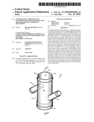
[0053] The details of mixer 20 are seen in FIGS. 1 and 2.
The mixer 20 has a tubular or cylindrically-shaped body 21
defined by a wall 22 which surrounds bore 23. Tubular body
21 has a first inlet 26 in a first inlet end portion 24, and a first
outlet 27 in an outlet end portion 25. The bore 23 communi-
cates with flow inlet 26 and flow outlet 27. Arrows 28, 29
illustrate the direction offlow ofwater in body 21 as shown in
FIG. 2. Curved arrows 30 in FIG. 2 illustrate turbulent flow
that occurs for ensuring that heated water and ambient tem-
perature water thoroughly mix.
[0054] A pair ofconduits are connected to tubular body 21.
These include conduit 31 and conduit 32. Conduit 31 is a
second outlet and removes ambient temperature water from
the bore 23 of tubular body 21. Conduit 32 is a second inlet
and injects heated water into bore 23 of tubular body 21 and
downstream of conduit 31. In this fashion, conduit 31 does
not discharge any heated water from bore 23 oftubular body
21. Rather, the water leaving bore 23 of tubular body 21 via
4
Nov. 25, 2010
conduit 31 is ambient temperature water. This discharge of
ambient temperature from tubular body 21 of mixer 20 is
illustrated by arrows 39 in FIG. 2.
[0055] Each ofthe conduits 31, 32 has a bore. The conduit
31 has bore 33. The conduit 32 has bore 34. Each of the
conduits 31, 32 has an inner end portion and an outer end
portion. Conduit 31 has inner end portion 35 and outer end
portion 36. Conduit 32 has inner end portion 37 and outer end
portion 38. Each of the inner end portions 35, 37 occupies a
position within bore 23 of tubular body 21 as shown in FIG.
2. In this fashion, bore 33 ofconduit 31 occupies a part ofbore
23 oftubular body 21. Similarly, fluid discharging from bore
34 of conduit 32 is discharged directly into the bore 23 of
tubular body 21. The arrows 40 in FIG. 2 illustrate the dis-
charge ofheated water via conduit 32 into bore 23 oftubular
body 21.
[0056] While the angle ofthe longitudinal axis ofbore 33 of
conduit 31 and the angle ofthe longitudinal axis ofbore 34 of
conduit 32 in relation to the longitudinal axis of bore 23 of
tubular body 21 are shown to be about 45 degrees, those
angles could vary from 0 to 90 degrees, and they need not be
the same.
[0057] As can be seen in FIG. 2, first inlet 26 is upstream of
second outlet 31, which is upstream ofsecond inlet 32, which
itself is upstream offirst outlet 27.
[0058] In FIG. 6, flow lines 41 and 42 are used to transfer
water inbetweenmobile heater 12 and mixer 20. The flow line
41 receives water from conduit 31, a second outlet, which is
ambient temperature water and transports that ambient tem-
perature water to vessel 15 ofheater 12. After water has been
heated in vessel 15, it is transported via flow line 42 to conduit
32, a second inlet, of mixer 20. It should be understood that
the flow offluids from flow line 41 to and through vessel 15 of
heater 12 and then to flow line 42 can be a continuous process.
As an example, the flow ofambient temperature water in flow
line 19 can be about 20-150 bbls (2.4-17.9 kl) per minute, and
typically around 60-100 barrels (7.2-11.9 kl) per minute. The
flow rate in flow lines 41 and 42 can be for example a con-
tinuous 7 barrels (0.83 kl) per minute.
[0059] The temperature in the super heated flow line 42 can
be in excess of 200° F. (93.3° C.) and in excess of 240° F.
(116° C.) if flow line 42 is pressurized. Flow lines 43 and 44
illustrate the transfer of warmed water from mixing tanks or
downhole tanks 46 to pumping apparatus 17 and then into the
well 16 for use in frac operations. In FIG. 6, surge tanks 45
can optionally be used downstream ofmixer 20 and upstream
ofmixing tanks 46.
[0060] To achieve higher water temperatures, multiple
heating units 12 can be used to heat the water all of which is
done on a continuous flow basis as shown in FIG. 4. The
moving stream of uniformly heated water can be piped to
surge tank(s) which can be used as a safety bufferbetween the
water flow and the pumping operations, in the case of a
mechanical breakdown or operational problems.
[0061] In FIG. 4, a joint of pipe 47 (commercially avail-
able) can be placed in between the two mixers 20 as shown. In
FIG. 4, the flow of the mixed heated water can be passed
through a second mixer or second mixing manifold 20 and a
portion of the mixed heated water is diverted to a second
heating unit 12 to heat that water to for example between
about 200° F. to 240° F. (93.3° C. to 116° C.). That super-
heated water can be returned to the mixing manifold 20 for
mixing with the continuously moving water stream providing
an additional +10° F. to +15° F. (+5.6° C. to +8.4° C.) uniform
17. US 2010/0294494 Al
elevation ofthe temperature ofthe water flow. This mixed and
heated water can then be piped to mixing tanks 46 for mixing
with any selected hydraulic fracturing chemicals and then
pumpeddown hole for use in the hydraulic fracturing process.
If needed, multiple sequential heating units 12 (and mixers
20) can be attached along the pumping line to continuously
raise the temperature of the continuous flow of water to a
required or target temperature. The mixers 20 can be con-
nected in series (as in FIG. 4) or in parallel or a combination
of series and parallel (as in FIGS. 10 and 12).
[0062] In FIG. 7 (an alternate configuration), the surge
tanks have been eliminated. The mixing tanks 46 can be used
to mix any selected chemical and proppant or proppants with
the water that has been discharged from mixer 20 and that is
ready for use in hydraulic fracturing operation in the well 16.
[0063] Conventional heater trucks 112 shown in FIG. 5
typically produce much less than 20 million BTU (21.1 bil-
lion Joules). They could be used in the system and method of
the present invention, but more robust heating units 12 (such
as those produced by Chandler Manufacturing, Inc. in
Wichita Falls, Tex.) capable of delivery of 22 million BTU
(23.2 billion Joules) or more are preferred. Especially pre-
ferred are diesel powered heater units commercially available
from Chandler Manufacturing, Inc. in which water flows
through a series ofmetal coils, and there are six burners which
heat the coils. An example ofsuch a heater unit can be seen at
www.chandlermfg.comlitem.php?pid=34 and is identified as
an oil-fired frac water heater (and shown in US Patent Publi-
cation no. US 2010/0000508). However, other heater units
which can quickly heat large quantities ofwater can be used.
The diesel powered units are preferred because in colder
environments propane tends to liquifY and not heat as effec-
tively. Preferably one can run 70-100 barrels (8.3-11.9 kl) per
minute per heating truck of the present invention while get-
ting a temperature rise ofat least about 15 degrees Fahrenheit
(8.4° c.).
[0064] Through testing in cold temperatures, the inventor
has learned that heating water from around freezing to about
40 degrees F. (4.4° C.) takes a great degree ofheat. One might
need more heaters 12 when heating water from near freezing,
or one might initially preheat some water in additional frac
tanks (e.g., 3 or 4 up to 50 or 100 frac tanks) to add heat one
needs to move the temperature of the water up from near
freezing to about 40 degrees F. (4.4° C.). One could also add
heating in a water pit itself (e.g., when the water source 11 is
a pond) to help raise the water temperature to around 40 or 45
degrees F. (4.4 or 7.2° C.) (there will be radiant heat loss from
the waterpit, so typically one wouldnot want to heat the water
in the pit much above 40 to 45 degrees F. (4.4 to 7.2° C.))
before further heating the water with the heating system of
present invention shown in FIGS. 3 and 4, for example. The
heating in the water pit could be done with, for example, a
heater or heaters 12 as shown in FIGS. 3 and 4 that circulate
water through hoses 41 and 42 to and from the water pit.
[0065] Also, while typically water freezes at 32 degrees F.
(0° C.), flowing water or water with various substances can
sometimes cool below 32 degrees F. (0° C.) without freezing.
Thus, sometimes the present invention might start processing
water which is below 32 degrees F. (0° C.). Also, sometimes
the source water might have ice in it, but it can still be used if
the water with ice can flow through mixer 20. However, it is
preferred to avoid pulling ice into the intake, as considerable
heat can be lost when melting the ice.
5
Nov. 25, 2010
[0066] Surge or pivot tanks 45 are preferably upright cir-
cular tanks where the water flows in and out (similar to or the
same as the mixing tanks 46 shown in FIG. 6). The agitation
which occurs in the surge tanks 45 is helpful, and seem to add
heat to the water (better mixing seems to occur as well, so
even if surge or pivot tanks 45 are not needed for surge, one
might want to use 2-20 of these anyway).
[0067] Manifolding among multiple surge or pivot tanks
can be done to balance heat. Pivot or surge tanks 45 could be
shaped like mixing tanks 46. Preferably the heated water
flows through the surge tanks (as shown in FIG. 10, where
mixing tanks 46 are acting as surge tanks). The surge tanks
provide a buffer in the event of some breakdown or other
problem making it difficult to produce heater water. During
the breakdown or other problem, heated water from the surge
tanks can be routed to the mixing tanks, even though no
heated water will be refilling the surge tanks. Preferably,
either enough surge tanks are provided that no interruption in
fracing occurs during a breakdown or other problem causing
an interruption in heated water production, or enough surge
tanks are provided that an orderly shutdown offracing occurs
during a breakdown or other problem causing an interruption
in heated waterproduction. Typically surge tanks hold around
480-500 barrels (57.2-59.6 kl) of heated water per tank.
[0068] Though pumps and valves are not shown in the
drawings, appropriate pumps and valves are provided to
direct water as desired, and one ofordinary skill in the art will
be able to determine where to place such pumps and valves to
achieve desired water flow. Water lines can be manifolded
together and several lines could feed and emanate from a
single heating truck.
[0069] Flow rates can be 100 barrels (11.9 kl) per minute
(though this could be higher or lower) and with the preferred
heater trucks ofthe present invention, there will preferably be
around a 15 degree F. (8.4° C.) increase in temperature at 100
barrels (11.9 kl) per minute (for one truck).
[0070] The current normal target water temperature is
70-90 degrees F. (21.1-32.2° C.) (but it could be higher).
Overheating ofthe water is not needed (as one must do when
heating tanks) as the heat loss (if any) using the on-line
heating method ofthe present invention is typically minimal.
[0071] Maintenance oftrucks used in the present invention
includes chemical (e.g., hydrochloric acid) washing of the
coils to keep heat transfer times low (otherwise there can be
buildup on the coils which impedes heat transfer).
[0072] Probably a vertical, round tank (such as mixing tank
46) will work better for mixing hot and cold water to get a
more uniform temperature of water to use in fracing.
[0073] FIG. 8 is similar to FIG. 7, but apparatus 310 shown
therein includes a mixing tank 46 instead ofthe manifold 20
shown in FIG. 7 (anything that could cause turbulence could
be used instead of the manifold 20 shown in FIG. 1, though
the manifold 20 is preferred as it is a relatively simple and
compact mixing device). Water drawn from water source 11
travels through flow line 19 and first inlet 56 into mixing tank
46, where some of the water is drawn off through second
outlet 61 and line 41 into mobile heater 12, then back through
flow line 42 and second inlet 62 into mixing tank 46, where it
then continues to flow through first outlet 57 and flow line 19
to mixing tanks 46 which are near frac pumping apparatus 17.
From there the water flows as in FIG. 7. It is believed that
better mixing ofwater occurs in tank 46 when first inlet 56 is
nearthe bottom oftank 46, first outlet 57 is nearthe top oftank
46, and second inlet 62 is somewhere in between. Also, it is
18. US 2010/0294494 Al
believed that better mixing will occur if mixing tank 46 is a
vertical cylindrical tank as shown in the drawings.
[0074] FIG. 9 is similar to FIG. 8, but apparatus 410 shown
therein includes a half manifold 120 and a mixing tank 46
instead of the manifold 20 shown in FIG. 1. As indicated in
FIG. 9, water at the temperature ofthe water source 11 flows
through half manifold 120, where some of the water is
diverted out through second outlet (conduit) 31 ofhalfmani-
fold 120 into flow line 41 and to heater 12, then out through
flow line 42 into secondinlet 62 ofmixing tank 46. The heated
water from line 42 mixes in mixing tank 46 with the water
which is at the temperature of water source 11 which enters
tank 46 at first inlet 56. The water then flows out through first
outlet 57 through flow line 19 to mixing tanks 46 which are
near frac pumping apparatus 17. From there the water flows as
in FIG. 7.
[0075] FIG. 10 shows apparatus 510, which includes three
mobile heaters 12 with three manifolds 20, two mobile heat-
ers 12 in parallel with one another and located near the water
source 11, and one mobile heater 12 closer to the frac pump-
ing apparatus 17. There are three surge tanks 46 in series with
one of the mobile heaters 12, though these surge tanks 46
could be in series with both mobile heaters 12 which are in
parallel to one another, orthey could be in series with all three
mobile heaters 12 shown in FIG. 10. Further, there could be as
few as none or one surge tank 46 to as many as considered
prudent by the operator, which could be for example three or
four up to 50 or 100 mixing tanks 46 (or even more). Flow of
water through manifolds 20, heaters 12, and surge tanks 46 is
as in prior figures.
[0076] FIG. 11 shows apparatus 610, which includes two
mobile heaters 12 connected directly to the source water 11 (a
pond) with the water being withdrawn from and returned to
the pond. There are also three mobile heaters 12, each con-
nected to a mixing tank 46, heating water in the mixing tanks
46. Further, there could be as few as none or one surge tank 46
and associated mobile heaters 12 to as many as considered
prudent by the operator, which could be for example three or
four up to 50 or 100 mixing tanks 46 with associated mobile
heaters 12 (or even more).
[0077] FIG. 12 is similar to FIG. 11, but in FIG. 12 appa-
ratus 710 differs from apparatus 610 in that one truck has
moved from the pond 11 and is heating the water as it runs
through the flow line 19. FIG. 12 shows three additional
mixing tanks 46 in series with pipe 19 and acting as surge
tanks. As in FIG. 11, there are also three mobile heaters 12,
each connected to a mixing tank 46, heating water in the
mixing tanks 46.
[0078] These mixing tanks 46 are in series with one another
in a flow line 119 which rnns parallel to flow line 19 and then
feeds into flow line 19. Further, there could be as few as none
or one surge tank 46 and associated mobile heaters 12 to as
many as considered prudent by the operator, which could be
for example three orfour up to 50 or 100 mixing tanks 46 with
associated mobile heaters 12 (or even more).
[0079] There is a huge lake (Lake Sakakawea) in the middle
of westem North Dakota. Fracing operations were making a
tremendous strain on groundwater. Now it is expected that
water will be pulled from Lake Sakakawea with permits cur-
rently in process. It is believedthat companies will soonpump
water out of Lake Sakakawea and put it into insulated tanks,
where it will be heated in the tanks. The water will then be
taken via insulated trucks to a well site where fracing opera-
tions occur. The apparatus of the present invention can heat
6
Nov. 25, 2010
water as it is pumped from the lake into the tanks (and it can
continue to heat the water once it is in the tanks). This method
can occur in other areas as well.
[0080] The following is a list ofparts and materials suitable
for use in the present invention:
Parts Number
10
11
12
13
14
15
16
17
18
19
20
21
22
23
24
25
26
27
28
29
30
31
32
33
34
35
36
37
38
39
40
41
42
43
44
45
46
47
56
57
61
62
110
112
119
120
210
310
410
510
610
710
PARTS LIST
Description
hydraulic fracturing pumping system
water source
mobile heater apparatus
truck
trailer
vessel
oil and/or gas well
frac pumping apparatus
trailer
flow line
mixer
tubular/cylindrically-shaped body
wall
bore
inlet end portion
outlet end portion
inlet
outlet
arrow
arrow
curved arrow
conduit (second outlet)
conduit (second inlet)
bore
bore
inner end portion
outer end portion
inner end portion
outer end portion
arrow
arrow
flow line
flow line
flow line
flow line
surge tank
mixing tank or downhole tank or surge tank
joint ofpipe
inlet (first) ofmixing tank 46
outlet (first) ofmixing tank 46
second outlet ofmixing tank 46
second inlet ofmixing tank 46
hydraulic fracturing pumping system
prior art mobile heating truck
flow line
halfmanifold
hydraulic fracturing pumping system
hydraulic fracturing pumping system
hydraulic fracturing pumping system
hydraulic fracturing pumping system
hydraulic fracturing pumping system
hydraulic fracturing pumping system
[0081] All measurements disclosed herein are at standard
temperature and pressure, at sea level on Earth, nnless indi-
cated otherwise.
[0082] The foregoing embodiments are presented by way
of example only; the scope of the present invention is to be
limited only by the following claims.
19. US 2010/0294494 Al
1. A method of fracturing an oil and/or gas producing
formation, comprising the steps of:
a) providing a transportable heating apparatus for heating
water to a temperature ofat least about 40 degrees F. (4.4
degrees C.);
b) transmitting a water stream of cool or cold water to a
mixer, the cool or cold water stream being at a tempera-
ture of less than a predetermined target temperature;
c) the mixer having a first inlet that receives cool or cold
water from the stream of step b and a first outlet that
enables discharge of a substantially continuous stream
which is a mix of cool or cold and hot water;
d) the mixerhaving a second inlet that enables heated water
to enter the mixer;
e) adding heated water from the transportable heating
apparatus of step a to the mixer via the second inlet;
f) wherein the volume ofwater of step b is much greater
than the volume of water of step e;
g) adding a selected proppant to the water discharged from
the mixer after step f'; and
h) transmitting the water andthe proppant into an oil and/or
gas producing formation, wherein water flows substan-
tially continuously from the first inlet to the first outlet
during the fracturing process.
2. The method of claim 1 wherein the mixer has a tubular
body with a bore.
3. The method ofclaim 2 wherein the tubular body bore has
a central longitudinal axis and in step e the heated water
enters the mixer bore at an angle.
4. The method ofclaim 2 wherein the tubular body bore has
a central longitudinal axis and in step f' the water discharges
from the mixer bore at an angle.
5. The method ofclaim 1 wherein the heated water and the
cool or cold water
6. The method ofclaim 1 wherein the transportable heating
apparatus is a wheeled vehicle.
7. The method of claim 1 wherein the cool or cold water
stream has a temperature ofbetween about 33 and 80 degrees
F. (0.6 and 27 degrees C.).
8. The method ofclaim 1 whereinthe cool water stream has
a temperature of above freezing.
9. The method of claim 1 wherein in step e the heated
water stream has a temperature ofbetween about 40 and 120
degrees F. (4.4 and 48.9 degrees C.).
10. The method of claim 1 wherein in step e the heated
water stream has a temperature ofbetween about 40 and 150
degrees F. (4.4 and 65.6 degrees C.).
11. The method of claim 1 wherein in step e the heated
water stream has a temperature ofbetween about 40 and 200
degrees F. (4.4 and 93.3 degrees C.).
12. The method of claim 1 wherein there are two mixers
connected together in series in steps b through e.
13. The method of claim 1 further comprising adding
chemicals to the water during step g.
14. A method of fracturing an oil and/or gas producing
formation, comprising the steps of:
a) providing a transportable heating apparatus that heats
water to a temperature of at least 40 degrees F. (4.4
degrees C.);
b) transmitting a water stream of cool or cold water to a
mixer, the cool water stream being at a temperature of
less than a predetermined target temperature;
7
Nov. 25, 2010
c) the mixer having a first inlet that receives cool or cold
water from the source of step b and a first outlet that
enables discharge of a substantially continuous stream
which is a mix of water;
d) the mixer having a second outlet and a second inlet
downstream of the second outlet;
e) adding heated water from the transportable heating
apparatus of step a to the mixer via the second inlet;
f) continuously transmitting water from the mixer via the
second inlet to the heating apparatus of step a;
g) wherein the volume ofwater ofstep b is much greater
than the volume of water of step e;
h) adding a selected proppant to the water discharged from
the mixer after step f'; and
i) transmitting the water and the proppant into an oil and/or
gas producing formation, wherein water flows substan-
tially continuously from the first inlet to the first outlet
during the fracturing process.
15. The method ofclaim 14 wherein the mixer has a tubular
body with a bore.
16. The method ofclaim 15 wherein the tubular body bore
has a central longitudinal axis and in step ethe heated water
enters the mixer bore at an angle.
17. The method ofclaim 15 wherein the tubular body bore
has a central longitudinal axis and in step f' the water dis-
charges from the mixer bore at an angle.
18. The method of claim 14 wherein the heated water and
the cool or cold water mix in step e with turbulent flow.
19. The method of claim 14 wherein the transportable
heating apparatus is a wheeled vehicle.
20. The method ofclaim 14 wherein the cool or cold water
stream has a temperature ofbetween about 33 and 80 degrees
F. (0.6 and 27 degrees C.).
21. The method ofclaim 14 wherein in step e the heated
water stream has a temperature ofbetween about 40 and 200
degrees F. (4.4 and 93.3 degrees C.).
22. The method ofclaim 14 wherein in step e the heated
water stream has a temperature ofbetween about 40 and 150
degrees F. (4.4 and 65.6 degrees C.).
23. The method ofclaim 14 wherein in step e the heated
water stream has a temperature ofbetween about 40 and 120
degrees F. (4.4 and 48.9 degrees C.).
24. The method of claim 14 wherein there are two mixers
connected together in series in step b through e.
25. The method of claim 14 wherein there are two mixers
connected together in parallel in step b through e
26. The method of claim 14 further comprising adding
chemicals to the water during step h.
27. An oil well hydraulic fracturing system, comprising:
a) a transportable heating apparatus that heats water to a
temperature ofat least 40 degrees F. (4.4 degrees C.);
b) a source ofwater at about ambient temperature;
c) a mixer having a first inlet and a first outlet;
d) a second inlet that enables heated water to enter the
mixer;
e) a second outlet that enables removal of water from the
mixer upstream of the second inlet;
f) a first flowline that transmits water between the heater
and the second inlet;
g) a second flowline that transmits water between the sec-
ond outlet and the heater, the second flowline being
upstream of the second inlet; and
20. US 2010/0294494 Al
h) a mixing tank that is receptive of water flow from the
mixer, said tank enabling a proppant to be mixed with
water that is discharged from the first outlet.
28. The oil well hydraulic fracturing system of claim 27
wherein the mixer has a tubular body.
29. The oil well hydraulic fracturing system of claim 28
wherein the tubular body has a central longitudinal axis and
heated water enters the mixer at an angle via the second inlet.
30. The oil well hydraulic fracturing system of claim 28
wherein the tubular body has a central longitudinal axis and
water discharges from the mixer at an angle via the second
outlet.
31. The oil well hydraulic fracturing system of claim 27
wherein the mixer is configured to mix heated water and
ambient temperature water with turbulent flow downstream
of second outlet.
32. The oil well hydraulic fracturing system of claim 27
wherein the heating apparatus is a wheeled vehicle.
33. The oil well hydraulic fracturing system of claim 27
wherein the source of water has a temperature of between
about 33 and 80 degrees F. (0.6 and 27 degrees C.).
34. The oil well hydraulic fracturing system of claim 27
wherein the heated water in the first flowline has a tempera-
ture of between about 120 and 240 degrees F. (48.9 and 116
degrees C.).
35. The oil well hydraulic fracturing system of claim 27
wherein the mixer is connected in series with a second mixer
so that the flow of water discharged from the first outlet is
transmitted to the second mixer.
36. The oil well hydraulic fracturing system of claim 27
wherein the mixing tank also enables chemicals to be mixed
with the water.
37. A hydraulic fracturing apparatus, comprising:
a) a heating apparatus for heating water to a temperature of
at least 40 degrees F. (4.4 degrees C.);
b) a source of water;
c) a mixer having a first inlet that receives water from the
source of water and a first outlet that enables discharge
ofa mix of water;
d) the mixer having a second outlet and a second inlet
spaced downstream of the second outlet;
e) a first flowline that transmits water from the heating
apparatus to the mixer via the second inlet;
f) a second flowline that transmits water from the mixer to
the heating apparatus via the second outlet;
g) a tank that enables a selected proppant to be mixed with
the water that is discharged from the mixer;
h) a flowline that connects the mixer with the tank;
i) a flowline that transmits water and proppant from the
tank into an oil and/or gas producing formation.
38. The hydraulic fracturing apparatus ofclaim 37 wherein
the mixer has a tubular body.
39. The hydraulic fracturing apparatus ofclaim 38 wherein
the tubular body has a central longitudinal axis and the heated
water enters the mixer at an angle.
40. The hydraulic fracturing apparatus ofclaim 38 wherein
the tubular body has a central longitudinal axis and water
discharges from the mixer through the second outlet at an
acute angle with respect to said axis.
41. The hydraulic fracturing apparatus ofclaim 37 wherein
the heated water and the water from the source of water mix
with turbulent flow in the mixer.
42. The hydraulic fracturing apparatus ofclaim 37 wherein
the heating apparatus is a wheeled vehicle.
8
Nov. 25, 2010
43. The hydraulic fracturing apparatus ofclaim 37 wherein
the water source has a temperature of between about 33 and
80 degrees F. (0.6 and 27 degrees C.).
44. The hydraulic fracturing apparatus ofclaim 37 wherein
the water in the first flowline has a temperature of between
about 120 and 240 degrees F. (48.9 and 116 degrees C.).
45. The hydraulic fracturing apparatus ofclaim 37 wherein
there are two or more mixers connected together in series.
46. The hydraulic fracturing apparatus ofclaim 37 wherein
there are two or more mixers connected together in parallel.
47. The hydraulic fracturing apparatus ofclaim 37 wherein
the volume of water flowing in the first flowline is smaller
than the volume of water flowing in the mixer.
48. The hydraulic fracturing apparatus ofclaim 37 wherein
the volume of water flowing in the first flowline is less than
halfthe volume of water flowing in the mixer.
49. The hydraulic fracturing apparatus ofclaim 37 wherein
the volume ofwater flowing inthe first flowline is less thanten
percent the volume of water flowing in the first inlet.
50. The oil well hydraulic fracturing system of claim 37
wherein the tank also enables chemicals to be mixed with the
water.
51. A method of fracturing an oil and/or gas producing
formation, comprising the steps of:
a) providing a transportable heating apparatus for heating
water to a temperature ofat least about 40 degrees F. (4.4
degrees C.);
b) transmitting a water stream of cool or cold water to a
mixer, the cool or cold water stream being at a tempera-
ture of less than a predetermined target temperature;
c) the mixer having an inlet that receives cool or cold water
from the stream of step b and an outlet that enables
discharge of a substantially continuous stream which is
a mix of cool or cold and hot water;
d) the mixer having a lateral inlet fitting that enables heated
water to enter a mixer bore at an angle;
e) adding heated water from the transportable heating
apparatus of step a to the mixer via the lateral inlet
fitting;
f) wherein the volume ofwater of step b is much greater
than the volume of water of step e;
g) adding a selected proppant to the water discharged from
the mixer after step f'; and
h) transmitting the water andthe proppant into an oil and/or
gas producing formation, wherein water flows substan-
tially continuously from the inlet to the outlet during the
fracturing process.
52. The method ofclaim 51 wherein the mixer has a tubular
body with a bore, one endofthe bore being the mixer inlet and
the other end of the bore being the mixer outlet.
53. The method ofclaim 52 wherein the tubular body bore
has a central longitudinal axis and in step ethe heated water
enters the mixer bore at an acute angle.
54. The method ofclaim 52 wherein the tubular body bore
has a central longitudinal axis and in step f' the water dis-
charges from the mixer bore at an acute angle.
55. The method of claim 51 wherein the heated water and
the cool or cold water mix in step e with turbulent flow.
56. The method of claim 51 wherein the transportable
heating apparatus is a wheeled vehicle.
57. The method ofclaim 51 wherein the cool or cold water
stream has a temperature ofbetween about 33 and 80 degrees
F. (0.6 and 27 degrees C.).
21. US 2010/0294494 Al
58. The method ofclaim 51 wherein the cool water stream
has a temperature of above freezing.
59. The method ofclaim 51 wherein in step e the heated
water stream has a temperature ofbetween about 40 and 120
degrees F. (4.4 and 48.9 degrees C.).
60. The method ofclaim 51 wherein in step e the heated
water stream has a temperature ofbetween about 40 and 150
degrees F. (4.4 and 65.6 degrees C.).
61. The method ofclaim 51 wherein in step e the heated
water stream has a temperature ofbetween about 40 and 200
degrees F. (4.4 and 93.3 degrees C.).
62. The method of claim 51 wherein there are two mixers
connected together in series in step b through e.
63. The method of claim 51 further comprising adding
chemicals to the water during step g.
64. A method of fracturing an oil producing formation,
comprising the steps of:
a) providing a transportable heating apparatus that heats
water to a temperature of at least 40 degrees F. (4.4
degrees C.);
b) transmitting a water stream of cool or cold water to a
mixer, the cool water stream being at a temperature of
less than a predetermined target temperature;
c) the mixer having an inlet that receives cool or cold water
from the source of step b and an outlet that enables
discharge of a substantially continuous stream which is
a mix of water;
d) the mixer having a first lateral inlet fitting and a second
lateral inlet fitting downstream of the first inlet fitting;
e) adding heated water from the transportable heating
apparatus of step a to the mixer via the second lateral
inlet fitting;
f) continuously transmitting water from the mixer via the
first lateral inlet fitting to the heating apparatus of step
a;
g) wherein the volume ofwater ofstep b is much greater
than the volume of water of step e;
h) adding a selected proppant to the water discharged from
the mixer after step f'; and
i) transmitting the water and the proppant into an oil and/or
producing formation, wherein water flows substantially
continuously from the first inlet to the first outlet during
the fracturing process.
65. The method ofclaim 64 whereinthe mixerhas a tubular
body with a bore, one endofthe bore being the mixer inlet and
the other end ofthe bore being the mixer outlet.
66. The method ofclaim 65 wherein the tubular body bore
has a central longitudinal axis and in step e the heated water
enters the mixer bore at an acute angle.
67. The method ofclaim 65 wherein the tubular body bore
has a central longitudinal axis and in step f' the water dis-
charges from the mixer bore at an acute angle.
68. The method of claim 64 wherein the heated water and
the cool or cold water mix in step e with turbulent flow.
69. The method of claim 64 wherein the transportable
heating apparatus is a wheeled vehicle.
70. The method ofclaim 64 wherein the cool or cold water
stream has a temperature ofbetween about 33 and 80 degrees
F. (0.6 and 27 degrees C.).
71. The method ofclaim 64 wherein in step e the heated
water stream has a temperature ofbetween about 40 and 200
degrees F. (4.4 and 93.3 degrees C.).
9
Nov. 25, 2010
72. The method ofclaim 64 wherein in step e the heated
water stream has a temperature ofbetween about 40 and 150
degrees F. (4.4 and 65.6 degrees C.).
73. The method ofclaim 64 wherein in step e the heated
water stream has a temperature ofbetween about 40 and 120
degrees F. (4.4 and 48.9 degrees C.).
74. The method of claim 64 wherein there are two mixers
connected together in series in step b through e.
75. The method of claim 64 wherein there are two mixers
connected together in parallel in step b through e.
76. The method of claim 64 further comprising adding
chemicals to the water during step h.
77. An oil well hydraulic fracturing system, comprising:
a) a transportable heating apparatus that heats water to a
temperature ofat least 40 degrees F. (4.4 degrees C.);
b) a source ofwater at about ambient temperature;
c) a mixer having an inlet, an outlet and a mixer bore that
extends between the inlet and the outlet;
d) a first lateral fitting on the mixer that enables heated
water to enter the mixer bore;
e) a second lateral fitting on the mixer that enables removal
ofwater from the mixer bore upstream ofthe first lateral
fitting and wherein at least one ofthe lateral fittings has
a wall portion that extends into the mixer bore;
f) a first flowline that transmits water between the heater
and the first lateral fitting;
g) a second flowline that transmits water between the sec-
ond lateral fitting and the heater, the second flowline
being upstream ofthe first lateral fitting; and
h) a mixing tank that is receptive of water flow from the
bore of the mixer, said tank enabling a proppant to be
mixed with water that is discharged from the mixer
outlet.
78. The oil well hydraulic fracturing system of claim 77
wherein the mixer has a tubular body with a bore, one end of
the bore being the mixer inlet and the other end of the bore
being the mixer outlet.
79. The oil well hydraulic fracturing system of claim 78
wherein the tubular body bore has a central longitudinal axis
and heated water enters the mixer bore at an acute angle via
the first lateral fitting.
80. The oil well hydraulic fracturing system of claim 78
wherein the tubular body bore has a central longitudinal axis
and water discharges from the mixerbore at an acute angle via
the second lateral fitting.
81. The oil well hydraulic fracturing system of claim 77
wherein the mixer is configured to mix heated water and
ambient temperature water with turbulent flow downstream
ofone ofthe lateral fittings.
82. The oil well hydraulic fracturing system of claim 77
wherein the heating apparatus is a wheeled vehicle.
83. The oil well hydraulic fracturing system of claim 77
wherein the source of water has a temperature of between
about 33 and 80 degrees F. (0.6 and 27 degrees C.).
84. The oil well hydraulic fracturing system of claim 77
wherein the heated water in the first flowline has a tempera-
ture of between about 120 and 240 degrees F. (48.9 and 116
degrees C.).
85. The oil well hydraulic fracturing system of claim 77
wherein the mixer is connected in series with a second mixer
so that the flow ofwater discharged from the first mixer outlet
is transmitted to the second mixer.
22. US 2010/0294494 Al
86. The oil well hydraulic fracturing system of claim 77
wherein the mixing tank also enables chemicals to be mixed
with the water.
87. A hydraulic fracturing apparatus, comprising:
a) a heating apparatus for heating water to a temperature of
at least 40 degrees F. (4.4 degrees C.);
b) a source of water;
c) a mixer having an inlet that receives water from the
source ofwater and an outlet that enables discharge ofa
mix of water;
d) the mixer having a first lateral inlet fitting and a second
lateral inlet fitting spaced downstream of the first inlet
fitting;
e) a first flowline that transmits water from the heating
apparatus to the mixer via the second lateral inlet fitting;
f) a second flowline that transmits water from the mixer to
the heating apparatus via the first lateral inlet fitting;
f) a tank that enables a selected proppant to be mixed with
the water that is discharged from the mixer;
g) a flowline that connects the mixer bore with the tank;
h) a flowline that transmits water and proppant from the
tank into an oil and/or gas producing formation.
88. The hydraulic fracturing apparatus ofclaim 87 wherein
the mixer has a tubular body with a bore, one end ofthe bore
being the mixer inlet and the other end of the bore being the
mixer outlet.
89. The hydraulic fracturing apparatus ofclaim 88 wherein
the tubular body bore has a central longitudinal axis and the
heated water enters the mixer bore at an acute angle.
90. The hydraulic fracturing apparatus ofclaim 88 wherein
the tubularbody bore has a central longitudinal axis and water
10
Nov. 25, 2010
discharges from the mixer bore via the first lateral inlet fitting
at an acute angle with respect to said axis.
91. The hydraulic fracturing apparatus ofclaim 87 wherein
the heated water and the water from the source of water mix
with turbulent flow in the mixer bore.
92. The hydraulic fracturing apparatus ofclaim 87 wherein
the heating apparatus is a wheeled vehicle.
93. The hydraulic fracturing apparatus ofclaim 87 wherein
the water source has a temperature of between about 33 and
80 degrees F. (0.6 and 27 degrees C.)
94. The hydraulic fracturing apparatus ofclaim 87 wherein
the water in the first flowline has a temperature of between
about 120 and 240 degrees F. (48.9 and 116 degrees C.).
95. The hydraulic fracturing apparatus ofclaim 87 wherein
there are two or more mixers connected together in series.
96. The hydraulic fracturing apparatus ofclaim 87 wherein
there are two or more mixers connected together in parallel.
97. The hydraulic fracturing apparatus ofclaim 87 wherein
the volume of water flowing in the first flowline is smaller
than the volume of water flowing in the mixer bore.
98. The hydraulic fracturing apparatus ofclaim 87 wherein
the volume of water flowing in the first flowline is less than
halfthe volume of water flowing in the mixer bore.
99. The hydraulic fracturing apparatus ofclaim 87 wherein
the volume ofwater flowing inthe first flowline is less thanten
percent the volume of water flowing in the mixer bore.
100. The oil well hydraulic fracturing system of claim 87
wherein the tank also enables chemicals to be mixed with the
water.
101. (canceled)
* * * * *