Rack-mounted climate control for 482.6 mm (19 ̋), air throughput 320/480 m3/h
•
0 likes•639 views

1) Rittal offers rack-mounted climate control components like fans and cooling units that integrate directly into their 19" enclosure systems to provide effective cooling. 2) Options include rack-mounted fans, centrifugal fans, and rack-mounted cooling units with 1000W of cooling capacity. 3) Rittal's climate control components mount directly onto the 19" mounting levels below electronic components to guarantee effective cooling and prevent hot spots.

Recommended
More Related Content
What's hot
What's hot (19)
Similar to Rack-mounted climate control for 482.6 mm (19 ̋), air throughput 320/480 m3/h
Similar to Rack-mounted climate control for 482.6 mm (19 ̋), air throughput 320/480 m3/h (20)
More from erdinc klima
More from erdinc klima (20)
Recently uploaded
Recently uploaded (20)
Rack-mounted climate control for 482.6 mm (19 ̋), air throughput 320/480 m3/h
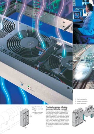
- 1. 144 1 3 2 19˝ enclosure Rack-mounted fan Rack-mounted cooling units 1 2 3 Practical example of rack- mounted climate control Climate control components for 482.6 mm (19˝) enclosures may be integrated into the enclosure systems with the minimal assembly effort, with no need for intensive machining work. A comprehensive range, specifically equipped to meet the require- ments of the IT sector, offers system solu- tions to suit all application areas. Centrifu- gal fans, rack-mounted fans and active rack-mounted cooling units are available for integration into the enclosure systems or subracks. 23 1 Roof-mounted fan Network enclosure Server enclosure 1 2 3
- 2. 145 Climate control tailored to enclosures Climatecontroltailoredtoenclosures Climate control tailored to enclosures Rack-mounted climate control 146 Ventilation systems/outdoor climate control 147 For 482.6 mm (19˝), useful cooling output 1000 W 148 For 482.6 mm (19˝), air throughput 320/480 m3/h 150 Air throughput 320 m3/h 152 The Rittal climate control range is as comprehensive as the requirements are diverse. 482.6 mm (19˝) rack-mounted climate control is specifically designed to accommodate electronic require- ments. Coordinated ventilation concepts are available for specific enclosure systems. For outdoor enclosures too, you can always rely on Rittal to create the right climate. 1 2 3 Practical example of outdoor climate control Protection from the most adverse weather conditions is a clear requirement for elec- tronics that are used outdoors. In such cases, special enclosures with inte- gral climate control offer the ideal solution – system components such as heat exchan- gers, cooling units and heaters create the correct climate. Practical example of ventilation systems: Ventilation concepts tailored to enclosure systems, such as roof-mounted fans, con- sisting of a single unit of fan and enclo- sure roof, eliminate the need for time-con- suming mounting cutouts and are easily and quickly installed. Modular air routing concepts such as internal fan mounting panel or as fan cross member for venti- lated server doors are based on the same platform concept. They ensure good air circulation inside the enclosure and pre- vent the formation of hot spots. Fan systems for TS 8 Top enclosure system 154 Geothermal heat exchanger Terravent 158 CS Outdoor enclosure Door-mounted heat exchanger Heater 1 2 3
- 3. 146 Climate control tailored to enclosures Rack-mounted climate control Rittal system climate control Air throughput 320/480 m3/h, 1 U Direct ventilation of the subracks and per- manent air circulation prevent hot spots and heat accumulation from occurring. The fan units (24 V DC, 115 – 230 V AC) are also available with integral speed control and fault evaluation. Rack-mounted fan The fully wired unit ready for connection is installed directly in the 482.6 mm (19˝) level ➀. Vario rack-mounted fan with guide frame offers service benefits The rack-mounted fan slides into the guide frame like a drawer. Connectors on the rear ensure immediate contact. It is locked by means of a quick-release fastener. Installation options for the guide frame: ● Directly in the subrack ➁ ● Via two mounting brackets on the 482.6 mm (19˝) mounting level ➂ All rack-mounted climate control components are fitted directly onto the 482.6 mm (19˝) mounting level for subracks. Because they are positioned directly below the electronic components, effective cooling and the avoidance of hot spots are guaranteed. Benefits: ● Rapid installation on 482.6 mm (19˝) mounting levels ● Direct, effective dissipation of heat loss, thanks to positioning beneath the assemblies ● No externally mounted equipment to disrupt the aesthetic appearance of the enclosure Useful cooling output 1000 W, 6 U This is the ideal solution when the enclo- sure internal temperature needs to be cooled to below the ambient temperature. The heated air is drawn in, cooled, and blown beneath the rack-mounted elec- tronics to be cooled. Simple mounting on the 482.6 mm (19˝) level Preferably in the bottom section of the enclosure. Solid enclosures require a door cutout for the external air circuit. With open enclosures, a fully equipped front is essen- tial. The setpoint of the temperature control- ler is set via a service flap. 2 1 3 320 m3/h air throughput, 2 U The high air throughput means that Rittal centrifugal fans are capable of dissipating large heat losses from the enclosure. The ambient air is drawn in via the front grille and conveyed upwards. The minimal noise generation of 52 dB creates a pleasant work- ing environment. Rack-mounted cooling units Rack-mounted fan Centrifugal fan
- 4. 147 Ventilation systems / outdoor climate control Rittal system climate control Climatecontroltailoredtoenclosures Ready-to-use, wired modules equipped with fans for numerous Rittal enclosure system platforms offer effective air throughput and minimal assembly work. Fan roofs, fan cross members for server enclosures (door installation), internal fan mounting panels and enclosure internal fans are all available. Benefits: ● Fast assembly ● Targeted air routing to avoid hot spots ● Perfect system integration For all enclosures: Roof-mounted fans, passive or active May be integrated into any enclosure roof area with suit- able dimensions for the mount- ing cutout. For TS 8: Fan roof, modular In exchange for the existing roof plate. Fan and cable entry are pre-integrated. Fan mounting plate Installation in the enclosure in conjunction with spacer bolts or the vented roof plate for cable entry. For flexRack: Active fan insert For retrospective mounting in the cutout of the roof plate with vent panel. Further information can be found in the latest IT Catalogue. For QuickRack: Modular fan mounting plate Pre-assembled for simple and versatile roof configuration. Further information can be found in the latest IT Catalogue. For TS 8: Fan cross-members for server enclosures Specifically for installation in the tubular door frame of perfo- rated doors. For TS 8: Internal fan mounting panel Twin-walled side panel for tar- geted air routing. Enclosure internal fan Supports active climate control components and thereby avoids hot spots. For TS 8: Air baffle system Cold air from the hollow base is routed to the twin-walled door via an air routing nozzle and distributed in a targeted manner. Further information can be found in the latest IT Catalogue. The requirements of outdoor enclosures for cooling and the avoidance of condensation are met to perfection: Special heat exchangers, geothermal heat exchangers, cooling units and heaters are all available. Further information may be found in the latest CS brochure. Fans for integration into the roof Fan for integration into the door Air baffle systems Outdoor climate control
- 5. 148 Rittal system climate control 54238 445 3 482.6 (19″) 190.5 6HE=265.9 6.8 x 10.3 220 8032 Technical specifications: ● The device slides easily into pre-config- ured 482.6 mm (19˝) electronic enclo- sures. ● A service flap facilitates adjustment and control of the thermostat. ● The refrigeration system is entirely maintenance-free. ● The combined high/low pressure monitor (to VBG 20, § 7), thermally controlled expansion valve and ball bearing- mounted fans with thermal winding pro- tection give the unit a high standard of safety. ● The low pressure monitor prevents the refrigeration system from icing. Supply includes: Wired ready for connection with connection cable (3 m), including drilling template. Model No. SK 3278.134* 3292.134 Rated operating voltage V, Hz 115, 50/60 230, 50/60 Dimensions in mm W H D 445 265.9 (6 U) 542 Useful cooling output Q . K to DIN 3168 L 35 L 35 L 35 L 50 1000 W/1050 W 660 W/770 W Rated current max. 8.4 A/10.8 A 3.8 A/4.5 A Start-up current 21.0 A/22.0 A 10.0 A/11.8 A Pre-fuse T 10.0 A/16.0 A 6.0 A/6.0 A Power consumption Pel to DIN 3168 L 35 L 35 L 35 L 50 615 W/710 W 680 W/800 W 585 W/650 W 650 W/720 W Refrigeration factor ε = Q . K/Pel L 35 L 35 1.6 1.7 Refrigerant R134a, 700 g Permissible operating pressure p. max. 25 bar Temperature and setting range +20°C to +55°C Protection category to EN 60 529/10.91 External circuit IP 34 Internal circuit IP 54 Duty cycle 100% Type of connection Connection cable 3 m Weight 38 kg 35 kg Colour RAL 7032 Air throughput of fans External circuit 620 m3/h Internal circuit 460 m3/h Temperature control Internal thermostat (factory setting +35°C) Special voltages available on request. We reserve the right to make technical modifications. Accessories Packs of Page Filter mats 3 3286.000 182 Adaptor for front air supply 1 3259.000 173 Air duct 10 3220.000 173 Temperature indicator 1 3114.115 3114.100 174 Door-operated switch 1 4127.000 176 * Delivery times available on request. SK 3278.134 / SK 3292.134 View of the rear of the unit Air duct, extendible to any length = Service flap (thermostat)1 1 HE = U
- 6. Rack-mounted cooling units for 482.6 mm (19˝), useful cooling output 1000 W 149Rittal system climate control Rack-mountedcoolingunits Tu = Ambient temperature (°C) QK = Continuous useful cooling output (W) Ti = Enclosure internal temperature (°C) . Suitable for mounting in enclo- sures with front doors (sheet steel or acrylic) by means of an adaptor for front air supply. Approvals, see page 23. Performance diagrams Model No. SK 3278.134 / 3292.134 60 Hz QK . Ti Tu 1300 300 500 1700 1500 50 45 40 35 25 30 20 20 25 30 35 4540 700 1100 900 5550 55 50 Hz 300 400 500 600 700 800 900 1000 1100 1200 1300 20 25 30 35 40 45 50 55 1400 1500 1600 1800 Ti 20 25 30 35 4540 50 55 QK . Tu Functional diagram US patent no. 4,882,911 European patent no. 0 312 853 with validity for DE, FR, IT Japanese patent no. 239 867/88 Also required: For installation in a closed enclosure: Adaptor for front air supply and air duct for waste air, see accessories. ENVIRONMENTALLY FRIENDLY C OO L I N G T E C H N O LO GY
- 7. 150 Rittal system climate control 410 73 100 482.6 (19″) 180 200 43.6 (1HE) 85/105 2 206 214 432 120 55 482.6 (19″) 426 43.6 (1HE) 85/105 1 2 Technical specifications: Rack-mounted fan ● Versions with a distance between axes − of 85 mm for 160 mm deep PCBs, − of 105 mm for 220 mm deep PCBs. ● SK 3342.500: Fan unit with speed moni- toring. Fault evaluation via floating con- tact. Technical specifications: Vario rack-mounted fan ● With an additional guide frame, may be used in: − Subrack 84 HP − 482.6 mm (19˝) mounting angles. ● The guide frame offers a high level of flexibility, i.e. simply slide in the fan insert, lock into position and voilà! ● Tapped strips inserted in the guide frame ensure variable positioning of the fan insert in the subrack. ● Fitted rack connectors ensure secure, problem-free connection. ● SK 3352.500: Fan unit with speed moni- toring. Fault evaluation via floating con- tact. Rack-mounted fan/Vario rack-mounted fan supply includes: Wired unit ready for connection, including terminal strip and assembly parts. Guide frame supply includes: Guide frame including connector and fit- ted connection cable (3 m), bracket for optional attachment to the 482.6 mm (19˝) system, assembly parts. SK rack-mounted fan Vario SK rack-mounted fan Model No. SK Model No. SK 2 fans, distance between axes 85 mm 3340.0241) 3340.1151) 3340.230 – 3350.0241) 3350.1151) 3350.230 – 3 fans, distance between axes 85 mm 3341.0241) 3341.115 3341.230 – 3351.0241) 3351.1151) 3351.230 – 3 fans, distance between axes 105 mm 3342.024 3342.1151) 3342.230 3342.5002) 3352.0241) 3352.1151) 3352.230 3352.5001)2) Rated operating voltage V 24 V (DC) 115 V (AC) 230 V (AC) 24 V (DC) 115 – 230 V (AC) 24 V (DC) 115 V (AC) 230 V (AC) 24 V (DC) 115 – 230 V (AC) Model No. guide frame to fit SK – – – – 3356.1001) 3355.100 3355.100 3357.1001) 1) Extended delivery times 2) Version with monitoring Accessories Page Temperature indicator 230 V (AC) 174 3114.100 3114.115 3114.100 3114.024 3114.100 3114.115 3114.100 3114.024 Thermostat 175 3110.000 3110.000 Speed control 176 3120.000 3120.115 3120.000 – 3120.000 3120.115 3120.000 – Rack-mounted fan May be fitted between a pair of 482.6 mm (19˝) mounting angles. Vario rack-mounted fan With an additional guide frame, may be used in: ● Subrack 84 HP ● 482.6 mm (19˝) mounting angles. Mounted between a pair of 482.6 mm (19˝) mounting angles Mounting in subracks 84 HP Mounted between a pair of 482.6 mm (19˝) mounting angles Technical specifications Model No. SK 3340.230 3350.230 3340.115 3350.115 3340.024 3350.024 3341.230 3351.230 3342.230 3352.230 3341.115 3351.115 3342.115 3352.115 3341.024 3351.024 3342.024 3352.024 3342.5002) 3352.500 2) Rated operating voltage V, Hz AC 230 V 50/60 Hz AC 115 V 50/60 Hz DC 24 V – AC 230 V 50/60 Hz AC 115 V 50/60 Hz DC 24 V – DC 24 V AC 115 – 230 V 50/60 Hz Rated current max. 0.24 A/0.22 A 0.46 A/0.46 A 0.49 A 0.36 A/0.33 A 0.69 A/0.69 A 0.74 A 0.85 A Pre-fuse T 6 A Number of fans 2 3 Air throughput, unimpeded air flow 320 m3/h 480 m3/h Temperature range –10°C to +55°C Noise level 51 dB (A) 52 dB (A) 51 dB (A) 51 dB (A) 52 dB (A) 51 dB (A) LED display (version with monitoring) Distance between axes Mounting bracket for installation Distance between axes Guide frame LED display (version with monitoring) HE = U
- 8. Rack-mounted fan for 482.6 mm (19˝), air throughput 320/480 m3/h 151Rittal system climate control Rack-mountedfan Also required: Remember to order the appro- priate guide frame for your chosen application. Approvals, see page 22. Ideal for avoiding hot spots in fully populated enclosures. Functional diagram
- 9. 152 Rittal system climate control 465.1 482.6 (19″) 76.2 88 380 17 163 7560 Technical specifications: ● A powerful fan draws in the ambient air via a front grille and a filter, and conveys it upwards after diverting the flow through 90°. ● Easily attached to the 482.6 mm (19˝) pitch pattern using 4 screws. ● The fan motor is positioned outside of the cooling flow. This fan is equipped as standard with moisture protection for the motor winding. ● Air drawn in via the louvred grille can be de-dusted using a filter mat (see acces- sories). ● Low noise generation of 54 dB (A). ● Even air flow across the entire width of the enclosure. ● For air outlet to the outside, either the roof vent SK 3148.000 (see accessories) or the front outlet grille SK 3176.000 (see accessories) may be used. Supply includes: Fully assembled and wired unit, ready for connection, including filter mat. Model No. SK 3145.000 3144.000 Rated operating voltage V, Hz 115, 50/60 230, 50/60 Dimensions in mm W H D 482.6 (19˝) 87.2 (2 U) 158 Air throughput, unimpeded air flow 320 m3/h Rated current max. 0.32 A 0.16 A Power 37 watts Noise level 52 dB (A) Speed 2245 rpm Temperature range –10°C to +55°C Maximum static pressure difference 65 – 70 Pa Special voltages available on request. We reserve the right to make technical modifications. Accessories Packs of Page Temperature indicator 1 3114.115 3114.100 174 Thermostat 1 3110.000 175 Filter mats 5 3177.000 182 Front outlet grille 2 U 1 3176.000 181 Roof vent 1 3148.000 154 Speed control 1 3120.115 3120.000 176 Front grille SK 3145.000 / SK 3144.000
- 10. Centrifugal fan Air throughput 320 m3/h 153Rittal system climate control Centrifugalfan These cross-flow blowers are characterised by a high air throughput in a very confined space and low noise. Performance diagram Model No. SK 3144.000 / 3145.000 50/60 Hz V = Volumetric flow (m3/h) ∆Pst = Stat. pressure difference (Pa) ∆Pst 100 50 0 0 100 200 300 400 50 Hz 60 Hz V . . Approvals, see page 23. Front outlet grille 2 U for hot air outlet to the outside in the upper section of the enclosure. Functional diagram ENVIRONMENTALLY FRIENDLY C OO L I N G T E C H N O LO GY
- 11. 154 Rittal system climate control Fan systems for TS 8 Top enclosure system Roof-mounted fan and vent attachment for TS 8 The active roof-mounted fan and the passive vent attachment (TS 8801.380) integrate perfectly into the system-wide mounting concept of Rittal system climate control. They fit precisely onto the cutouts of the small and medium performance cat- egory of TopTherm roof-mounted cooling units. Of course, they may also be mounted on any sufficiently large roof surface. Because the mounting system is the same as that used for TopTherm roof-mounted cooling units, no additional holes are required. Roof-mounted fan supply includes: Unit ready to connect with built-in radial fan, sealing material and assembly parts. Vent attachment: see page 178. Protection category: IP 43 to EN 60 529/10.91 475 + 1 260+1 (390) (490) 550 500 99 125 20 370 290 Mounting cutout Dimensions in brackets are for roof vent SK 8801.380 Roof-mounted fan ● The roof-mounted fan is easily installed using 6 screws. The sealing tape sup- plied can be used to seal it against the enclosure. ● The attachment screws are invisible from the outside. ● The roof-mounted fan casing has a large air outlet surface and labyrinthine air ducting. Protection category: IP 43 to EN 60 529/10.91. Via additional installation of the filter holder with filter mat SK 3175.000, a protection category of IP 44 is achieved with roof vent SK 3148.000. Supply includes: Fully wired unit ready for connection with built-in radial fan, sealing material and assembly parts, connection cable (3 m), drilling template. Accessories: Filter holder, see page 181.□ 260 x 340 15 50 44 420 340 Ø 8 345 250 265 360 280 Mounting cutout Without fan With fan Model No. SK 3149.000 3169.000 3148.000 Rated operating voltage V, Hz 230, 50/60 115, 50/60 Without fan motor Air throughput 360 m3/h Rated current max. 0.2 A 0.55 A Power consumption 42 W 65 W Temperature range –10°C to +60°C Noise level 53 dB (A) Weight 7.8 kg Colour* RAL 7032, textured enamel CE conformity ● ● Special voltages available on request. We reserve the right to make technical modifications. * To order the version in RAL 7035, the Model No. should end in .007. Model No. SK 3149.410 3149.420 3149.440 3149.810 3149.820 3149.840 8801.380 Page Rated operating voltage V, Hz 115, 50/60 230, 50/60 400, 3~, 50/60 460, 3~, 60 115, 50/60 230, 50/60 400, 3~, 50/60 460, 3~, 60 Roof ventilation Air throughput, unimpeded air flow 400 m3/h 800 m3/h Without motor Required mounting cutout W x D mm 475 x 260 490 x 390 Power consumption of fan 120 W/170 W 95 W/140 W 170 W/225 W 180 W/310 W Rated current of fan 1.1/1.6 A 0.55/0.88 A 0.35/0.35 A 1.5/2.2 A 0.75/1.1 A 0.35/0.55 A Temperature range –10°C to +55°C Noise level 68/69 dB (A) 69/70 dB (A) Weight 10 kg 11 kg Colour shade RAL 7035 Accessories Roof plate 600 x 600 mm for TS 8 with cutout 8801.300 8801.310 178 Roof plate 600 x 800 mm for TS 8 with cutout 8801.320 8801.330 178 Roof plate 1200 x 600 mm for TS 8 with cutout – 8801.350 178 Temperature indicator 3114.115 3114.100 – 3114.115 3114.100 – – 174 Speed control 3120.115 3120.100 – 3120.115 3120.100 – – 176
- 12. 155Rittal system climate control Fan systems for TS 8 Top enclosure system Fansystems Roof-mounted fan For the office sector This new roof ventilation concept offers a wealth of performance, assembly and cost benefits associated with the use of integrated ventilation systems. This roof- mounted fan may be ordered with and without a roof plate. Another outstanding feature is the enormous volumetric flow coupled with a very low level of noise generation. This makes the roof-mounted fan ideal for use in sensitive office areas. Technical specifications: ● Fitted onto a roof plate based on TS. ● Easy assembly, and the need to create mounting cutouts has been eliminated altogether. Supply includes: Fully wired ready for connection, including assembly parts. Model No. SK 3164.610 3164.620 3164.810 3164.820 3164.115 3164.230 Page Rated operating voltage V, Hz 115, 50/60 230, 50/60 115, 50/60 230, 50/60 115, 50/60 230, 50/60 Air throughput (unimpeded air flow) 1500 m3/h* Design With roof plate without roof plate Dimensions in mm W H D 800 240 800 800 240 900 511 227 511 Radial fan Noise level 40 dB (A) Temperature range +20°C to +55°C Colour RAL 7035 Special voltages available on request. We reserve the right to make technical modifications. Accessories Temperature indicator in 1 U patch panel 7109.035 174 Temperature indicator 3114.115 3114.100 3114.115 3114.100 3114.115 3114.100 174 Thermostat 3110.000 175 * 800 m3/h at 40 Pa counterpressure using two integrated louvres, type DK 7580.500, in the enclosure base/plinth. Mounting cutout only required for fans wtihout roof plate with roof plate without roof plate 511 13227 13.5227 Ⅺ 511 20 24 Ⅺ450 225 18 205 Ⅺ 410 Ø 6.5(8x)
- 13. 156 Rittal system climate control Fan systems for TS 8 Top enclosure system Fan cross member for TS 8 server enclosures Specifically for installing in perforated doors. The growing packaging density in data communications and network enclosures make active, direct ventilation of the cross member, which is attached to the rear or front door, supports horizontal air routing of the servers and therefore facilitates faster heat dissipation from active components. Technical specifications: ● Standard cross member with two fans. ● Air throughput, unimpeded air flow 600 m3/h. ● By adding two fan extension kits, the air throughput is increased to 1200 m3/h. ● The direction of air flow is easily reversed by rotating the fan. ● Several cross members may be posi- tioned in a cascade arrangement. ● Simple mounting on the tubular door frame. Colour: RAL 7035 Supply includes: Wired ready for connection with connection cable (2.5 m), including assembly parts. Accessories: Fan extension kit, see below. Note: Only for mounting on the tubular door frame! Door configuration for fan cross-member installation in 2-door and 4-door ISP racks available on request. 552 27 250 (450) Ø 4.5 475 (675) 493 (693) 606 9 59.5 5 Model No. SK 3165.624* 3165.648* 3165.615* 3165.630* 3165.824* 3165.848* 3165.815* 3165.830* Page Rated operating voltage V, Hz 24 (DC) 48 (DC) 115, 50/60 230, 50/60 24 (DC) 48 (DC) 115, 50/60 230, 50/60 Air throughput (unimpeded air flow) 600 m3/h Dimensions in mm W H D 493 606 66.5 693 606 66.5 For doors with width (mm) 600 800 Noise level 55 dB (A) Temperature range +20°C to +55°C Colour RAL 7035 Special voltages available on request. We reserve the right to make technical modifications. Accessories Temperature indicator 3114.024 – 3114.115 3114.100 3114.024 – 3114.115 3114.100 174 Thermostat 3110.000 175 * Delivery times available on request. Fan expansion kit for fan cross member To increase the air throughput of the fan cross member. To fit fan cross member Model No. SK 3165.624, 3165.824 3165.024 3165.648, 3165.848 3165.048 3165.615, 3165.815 3165.115 3165.630, 3165.830 3165.230
- 14. 157Rittal system climate control Fan systems for TS 8 Top enclosure system Fansystems Internal fan mounting panel for TS 8 A fan unit integrated into the TS 8 twin wall for targeted air routing in the lower part of the enclosure. A second fan unit may optionally be mounted to reinforce air cir- culation. Optional air routing design may be achieved retrospectively by simply inserting or exchanging cover plates. Technical specifications: ● Rated operating voltage: 230 V, 50/60 Hz ● Air throughput (3 fans): 200/230 m3/h (unimpeded air flow) Supply includes: 1 pack = 1 internal fan mounting panel, 3 fan cross members, 3 cover plates. German utility model no. 29823345 Dimensions of interior panel Model No. SKWidth mm Height mm 600 1800 3347.180 600 2000 3347.200 800 1800 3348.180 800 2000 3348.200 Fan cross member for internal fan mounting panel May be additionally installed to increase the air circulation. Technical specifications: ● Rated operating voltage: 230 V, 50/60 Hz ● Air throughput (3 fans): 200/230 m3/h (unimpeded air flow) German utility model no. 29823348 Packs of Model No. SK 3 3349.100 Cover plates for internal fan mounting panel For optional design of the air routing. Packs of Model No. SK 3 3349.300 Enclosure internal fan for TS 8 To prevent hot spots and support the air routing of active enclosure climate control components. Adjustable in two axes. Attached to the TS 8 frame section. Supply includes: Fully wired unit ready for connection with radial fan and snap-on hinge device, as well as assembly parts. Air throughput, unimpeded air flow Rated voltage V, Hz Model No. SK 160 m3/h 230, 50/60 3108.100 160 m3/h 115, 50/60 3108.115 160 m3/h 24 V (DC) 3108.024
- 15. Rittal system climate control158 Rittal Terravent This ingeniously simple and effective cli- mate control principle, which uses geother- mal effects to cool and heat, underscores Rittal’s expertise in all aspects of enclo- sure systems for outdoor siting. The geo- thermal heat transmitter is suitable for use whenever earthworks are required to install an outdoor enclosure. Throughout the world, at a certain depth beneath the earth’s crust, the temperature is always roughly the same, whatever the season; and this fact is used to cool and heat out- door enclosures. The hot air from the enclo- sure is forced into a pipe with a radial or axial fan. A pipeline system laid in the earth cools the air, which in turn is used to cool the enclo- sure. Where the ambient temperature is cold, the temperature of the air inside the pipeline system rises, and this achieves a heating effect. The inlet and outlet points of the pipes can be freely positioned to effec- tively avoid hot spots. Depending on the application, the air discharge and air inlet can be positioned in the base/plinth, in the roof, or at freely selectable positions inside the enclosure, where the twin side panel of the modular enclosure is used to route the air flow. Benefits of the geothermal heat exchanger ● With the sealed ventilation system, ambi- ent air is unable to penetrate the enclo- sure, which in turn prevents the ingress of humidity and aggressive pollutants from the air. ● Minimal energy requirements, since only a radial or axial fan is required to gener- ate the air flow. The fan motors are avail- able in various operating voltages. ● Reduction of noise emissions, since there are no active climate control com- ponents mounted on the outside of the enclosure. ● Minimal maintenance required for the fan system. ● Control, monitoring and alarm relays can be achieved via the CMC. Terravent supply includes ● Calculation of the maximum required and maximum possible thermal output. ● Calculation and dimensioning of the fan, the pipe diameter, the pipe length, and the best way of laying the pipe. ● Determination of the optimum position- ing of the air inlet and air outlet on the enclosure. ● Supply of all components, pre-assembly of the fan pipe fixtures in the outdoor enclosure, installation of the fan, insula- tion of the enclosure (where necessary). With the pipeline system laid horizontally. Excellent heat dissipation is effected, because the pipeline system is laid hori- zontally on one level. Major excavation work is, however, required. With the pipeline system laid vertically. The pipeline system to and from the out- door enclosure is laid in a pit. The effects of heat dissipation are somewhat less pro- nounced, but the pipes are simply laid in a pit where the supply lines to the enclosure can also be laid. An axial or radial fan is used to exchange the air. Packs of Model No. CS 1 set 9767.500
- 16. Geothermal heat exchanger Rittal system climate control 159 Terravent GeothermalheatexchangerIn cool external temperatures, the temperature of the air inside the pipeline system rises, and this achieves a heating effect. With a radial or axial fan, the hot air from the enclosure is forced into a pipe. A pipeline system laid in the earth cools the air, which in turn is used to cool the enclosure. Operating status – heating: No heat loss installed in the enclosure External temperature below –10°C CS Outdoor modular enclosure, not thermally insulated Enclosure size: W x H x D = 800 x 1200 x 500 mm Operating status – cooling: 1300 W heat loss from 8 am – 4 pm 800 W heat loss from 4 pm – 8 am CS Outdoor modular enclosure, thermally insulated Enclosure size: W x H x D = 800 x 1200 x 500 mm 30.0 27.5 25.0 22.5 20.0 17.5 15.0 12.5 10.0 7.5 5.0 2.5 0.0 – 2.5 – 5.0 – 7.5 – 10.0 – 12.5 – 15.0 – 17.5 – 20.0 1 14:00 3 08:36 5 03:12 6 21:48 8 16:24 10 11:00 12 05:36 14 00:12 15 18:48 17 13:24 19 08:00 ➀ ➁ 45.0 43.3 41.5 39.8 38.0 36.3 34.5 32.8 31.0 29.3 27.5 25.8 24.0 22.3 20.5 18.8 1 08:00 1 14:00 2 04:50 2 19:12 3 09:36 3 00:00 4 14:24 5 04:48 5 19:12 6 09:36 7 00:00 ➀ ➁ ➂ ➃ ➀ Internal temperature = Enclosure internal temperature ➁ External temperature Day Time Temp.°C Day Time Temp.°C ➀ Interior temperature = Terravent inlet temperature ➁ Terravent outlet temperature ➂ Night-time operation ➃ Day-time operation
- 17. 160
- 18. 161Rittal system climate control Outdoorclimatecontrol Outdoor climate control Rittal CS Outdoor enclosures set new standards at a high level of security for IT technology, traffic control technology, outdoor indus- trial installations, environmental technology and power distribution. High-quality materials such as aluminium, aluminium zinc plate and stainless steel combine corrosion resistance and protection from vandalism with UV stability and a high level of RF attenuation. The various Rittal climate control components ensure the correct oper- ating temperature in the outdoor enclosure. By separating the inter- nal and external circuits for the climate control equipment, neither moisture nor dust are able to enter the enclosure. Intelligent climate management is achieved with the microcontroller. Heat exchangers Heat exchangers are available in a variety of designs, e.g. for roof mounting, wall mounting and door mounting. Effective use of the ambient air to cool the enclosure internal temperature and fitting with a microcontroller and heater are some of the key performance features. In particular, the combination of heat exchanger and heater ensures perfect climate control 24 hours a day, 365 days of the year. Cooling of the sensitive electronics in an outdoor enclosure requires intelligent climate management. Rittal cooling modules keep the interior temperature at a constant low level. Climate control units with various different output levels may be variably positioned on the door, rear panel, side panel or roof of the modu- lar enclosure. Whichever position you choose, the protection cate- gory of IP 55 is retained. Cooling units Coling units are likewise equipped with a microcontroller and heater as standard. This means that they are ideally equipped to effortlessly withstand even extreme temperature fluctuations. Rittal has the right solution to suit every required installation situation. Heaters For extreme temperatures and in all situations where increased levels of condensation are anticipated, powerful heaters with a thermal output of up to 1,000 W are available. Further information on our extensive Outdoor range can be found in the Rittal Communication Systems brochure. We will be happy to send you a copy on request.