SlideShare una empresa de Scribd logo
1 de 9
Descargar para leer sin conexión
IJRET: International Journal of Research in Engineering and Technology eISSN: 2319-1163 | pISSN: 2321-7308
_______________________________________________________________________________________
Volume: 04 Issue: 02 | Feb-2015, Available @ http://www.ijret.org 269
PERFORMANCE EVALUATION AND FLAME STABILIZATION OF
STAGNATION POINT REVERSE FLOW COMBUSTOR
R Manjunath1
, Patel Harinkumar Rajendrabhai2
, MD Zabeeulla Quadri3
, Sangishetty Sandeep Srinivas4
1
Bachelor of Engineering, Aeronautical Engineering Department, MVJCE, Bangalore, India
2
Bachelor of Engineering, Aeronautical Engineering Department, MVJCE, Bangalore, India
3
Bachelor of Engineering, Aeronautical Engineering Department, MVJCE, Bangalore, India
4
Bachelor of Engineering, Aeronautical Engineering Department, MVJCE, Bangalore, India
Abstract
The conventional gas turbine engines use straight flow combustors. The reverse-flow layout effectively uses the air flow to cool
down the combustor liner and the transition piece as a counter flow heat exchanging process. The absorbed heat by the air is
returned back to the system. The reverse flow configuration causes the flow to stagnate and hot products to reverse and leave the
combustor.
One of the major challenges facing designers of low NOx emission combustion systems is flame stability, as the weaker
combustion process is more vulnerable to small perturbations in combustor operating conditions. Since further reduction of NOx
will likely require even leaner mixtures, schemes for lean stability extension must be considered. Stability can be dependent on the
balance between flow and flame propagation velocities. In combustors where combustion is limited by reaction rates, however
practical combustors do not operate in either limit. To stabilize a flame in the desired region of interest, various stabilization
methodologies are adopted that either enhance the flame propagation speeds or create zones with low velocities where a flame
can be sustained for inspection of premixed flame stability in Stagnation Point Reverse Flow combustor model, using
Computational Fluid dynamics(CFD). The CFD analysis yielded the results which go with actual experimental results.
Keywords: combustor, stagnation, flame stability, reverse flow, Computational Fluid Dynamics (CFD) etc..
--------------------------------------------------------------------***----------------------------------------------------------------------
1. INTRODUCTION
Combustion and its control are essential to our existence on
this planet. Today the world uses around 70% of energy
which is produced from combustion process. A quick glance
around our local environment shows the importance of
combustion in daily life, such as electricity we use,
combustion in Automobiles, Boilers, Refineries etc.
Different types of combustion are possible using different
types of fuel. Most commonly used fuels are coal, natural
gas, petroleum, etc. Currently combustion has become an
important part of the Aircraft industry. The performance
parameters of an Aircraft highly depends on the process of
combustion taking place inside the combustion chamber
which in turn depends on the stable burning and mixing of
the fuel air mixture and its further propagation in a gas
turbine engine. The above mentioned are some of the
benefits of the combustion process, on the other hand
combustion also has some downsides like environmental
pollution. The major pollutants produced by combustion are
unburned and partially burned hydrocarbons, Nitrogen
Oxides (NO and NO2), Carbon Monoxide (CO), Sulfur
Oxides (SO2 and SO3), particulate matter in various forms.
The contamination of air may lead to specific health
hazards, smog‘s, acid rain, global warming, ozone depletion
etc. One of the major challenges faced by the aviation
industry in current scenario is low NOx emissions which are
due to the emission of Chloro -Flouro -Hydrocarbons. The
Stagnation Point Reverse Flow (SPRF) combustion operates
stably with ultra-low NOx emissions in both premixed and
non-premixed modes of operation over a wide range of
combustor operating conditions.
2. COMBUSTION CHAMBER
The essential component of the modern gas turbine engine
where in the air and fuel are mixed in a proper proportion
and ignited is known as a combustor. The combustion
chamber has the difficult task of burning large quantities of
fuel, supplied through the fuel spray nozzles with extensive
volumes of air supplied by the compressor and releasing the
heat in such a manner that the air is expanded and
accelerated to give a smooth stream of uniformly heated gas
at all conditions required by the turbine. This task must be
accomplished with the minimum loss in pressure and with
the maximum heat release for the limited space available.
Combustion chambers must be designed to ensure stable
combustion of the fuel injected and optimum fuel utilization
within the limited space available and over a large range of
air/fuel ratios. The combustion chamber design depends on
the application and requirements in each case. Efficient
combustion has become increasingly important because of
the rapid rise in commercial aircraft traffic and the
consequent increase in atmospheric pollution, which is seen
by the general public as exhaust smoke.
2.1 Reverse Flow Combustor
Reverse Flow Combustor is a combustion chamber in which
the flow leaves the combustion chamber in the opposite
IJRET: International Journal of Research in Engineering and Technology eISSN: 2319-1163 | pISSN: 2321-7308
_______________________________________________________________________________________
Volume: 04 Issue: 02 | Feb-2015, Available @ http://www.ijret.org 270
direction to the conventional combustion chamber. It
reduces the length of the engine and makes the
transportation much easier. Reverse-flow annular
combustion chambers are used mainly in engines whose last
compressor stage is a centrifugal-flow type compressor.
Reduced length will allow single shaft sitting on two
bearings instead of three. This will reduce the vibration and
maintenance problems. The reverse-flow process also allow
warmer air to serve as the dilution air to control the NOx
formation instead of using other energy to preheat the
dilution air or use cold air which could quench the flame and
produce CO .
2.2 Stagnation Point Reverse Flow Combustor
(SPRF)
The performance of dry, low NOx gas turbines, which
employ lean premixed (or partially premixed) combustors, is
often limited by static and dynamic combustor stability,
power density limitations and expensive premixing
hardware. To overcome these issues, a novel design,
referred to as the Stagnation Point Reverse Flow (SPRF)
combustor has been recently developed. The combustor in
which the velocity of the air–fuel mixture goes to zero is
called stagnation point reverse flow combustor. Unlike other
combustors wherein air enters and leaves from opposite
ends in this it leaves from the same end opposite to close
end of the combustor. This type of engine is best suited for
low NOx emission, which is presently one of the challenges
faced by the aircraft industry.
Fig.1 Stagnation Point Reverse Flow Combustor
The design of the SPRF combustor allows mixing of
reactants with hot combustion products and radicals within
the combustor, prior to combustion. Thus, no external
premixing of fuel and air is required. This combustor is able
to operate stably at very lean fuel-air mixtures and with low
NOx emissions even when the fuel and air are not premixed
before entering the combustor, making it an exciting option
for ground power and aircraft gas turbines. Fuel-air mixing
measurements in case of non-premixed operation indicate
that the fuel is shielded from hot products until it is fully
mixed with air, providing nearly premixed performance
without the safety issues associated with premixing.
3. TWO DIMENSIONAL MODEL OF THE SPRF
COMBUSTOR WITH DIMENSIONS PARTS
Table 1. Dimensions of the SPRF Combustor
Parts of Model Dimensions(in mm)
Air inlet Diameter 20
Fuel inlet Diameter 10
Length of Air inlet 15
Length of fuel inlet 10
Diameter of Combustion
chamber
40.5
Length of combustion chamber 142.5
Outlet diameter 27
Fig.1.1 Stagnation Point Reverse Flow Combustor Model
To simplify our analysis, the reverse flow combustor is
assumed with out any air secondary air intels. The primary
air inlet is of diameter 20 mm. To have a better performance
and stability, the premixed air fuel mixture is considered.
The fuel inlet is of 10 mm diameter. The length of air inlet is
15 mm and the length of fuel inlet is 10 mm. The difference
of 5 mm length is the region where fuel and and air mixing
starts. The diameter of the combustion chamber is 40.5 mm
and its length is 142.5 mm. The outlet diameter is of 27 mm.
IJRET: International Journal of Research in Engineering and Technology eISSN: 2319-1163 | pISSN: 2321-7308
_______________________________________________________________________________________
Volume: 04 Issue: 02 | Feb-2015, Available @ http://www.ijret.org 271
4. BOUNDARY CONDITION AND ANALYSIS
RESULTS
Flow analysis in the Stagnation Point Reverse flow
Combustor was carried out using the analysis software
ANSYS-FLUENT. Below given Table presents a list of the
different boundary conditions, namely the type of velocity
and thermal boundary conditions applied along each
boundary region.
Table 2. Boundary Conditions (Parameters)
Boundary
region
Type of
boundary
condition
Thermal
condition type
Air inlet
Prescribed
velocity
Fixed
temperature
Fuel inlet
Prescribed
velocity
Fixed
temperature
Axis of
symmetry
Axis Zero heat flux
Quartz wall
Law of the
wall
Combined
convection and
conduction
Exhaust
Zero velocity
gradient
Zero
temperature
gradient
Air inlet wall
Law of the
wall
Zero heat flux
Fuel inlet wall
Law of the
wall
Zero heat flux
The regions named "Air inlet wall" and "Fuel inlet wall"
refer to the inlet duct walls for both reactant streams and the
zero flux condition neglects any heat transfer between the
two streams. A run was made increasing the inlet fuel
temperature, but only marginal differences in the results
were found. Hence, it was concluded that it is a good
approximation to neglect heat transfer between the two
streams. The Stagnation Point Reverse flow Combustor is
analyzed for different boundary conditions.
Boundary conditions are applied initially by using water as a
fuel so that the flow pattern is viewed and further analyzed
using Jet-A as fuel, and flow parameters are plotted
accordingly. Stagnation Point Reverse flow Combustor
thermal parameters are analyzed for Temperatures 1300 K
and1500 K in 2-D and for 1300 K in 3-D.
The Boundary Conditions of Fuel for 2-D model of the
combustor are tabulated below
Table 3. Inlet Boundary Conditions (Values)
Inlet Conditions Value
Inlet Pressure (JET A) 18 bar
Inlet Temperature (JET A) 300 K
Inlet Air Pressure 3.5 bar
Inlet Air Temperature 433 K
The Outlet conditions for the same combustor are tabulated
below:
Table 4.Outlet Boundary Conditions (Values)
Outlet Condition Value
Outlet Pressure 3 bar
Outlet Temperature 1300 K and 1500 K
By taking the results for 2-Dimensiona Stagnation Point
Reverse Flow Combustor as a reference, analysis for 3-
Dimentional model was performed, only for the best result
obtained (1300 K). Boundary conditions assigned for 3-
Dimensional Stagnation Point Reverse Flow Combustor are
Analogous to that of the Boundary Conditions assigned to
the 2-Dimensional model of the combustor.
Table 5. Three Dimensional Boundary Conditions (Values)
for uncontrolled Flow
Velocity Temperature
90 m/s 1300 K
120 m/s 1300 K
160 m/s 1300 K
After the results for 3-Dimentional model were recorded
analysis for uncontrolled flow was taken into account for
further detailed understanding. Uncontrolled flow is the
flow in which only inlet conditions are mentioned and the
flow is observed, that is it helps us understand how the flow
actually flows inside the combustion chamber. This analysis
was performed for the three velocities as mentioned in
above table 5.
5. RESULTS AND DISCUSSION
Stagnation Point Reverse Flow (SPRF) combustion chamber
will undergo changes in different parameters like
temperature, pressure, velocity, under different boundary
conditions mentioned. The results were calculated for 2D
model, for different boundary condition and the best
preferable condition obtained were used for simulating 3D
model. Then an uncontrolled flow analysis was performed
on 3D model to know how actually the flow will propagate
inside the stagnation point reverse flow combustor.
IJRET: International Journal of Research in Engineering and Technology eISSN: 2319-1163 | pISSN: 2321-7308
_______________________________________________________________________________________
Volume: 04 Issue: 02 | Feb-2015, Available @ http://www.ijret.org 272
5.1 Two Dimensional SPRF Combustor Analysis Results
5.1.1 Jet A is used as Fuel at TET of 1300 K
Pressure Variation
Fig. 2 Velocity Vector colored by Total Pressure for Jet-A as Fuel at TET of 1300 K
Temperature Variation
Fig. 3 Velocity Vector colored by Total Temperature for Jet-A as Fuel at TET of 1300 K
IJRET: International Journal of Research in Engineering and Technology eISSN: 2319-1163 | pISSN: 2321-7308
_______________________________________________________________________________________
Volume: 04 Issue: 02 | Feb-2015, Available @ http://www.ijret.org 273
Flow analysis was carried out using Jet-A as fuel. The above fig 2. Shows the variation of pressure for 1300 K Turbine Entry
Temperature (TET). It can be observed that there is very low pressure loss and the maximum pressure achieved is also low. So, it
can be said that there is no much change in pressure observed in the SPRF for 1300 K TET. Now coming to the temperature, here
also variation observed is less and hence stable operation takes place. Local peaks are less in this case when compared to 1500 K.
Burning process taking place inside the combustor can be noted by the increase in temperature till certain portion. In this case the
outlet temperature is given and hence it is called restricted flow. The variation of temperature for 1300 K is shown in Fig 3. The
velocity variation for 1300 K is show in plot of velocity variation (Fig 4). It can be observed that the velocity near the inlet area is
high; this is due to the ignition process taking place inside the combustor. As the flow propagates velocity decreases and will
reach zero at the curled part of the combustor and therefore it is called stagnation point reverse flow combustor.
Velocity Variation
Fig. 4 Velocity Vector colored by Velocity Magnitude for Jet-A as Fuel at TET of 1300 K
IJRET: International Journal of Research in Engineering and Technology eISSN: 2319-1163 | pISSN: 2321-7308
_______________________________________________________________________________________
Volume: 04 Issue: 02 | Feb-2015, Available @ http://www.ijret.org 274
5.1.2 Jet-A is used as fuel and Turbine Entry Temperature (TET) is 1500 K
After obtaining results for 1300 K TET, analysis was performed for 1500 K Turbine Entry Temperature (TET). The plots of
variation in pressure, temperature, and velocity were obtained. Same as that of 1300 K low pressure loss was noted. Even the
maximum pressure achieved is also same for both the cases. The local temperature in 1500 K is higher than compared to 1300 K,
and moreover for the second case local peaks obtained are very high as compared to the first case, which is not a good sign for a
good combustor design. So, from this it can be said that combustor will operate well for low TET’s. The variation in velocity
inside the combustion chamber for 1500 K TET follows the same distribution pattern. That is velocity is high at the initial stages
and then reaches zero. For this case pre-ignition is observed. That is the air and fuel will burn before entering the combustion
chamber. Condition used for this case is Lean pre-mixed combustor.
Fig. 5 Temperature variation along Y-axis for 1300 K TET
Fig. 6 Temperature Variation along Y-axis for 1500 K TET
Above fig 6. gives only the temperature variation throughout the combustion chamber along Y-axis. From this graph the value of
temperature at each point can be obtained or peak temperature, mean temperature etc,. These values can be used for evaluating the
pattern factor and the profile factor of the combustor. The quality of combustor exit temperature distribution is generally
expressed in terms of two non-dimensional parameters viz. Pattern Factor. Profile Factor can be defined a simple measure of the
temperature profile at the exit of a combustor and is usually defined as the maximum fractional temperature deviation from the
combustor average exit temperature. Pattern Factor is used to express the radial temperature distribution factor.
IJRET: International Journal of Research in Engineering and Technology eISSN: 2319-1163 | pISSN: 2321-7308
_______________________________________________________________________________________
Volume: 04 Issue: 02 | Feb-2015, Available @ http://www.ijret.org 275
Where,
Tmax is the maximum recorded temperature,
T3 is the inlet air temperature,
T4 is the mean exit temperature, and
Tmr is the maximum circumferential mean temperature
Table 6. Profile and Pattern Factor for 1300 K
Parameter
Experimental
value
Analytical
value
Percentage
Deviation
Profile
Factor
0.45 0.416 7.55
Pattern
factor
2.22 2.011 9.4
The above table 6 shows the comparison of the results with
the experimental with the help of two non-dimension
numbers Profile Factor and Pattern Factor.
5.2 Three Dimensional SPRF Combustor Analysis
Result
Property variation in a Stagnation Point Reverse Flow
(SPRF) combustor for 1300 K Turbine Entry Temperature
(TET) for 3D model was analyzed. The method used for this
analysis was Large Eddy Simulation (LES), using which the
flame stability and propagation was computed and plotted. It
was observed that the pressure loss inside the combustor
was found to be less than 5%. The temperature increases
gradually and reaches its peak Temperatures and uniformly
decreases as the gas propagates out to the Turbine.
Temperature is restricted from 1300 K to 1500 K due to
material limitations which may account for the damage of
the material used for fabrication. In this analysis the
combustor was tested only for 1300 K and was found
functioning efficiently with stabilized flame propagation.
The stability of the flame depends on the length and cone
angle of the flame. Velocity increases as the ignition takes
place in the combustor, the peak local velocity of around
169 m/s is achieved inside the combustion chamber which
gradually decreases at the exit. Velocity will reach zero at
the stagnation point and again increases as it reaches the
entry of the turbine.
5.2.1 Variation of Different Parameters in
Combustor by Varying Inlet Velocities
This analysis was carried out without assigning any outlet
boundary conditions so that the exact velocity variation
across the combustor can be known, and it was observed
that there was increase in pressure loss and temperature was
also found to be decreasing as the fluid reaches the Turbine
Entry Temperature (TET).
The contours of the velocity magnitude and its variation
across the combustor at the velocity of 90 m/s. Flame was
found to be less stable and the velocity reaches to zero at the
stagnation point and then uniformly increases to the average
value as it reaches the outlet of the combustion chamber.
Fig. 7 Contours of Total Pressure
IJRET: International Journal of Research in Engineering and Technology eISSN: 2319-1163 | pISSN: 2321-7308
_______________________________________________________________________________________
Volume: 04 Issue: 02 | Feb-2015, Available @ http://www.ijret.org 276
Fig. 8 Contours of Velocity Magnitude
Fig. 9 Contours of Static Temperature
The above figures show the variation of the flow parameters
when Large Eddy Simulation was carried out on the 3-D
modeled combustor. This analysis was carried out only by
assigning the inlet boundary conditions so that the flame
stability is observed. It was inferred that at velocity 120 m/s
the flame was stable with minimum decrement in pressure
and temperature whereas for velocity 160 m/s flame was
found to be unstable and in this case pre-ignition is also seen
at the inlet due to high velocities. The pressure loss was
found to be more but the Temperature has increased and
reaches its peak value of around 1570 K which is considered
as very high temperature for the combustor operation in
today’s scenario.
IJRET: International Journal of Research in Engineering and Technology eISSN: 2319-1163 | pISSN: 2321-7308
_______________________________________________________________________________________
Volume: 04 Issue: 02 | Feb-2015, Available @ http://www.ijret.org 277
6. CONCLUSION
Numerical simulations were performed using a commercial
CFD code in an attempt to evaluate the performance, mixing
and combustion characteristics of the SPRF combustor. In
order to determine how the combustor is able to operate
stably at very lean conditions and to produce low emissions
even in premixed operation.
Jet-A as Fuel:
 For Jet-A as fuel and for 1300 K of Turbine Entry
Temperature (TET) there is very low pressure loss
and the maximum pressure achieved is also low. The
Temperature variation is less and hence stable
operation takes place. Efficient Burning takes place
which results in increase in temperature till certain
portion and again returns to normal temperatures and
it is a restricted flow. It can be inferred that
combustor will operate well for low TET’s.
 Measurements of the velocity field, Temperature and
Pressure in premixed modes show a low average
velocity zone with high levels of turbulence in the
upper half of the combustor. Based on the geometry
of the combustor, this zone is expected to exist over a
range of flow conditions (excepted for very low
loadings where the flow is laminar and combustion
occurs before reaching the stagnation zone). The
flame is indeed anchored in this region of high
turbulence intensity, and that this is where most of the
heat release occurs. This results in an operation of the
combustor even at high loadings and very lean
equivalence ratios.
 Good agreement with analytical solution and
experimental observations was obtained in terms of
Pattern factor, Profile factor (Table 6) and Flame
shape.From the results obtained, the reverse flow
combustor can be employed in a small scale engines
and also as Gas Turbine Starting Unit, as the
increases in inlet air velocity causes pre- ignition, this
sets the limit to inlet air velocity.
 In summary, the SPRF combustor creates a
combination of a low velocity, high turbulence region
and the stagnation point and internal product
recirculation due to the reverse flow that creates a
stable combustion process under a large range of
combustor operating conditions.
FUTURE SCOPE OF WORK
 Detailed measurements of the mixing field have been
performed in the SPRF combustor, but the fluid
mechanic aspects, like turbulence generation,
responsible for this mixing process have not been
addressed here. Relative roles of the turbulence
generated by various features like shear layer
between the opposed streams, the stagnation zone and
velocity fluctuations due to the unsteady heat release
can be quantified by extending the velocity
measurements to a wider range of configurations.
 Limiting assumptions should still be listed as base for
further work. First, the assumption of adiabatic walls
might be refined. In order to capture the possible
complex stabilization at the swirled edges, more
refined wall temperature modelling as well as a
detailed chemical mechanism can be done.
 The equivalence ratio oscillation is one of the major
sources of heat release fluctuations, and is one of the
most important factors determining the characteristics
of instabilities. Its effects on combustion dynamics
need to be addressed in the future.
REFERENCES
[1] Bhawan B. Patel and Lorin Markarian “Gas Turbine
Engine Reverse-Flow Combustor” Patent No.: US
8,001,793 B2, Date of Patent: Aug. 23, 2011.
[2] “Characteristics of Combustion Processes in a
Stagnation Point Reverse Flow Combustor”, M. K.
Bobba, P. Gopalakrishnan, J. M. Seitzman, B. T.
Zinn
[3] Mohan K. Bobba “ Flame Stabilization and Mixing
Characteristics in a Stagnation Point Reverse Flow
Combustor ” ,Georgia Institute of
Technology,December 2007
[4] G. D. Myers, T. E. Johnson, S. Maier, S. K. Widener
“Reverse-Flow Gas Turbine Combustion System”
Patent No.: US 7,966,822 B2 Date of Patent: Jun.
28, 2011.
[5] Ying Huang, “Modeling and Simulation of
Combustion Dynamics in Lean-premixed Swirl-
stabilized Gas-turbine Engines”, The Pennsylvania
State University, December 2007.
[6] Stephen R. Turns, “An Introduction to Combustion”
Concepts and Applications, Department of
Mechanical and Nuclear Engineering, The
Pennsylvania State University.
[7] Arthur H. Lefebvre and Dilip R. Ballal, Third
edition “Gas Turbine Combustion”.

Más contenido relacionado

La actualidad más candente

A Critical Review on the Concept of Effect on Scavenging and Fuel Injection T...
A Critical Review on the Concept of Effect on Scavenging and Fuel Injection T...A Critical Review on the Concept of Effect on Scavenging and Fuel Injection T...
A Critical Review on the Concept of Effect on Scavenging and Fuel Injection T...ijsrd.com
 
Simulation of gas turbine blade for enhancement of efficiency of gas turbine...
Simulation of gas turbine blade for enhancement of efficiency of  gas turbine...Simulation of gas turbine blade for enhancement of efficiency of  gas turbine...
Simulation of gas turbine blade for enhancement of efficiency of gas turbine...IJMER
 
Gas turbine technology
Gas turbine technologyGas turbine technology
Gas turbine technologyAshish kumar
 
Fundamentals of Centrifugal Compressor - Head (revised)
Fundamentals of Centrifugal Compressor - Head (revised)Fundamentals of Centrifugal Compressor - Head (revised)
Fundamentals of Centrifugal Compressor - Head (revised)Sudhindra Tiwari
 
Thermodynamics of axial compressor and turbine - 3rd December 2009
Thermodynamics of axial compressor and turbine - 3rd December 2009Thermodynamics of axial compressor and turbine - 3rd December 2009
Thermodynamics of axial compressor and turbine - 3rd December 2009CangTo Cheah
 
Numerical simulation of gas turbine blade cooling for enhancement of heat tra...
Numerical simulation of gas turbine blade cooling for enhancement of heat tra...Numerical simulation of gas turbine blade cooling for enhancement of heat tra...
Numerical simulation of gas turbine blade cooling for enhancement of heat tra...eSAT Publishing House
 
Amardeep jadeja copy.ppt [autosaved]
Amardeep jadeja   copy.ppt [autosaved]Amardeep jadeja   copy.ppt [autosaved]
Amardeep jadeja copy.ppt [autosaved]Amardeep Jadeja
 
Mathematical modeling-of-gas-turbine-blade-cooling
Mathematical modeling-of-gas-turbine-blade-coolingMathematical modeling-of-gas-turbine-blade-cooling
Mathematical modeling-of-gas-turbine-blade-coolingCemal Ardil
 
Gas Turbine Training Power Point -Sample
Gas Turbine Training Power Point -SampleGas Turbine Training Power Point -Sample
Gas Turbine Training Power Point -SampleAli Rafiei
 
Training manual boiler general arrangement_mongduong ii
Training manual boiler general arrangement_mongduong iiTraining manual boiler general arrangement_mongduong ii
Training manual boiler general arrangement_mongduong iiHOANG VAN DUC
 
turbine engine intake
 turbine engine intake turbine engine intake
turbine engine intakeradhebharvad
 
Performance evaluation of lean premixed prevapourised combustion chamber
Performance evaluation of lean premixed prevapourised combustion chamberPerformance evaluation of lean premixed prevapourised combustion chamber
Performance evaluation of lean premixed prevapourised combustion chamberIAEME Publication
 
Industrial gas turbine (air cooling & sealing sys) 5th
Industrial gas turbine (air cooling & sealing sys)   5thIndustrial gas turbine (air cooling & sealing sys)   5th
Industrial gas turbine (air cooling & sealing sys) 5thNguyen Phuong Dong
 
Performance improvement by reducing compressor work of r 134 a and r22 used r...
Performance improvement by reducing compressor work of r 134 a and r22 used r...Performance improvement by reducing compressor work of r 134 a and r22 used r...
Performance improvement by reducing compressor work of r 134 a and r22 used r...IAEME Publication
 
Heat recovery steam generator
Heat recovery steam generatorHeat recovery steam generator
Heat recovery steam generatorJuno Joy
 
TANGENTIAL GROOVES IN PISTON CROWN FOR SWIRLING ACTION
TANGENTIAL GROOVES IN PISTON CROWN FOR SWIRLING ACTIONTANGENTIAL GROOVES IN PISTON CROWN FOR SWIRLING ACTION
TANGENTIAL GROOVES IN PISTON CROWN FOR SWIRLING ACTIONKartik Paliwal
 
Centrifugal compressor head - Impact of MW and other parameters
Centrifugal compressor head - Impact of MW and other parametersCentrifugal compressor head - Impact of MW and other parameters
Centrifugal compressor head - Impact of MW and other parametersSudhindra Tiwari
 

La actualidad más candente (20)

A Critical Review on the Concept of Effect on Scavenging and Fuel Injection T...
A Critical Review on the Concept of Effect on Scavenging and Fuel Injection T...A Critical Review on the Concept of Effect on Scavenging and Fuel Injection T...
A Critical Review on the Concept of Effect on Scavenging and Fuel Injection T...
 
Simulation of gas turbine blade for enhancement of efficiency of gas turbine...
Simulation of gas turbine blade for enhancement of efficiency of  gas turbine...Simulation of gas turbine blade for enhancement of efficiency of  gas turbine...
Simulation of gas turbine blade for enhancement of efficiency of gas turbine...
 
Gas turbine technology
Gas turbine technologyGas turbine technology
Gas turbine technology
 
Fundamentals of Centrifugal Compressor - Head (revised)
Fundamentals of Centrifugal Compressor - Head (revised)Fundamentals of Centrifugal Compressor - Head (revised)
Fundamentals of Centrifugal Compressor - Head (revised)
 
Thermodynamics of axial compressor and turbine - 3rd December 2009
Thermodynamics of axial compressor and turbine - 3rd December 2009Thermodynamics of axial compressor and turbine - 3rd December 2009
Thermodynamics of axial compressor and turbine - 3rd December 2009
 
Numerical simulation of gas turbine blade cooling for enhancement of heat tra...
Numerical simulation of gas turbine blade cooling for enhancement of heat tra...Numerical simulation of gas turbine blade cooling for enhancement of heat tra...
Numerical simulation of gas turbine blade cooling for enhancement of heat tra...
 
Amardeep jadeja copy.ppt [autosaved]
Amardeep jadeja   copy.ppt [autosaved]Amardeep jadeja   copy.ppt [autosaved]
Amardeep jadeja copy.ppt [autosaved]
 
Air heater
Air heaterAir heater
Air heater
 
Mathematical modeling-of-gas-turbine-blade-cooling
Mathematical modeling-of-gas-turbine-blade-coolingMathematical modeling-of-gas-turbine-blade-cooling
Mathematical modeling-of-gas-turbine-blade-cooling
 
High Ethane Fuel Gas_ Combustors
High Ethane Fuel Gas_ CombustorsHigh Ethane Fuel Gas_ Combustors
High Ethane Fuel Gas_ Combustors
 
Gas Turbine Training Power Point -Sample
Gas Turbine Training Power Point -SampleGas Turbine Training Power Point -Sample
Gas Turbine Training Power Point -Sample
 
Training manual boiler general arrangement_mongduong ii
Training manual boiler general arrangement_mongduong iiTraining manual boiler general arrangement_mongduong ii
Training manual boiler general arrangement_mongduong ii
 
turbine engine intake
 turbine engine intake turbine engine intake
turbine engine intake
 
Performance evaluation of lean premixed prevapourised combustion chamber
Performance evaluation of lean premixed prevapourised combustion chamberPerformance evaluation of lean premixed prevapourised combustion chamber
Performance evaluation of lean premixed prevapourised combustion chamber
 
Industrial gas turbine (air cooling & sealing sys) 5th
Industrial gas turbine (air cooling & sealing sys)   5thIndustrial gas turbine (air cooling & sealing sys)   5th
Industrial gas turbine (air cooling & sealing sys) 5th
 
Performance improvement by reducing compressor work of r 134 a and r22 used r...
Performance improvement by reducing compressor work of r 134 a and r22 used r...Performance improvement by reducing compressor work of r 134 a and r22 used r...
Performance improvement by reducing compressor work of r 134 a and r22 used r...
 
Heat recovery steam generator
Heat recovery steam generatorHeat recovery steam generator
Heat recovery steam generator
 
gas turbine
gas turbine gas turbine
gas turbine
 
TANGENTIAL GROOVES IN PISTON CROWN FOR SWIRLING ACTION
TANGENTIAL GROOVES IN PISTON CROWN FOR SWIRLING ACTIONTANGENTIAL GROOVES IN PISTON CROWN FOR SWIRLING ACTION
TANGENTIAL GROOVES IN PISTON CROWN FOR SWIRLING ACTION
 
Centrifugal compressor head - Impact of MW and other parameters
Centrifugal compressor head - Impact of MW and other parametersCentrifugal compressor head - Impact of MW and other parameters
Centrifugal compressor head - Impact of MW and other parameters
 

Destacado

Best Air Compressor Parts Suppliers - Air Compressor Parts
Best Air Compressor Parts Suppliers - Air Compressor PartsBest Air Compressor Parts Suppliers - Air Compressor Parts
Best Air Compressor Parts Suppliers - Air Compressor PartsAir Compressor Parts
 
Planning hurdles for the $2,500 nano car
Planning hurdles for the $2,500 nano carPlanning hurdles for the $2,500 nano car
Planning hurdles for the $2,500 nano carVIJAY KAMBOJ
 
The Effect of Dual Injection on Combustor Emissions
The Effect of Dual Injection on Combustor EmissionsThe Effect of Dual Injection on Combustor Emissions
The Effect of Dual Injection on Combustor EmissionsMiles Robinson
 
Cultivation of rice in india
Cultivation of rice in indiaCultivation of rice in india
Cultivation of rice in indiaLrum Anees
 
Marketing 3000
Marketing 3000Marketing 3000
Marketing 3000Yuswohady
 
Durga steel-a case study of IR
Durga steel-a case study of IRDurga steel-a case study of IR
Durga steel-a case study of IRNupur Agrawal
 
Bhopal Gas Tragedy By Rohini & Amrita
Bhopal Gas Tragedy By Rohini & AmritaBhopal Gas Tragedy By Rohini & Amrita
Bhopal Gas Tragedy By Rohini & Amritasubzero64
 
SDN 101: Software Defined Networking Course - Sameh Zaghloul/IBM - 2014
SDN 101: Software Defined Networking Course - Sameh Zaghloul/IBM - 2014SDN 101: Software Defined Networking Course - Sameh Zaghloul/IBM - 2014
SDN 101: Software Defined Networking Course - Sameh Zaghloul/IBM - 2014SAMeh Zaghloul
 
The End of Growth- Preparing for a new normal
The End of Growth- Preparing for a new normalThe End of Growth- Preparing for a new normal
The End of Growth- Preparing for a new normalPost Carbon Institute
 
Leonard Turkel Nonprofit Network: Social Media & Building Attendee Consensus
Leonard Turkel Nonprofit Network: Social Media & Building Attendee ConsensusLeonard Turkel Nonprofit Network: Social Media & Building Attendee Consensus
Leonard Turkel Nonprofit Network: Social Media & Building Attendee ConsensusAlex de Carvalho
 
Ignite Your Social Media - Philanthrofest presentation
Ignite Your Social Media - Philanthrofest presentationIgnite Your Social Media - Philanthrofest presentation
Ignite Your Social Media - Philanthrofest presentationAlex de Carvalho
 
Aula de língua portuguesa como le
Aula de língua portuguesa como leAula de língua portuguesa como le
Aula de língua portuguesa como leElô Ribeiro
 
Novo(a) apresentação do microsoft power point
Novo(a) apresentação do microsoft power pointNovo(a) apresentação do microsoft power point
Novo(a) apresentação do microsoft power pointeduarda renzi
 
Voller_s4321724_presentation
Voller_s4321724_presentationVoller_s4321724_presentation
Voller_s4321724_presentationDavid Voller
 
227821766 combustor-modelling
227821766 combustor-modelling227821766 combustor-modelling
227821766 combustor-modellingmanojg1990
 

Destacado (20)

Combustion chambers
Combustion chambersCombustion chambers
Combustion chambers
 
Bioten
BiotenBioten
Bioten
 
Best Air Compressor Parts Suppliers - Air Compressor Parts
Best Air Compressor Parts Suppliers - Air Compressor PartsBest Air Compressor Parts Suppliers - Air Compressor Parts
Best Air Compressor Parts Suppliers - Air Compressor Parts
 
Planning hurdles for the $2,500 nano car
Planning hurdles for the $2,500 nano carPlanning hurdles for the $2,500 nano car
Planning hurdles for the $2,500 nano car
 
The Effect of Dual Injection on Combustor Emissions
The Effect of Dual Injection on Combustor EmissionsThe Effect of Dual Injection on Combustor Emissions
The Effect of Dual Injection on Combustor Emissions
 
Cultivation of rice in india
Cultivation of rice in indiaCultivation of rice in india
Cultivation of rice in india
 
Marketing 3000
Marketing 3000Marketing 3000
Marketing 3000
 
scram jet
scram jetscram jet
scram jet
 
Durga steel-a case study of IR
Durga steel-a case study of IRDurga steel-a case study of IR
Durga steel-a case study of IR
 
Bhopal Gas Tragedy By Rohini & Amrita
Bhopal Gas Tragedy By Rohini & AmritaBhopal Gas Tragedy By Rohini & Amrita
Bhopal Gas Tragedy By Rohini & Amrita
 
SDN 101: Software Defined Networking Course - Sameh Zaghloul/IBM - 2014
SDN 101: Software Defined Networking Course - Sameh Zaghloul/IBM - 2014SDN 101: Software Defined Networking Course - Sameh Zaghloul/IBM - 2014
SDN 101: Software Defined Networking Course - Sameh Zaghloul/IBM - 2014
 
The End of Growth- Preparing for a new normal
The End of Growth- Preparing for a new normalThe End of Growth- Preparing for a new normal
The End of Growth- Preparing for a new normal
 
Leonard Turkel Nonprofit Network: Social Media & Building Attendee Consensus
Leonard Turkel Nonprofit Network: Social Media & Building Attendee ConsensusLeonard Turkel Nonprofit Network: Social Media & Building Attendee Consensus
Leonard Turkel Nonprofit Network: Social Media & Building Attendee Consensus
 
Ignite Your Social Media - Philanthrofest presentation
Ignite Your Social Media - Philanthrofest presentationIgnite Your Social Media - Philanthrofest presentation
Ignite Your Social Media - Philanthrofest presentation
 
15 Projects 2500 Jobs
15 Projects 2500 Jobs15 Projects 2500 Jobs
15 Projects 2500 Jobs
 
Underwater robot
Underwater robotUnderwater robot
Underwater robot
 
Aula de língua portuguesa como le
Aula de língua portuguesa como leAula de língua portuguesa como le
Aula de língua portuguesa como le
 
Novo(a) apresentação do microsoft power point
Novo(a) apresentação do microsoft power pointNovo(a) apresentação do microsoft power point
Novo(a) apresentação do microsoft power point
 
Voller_s4321724_presentation
Voller_s4321724_presentationVoller_s4321724_presentation
Voller_s4321724_presentation
 
227821766 combustor-modelling
227821766 combustor-modelling227821766 combustor-modelling
227821766 combustor-modelling
 

Similar a Performance evaluation and flame stabilization of stagnation point reverse flow combustor

IRJET- A Review on Improving Performance and Development of Two Stage Recipro...
IRJET- A Review on Improving Performance and Development of Two Stage Recipro...IRJET- A Review on Improving Performance and Development of Two Stage Recipro...
IRJET- A Review on Improving Performance and Development of Two Stage Recipro...IRJET Journal
 
Design and Analysis of Air Intake Manifold for Formula Student Cars
Design and Analysis of Air Intake Manifold for Formula Student CarsDesign and Analysis of Air Intake Manifold for Formula Student Cars
Design and Analysis of Air Intake Manifold for Formula Student CarsIRJET Journal
 
COMPUTATIONAL ANALYSIS OF FLAME STABILIZATION IN RAMJET ENGINE COMBUSTION CHA...
COMPUTATIONAL ANALYSIS OF FLAME STABILIZATION IN RAMJET ENGINE COMBUSTION CHA...COMPUTATIONAL ANALYSIS OF FLAME STABILIZATION IN RAMJET ENGINE COMBUSTION CHA...
COMPUTATIONAL ANALYSIS OF FLAME STABILIZATION IN RAMJET ENGINE COMBUSTION CHA...IRJET Journal
 
Modelling & Thermal analysis of pulse jet engine using CFD
Modelling & Thermal analysis of pulse jet engine using CFDModelling & Thermal analysis of pulse jet engine using CFD
Modelling & Thermal analysis of pulse jet engine using CFDIRJET Journal
 
Analysis of turbocharger performance for jet assisted vertical takeoff and la...
Analysis of turbocharger performance for jet assisted vertical takeoff and la...Analysis of turbocharger performance for jet assisted vertical takeoff and la...
Analysis of turbocharger performance for jet assisted vertical takeoff and la...Ijrdt Journal
 
Paper id 2120142
Paper id 2120142Paper id 2120142
Paper id 2120142IJRAT
 
IRJET- Design, Fabrication and Testing of a Small Scale Low Reynolds Number T...
IRJET- Design, Fabrication and Testing of a Small Scale Low Reynolds Number T...IRJET- Design, Fabrication and Testing of a Small Scale Low Reynolds Number T...
IRJET- Design, Fabrication and Testing of a Small Scale Low Reynolds Number T...IRJET Journal
 
INFLUENCE OF INJECTOR OPENING PRESSURE ON EXHAUST EMISSIONS IN DI DIESEL ENGI...
INFLUENCE OF INJECTOR OPENING PRESSURE ON EXHAUST EMISSIONS IN DI DIESEL ENGI...INFLUENCE OF INJECTOR OPENING PRESSURE ON EXHAUST EMISSIONS IN DI DIESEL ENGI...
INFLUENCE OF INJECTOR OPENING PRESSURE ON EXHAUST EMISSIONS IN DI DIESEL ENGI...IAEME Publication
 
Optimization of time step and cfd study of combustion in di diesel engine
Optimization of time step and cfd study of combustion in di diesel engineOptimization of time step and cfd study of combustion in di diesel engine
Optimization of time step and cfd study of combustion in di diesel engineeSAT Publishing House
 
Thermal analysis of cooling effect on gas turbine blade
Thermal analysis of cooling effect on gas turbine bladeThermal analysis of cooling effect on gas turbine blade
Thermal analysis of cooling effect on gas turbine bladeeSAT Publishing House
 
Thermal analysis of cooling effect on gas turbine blade
Thermal analysis of cooling effect on gas turbine bladeThermal analysis of cooling effect on gas turbine blade
Thermal analysis of cooling effect on gas turbine bladeeSAT Journals
 
An approach to evaluate the heat exchanger retrofit for installed industrial ...
An approach to evaluate the heat exchanger retrofit for installed industrial ...An approach to evaluate the heat exchanger retrofit for installed industrial ...
An approach to evaluate the heat exchanger retrofit for installed industrial ...eSAT Journals
 
IRJET- Design, Manufacturing and Testing of Open-Circuit Subsonic Wind Tunnel...
IRJET- Design, Manufacturing and Testing of Open-Circuit Subsonic Wind Tunnel...IRJET- Design, Manufacturing and Testing of Open-Circuit Subsonic Wind Tunnel...
IRJET- Design, Manufacturing and Testing of Open-Circuit Subsonic Wind Tunnel...IRJET Journal
 
A Review Paper On Reciprocating Air Compressor
A Review Paper On Reciprocating Air CompressorA Review Paper On Reciprocating Air Compressor
A Review Paper On Reciprocating Air CompressorIRJET Journal
 
Suction Duct Optimization for Fume Extraction System
Suction Duct Optimization for Fume Extraction SystemSuction Duct Optimization for Fume Extraction System
Suction Duct Optimization for Fume Extraction SystemIRJET Journal
 
Proper full report
Proper full reportProper full report
Proper full reportAmar Sajjad
 
MIXING OF LIQUID KEROSENE IN A SUPERSONIC CROSSFLOW FOR A SCRAMJET ENGINE
MIXING OF LIQUID KEROSENE IN A SUPERSONIC CROSSFLOW FOR A SCRAMJET ENGINEMIXING OF LIQUID KEROSENE IN A SUPERSONIC CROSSFLOW FOR A SCRAMJET ENGINE
MIXING OF LIQUID KEROSENE IN A SUPERSONIC CROSSFLOW FOR A SCRAMJET ENGINEIRJET Journal
 

Similar a Performance evaluation and flame stabilization of stagnation point reverse flow combustor (20)

IRJET- A Review on Improving Performance and Development of Two Stage Recipro...
IRJET- A Review on Improving Performance and Development of Two Stage Recipro...IRJET- A Review on Improving Performance and Development of Two Stage Recipro...
IRJET- A Review on Improving Performance and Development of Two Stage Recipro...
 
Cfd analysis of mixed flow impeller
Cfd analysis of mixed flow impellerCfd analysis of mixed flow impeller
Cfd analysis of mixed flow impeller
 
Ijmet 09 11_016
Ijmet 09 11_016Ijmet 09 11_016
Ijmet 09 11_016
 
Design and Analysis of Air Intake Manifold for Formula Student Cars
Design and Analysis of Air Intake Manifold for Formula Student CarsDesign and Analysis of Air Intake Manifold for Formula Student Cars
Design and Analysis of Air Intake Manifold for Formula Student Cars
 
COMPUTATIONAL ANALYSIS OF FLAME STABILIZATION IN RAMJET ENGINE COMBUSTION CHA...
COMPUTATIONAL ANALYSIS OF FLAME STABILIZATION IN RAMJET ENGINE COMBUSTION CHA...COMPUTATIONAL ANALYSIS OF FLAME STABILIZATION IN RAMJET ENGINE COMBUSTION CHA...
COMPUTATIONAL ANALYSIS OF FLAME STABILIZATION IN RAMJET ENGINE COMBUSTION CHA...
 
Modelling & Thermal analysis of pulse jet engine using CFD
Modelling & Thermal analysis of pulse jet engine using CFDModelling & Thermal analysis of pulse jet engine using CFD
Modelling & Thermal analysis of pulse jet engine using CFD
 
Analysis of turbocharger performance for jet assisted vertical takeoff and la...
Analysis of turbocharger performance for jet assisted vertical takeoff and la...Analysis of turbocharger performance for jet assisted vertical takeoff and la...
Analysis of turbocharger performance for jet assisted vertical takeoff and la...
 
Paper id 2120142
Paper id 2120142Paper id 2120142
Paper id 2120142
 
IRJET- Design, Fabrication and Testing of a Small Scale Low Reynolds Number T...
IRJET- Design, Fabrication and Testing of a Small Scale Low Reynolds Number T...IRJET- Design, Fabrication and Testing of a Small Scale Low Reynolds Number T...
IRJET- Design, Fabrication and Testing of a Small Scale Low Reynolds Number T...
 
30120140505005
3012014050500530120140505005
30120140505005
 
INFLUENCE OF INJECTOR OPENING PRESSURE ON EXHAUST EMISSIONS IN DI DIESEL ENGI...
INFLUENCE OF INJECTOR OPENING PRESSURE ON EXHAUST EMISSIONS IN DI DIESEL ENGI...INFLUENCE OF INJECTOR OPENING PRESSURE ON EXHAUST EMISSIONS IN DI DIESEL ENGI...
INFLUENCE OF INJECTOR OPENING PRESSURE ON EXHAUST EMISSIONS IN DI DIESEL ENGI...
 
Optimization of time step and cfd study of combustion in di diesel engine
Optimization of time step and cfd study of combustion in di diesel engineOptimization of time step and cfd study of combustion in di diesel engine
Optimization of time step and cfd study of combustion in di diesel engine
 
Thermal analysis of cooling effect on gas turbine blade
Thermal analysis of cooling effect on gas turbine bladeThermal analysis of cooling effect on gas turbine blade
Thermal analysis of cooling effect on gas turbine blade
 
Thermal analysis of cooling effect on gas turbine blade
Thermal analysis of cooling effect on gas turbine bladeThermal analysis of cooling effect on gas turbine blade
Thermal analysis of cooling effect on gas turbine blade
 
An approach to evaluate the heat exchanger retrofit for installed industrial ...
An approach to evaluate the heat exchanger retrofit for installed industrial ...An approach to evaluate the heat exchanger retrofit for installed industrial ...
An approach to evaluate the heat exchanger retrofit for installed industrial ...
 
IRJET- Design, Manufacturing and Testing of Open-Circuit Subsonic Wind Tunnel...
IRJET- Design, Manufacturing and Testing of Open-Circuit Subsonic Wind Tunnel...IRJET- Design, Manufacturing and Testing of Open-Circuit Subsonic Wind Tunnel...
IRJET- Design, Manufacturing and Testing of Open-Circuit Subsonic Wind Tunnel...
 
A Review Paper On Reciprocating Air Compressor
A Review Paper On Reciprocating Air CompressorA Review Paper On Reciprocating Air Compressor
A Review Paper On Reciprocating Air Compressor
 
Suction Duct Optimization for Fume Extraction System
Suction Duct Optimization for Fume Extraction SystemSuction Duct Optimization for Fume Extraction System
Suction Duct Optimization for Fume Extraction System
 
Proper full report
Proper full reportProper full report
Proper full report
 
MIXING OF LIQUID KEROSENE IN A SUPERSONIC CROSSFLOW FOR A SCRAMJET ENGINE
MIXING OF LIQUID KEROSENE IN A SUPERSONIC CROSSFLOW FOR A SCRAMJET ENGINEMIXING OF LIQUID KEROSENE IN A SUPERSONIC CROSSFLOW FOR A SCRAMJET ENGINE
MIXING OF LIQUID KEROSENE IN A SUPERSONIC CROSSFLOW FOR A SCRAMJET ENGINE
 

Más de eSAT Journals

Mechanical properties of hybrid fiber reinforced concrete for pavements
Mechanical properties of hybrid fiber reinforced concrete for pavementsMechanical properties of hybrid fiber reinforced concrete for pavements
Mechanical properties of hybrid fiber reinforced concrete for pavementseSAT Journals
 
Material management in construction – a case study
Material management in construction – a case studyMaterial management in construction – a case study
Material management in construction – a case studyeSAT Journals
 
Managing drought short term strategies in semi arid regions a case study
Managing drought    short term strategies in semi arid regions  a case studyManaging drought    short term strategies in semi arid regions  a case study
Managing drought short term strategies in semi arid regions a case studyeSAT Journals
 
Life cycle cost analysis of overlay for an urban road in bangalore
Life cycle cost analysis of overlay for an urban road in bangaloreLife cycle cost analysis of overlay for an urban road in bangalore
Life cycle cost analysis of overlay for an urban road in bangaloreeSAT Journals
 
Laboratory studies of dense bituminous mixes ii with reclaimed asphalt materials
Laboratory studies of dense bituminous mixes ii with reclaimed asphalt materialsLaboratory studies of dense bituminous mixes ii with reclaimed asphalt materials
Laboratory studies of dense bituminous mixes ii with reclaimed asphalt materialseSAT Journals
 
Laboratory investigation of expansive soil stabilized with natural inorganic ...
Laboratory investigation of expansive soil stabilized with natural inorganic ...Laboratory investigation of expansive soil stabilized with natural inorganic ...
Laboratory investigation of expansive soil stabilized with natural inorganic ...eSAT Journals
 
Influence of reinforcement on the behavior of hollow concrete block masonry p...
Influence of reinforcement on the behavior of hollow concrete block masonry p...Influence of reinforcement on the behavior of hollow concrete block masonry p...
Influence of reinforcement on the behavior of hollow concrete block masonry p...eSAT Journals
 
Influence of compaction energy on soil stabilized with chemical stabilizer
Influence of compaction energy on soil stabilized with chemical stabilizerInfluence of compaction energy on soil stabilized with chemical stabilizer
Influence of compaction energy on soil stabilized with chemical stabilizereSAT Journals
 
Geographical information system (gis) for water resources management
Geographical information system (gis) for water resources managementGeographical information system (gis) for water resources management
Geographical information system (gis) for water resources managementeSAT Journals
 
Forest type mapping of bidar forest division, karnataka using geoinformatics ...
Forest type mapping of bidar forest division, karnataka using geoinformatics ...Forest type mapping of bidar forest division, karnataka using geoinformatics ...
Forest type mapping of bidar forest division, karnataka using geoinformatics ...eSAT Journals
 
Factors influencing compressive strength of geopolymer concrete
Factors influencing compressive strength of geopolymer concreteFactors influencing compressive strength of geopolymer concrete
Factors influencing compressive strength of geopolymer concreteeSAT Journals
 
Experimental investigation on circular hollow steel columns in filled with li...
Experimental investigation on circular hollow steel columns in filled with li...Experimental investigation on circular hollow steel columns in filled with li...
Experimental investigation on circular hollow steel columns in filled with li...eSAT Journals
 
Experimental behavior of circular hsscfrc filled steel tubular columns under ...
Experimental behavior of circular hsscfrc filled steel tubular columns under ...Experimental behavior of circular hsscfrc filled steel tubular columns under ...
Experimental behavior of circular hsscfrc filled steel tubular columns under ...eSAT Journals
 
Evaluation of punching shear in flat slabs
Evaluation of punching shear in flat slabsEvaluation of punching shear in flat slabs
Evaluation of punching shear in flat slabseSAT Journals
 
Evaluation of performance of intake tower dam for recent earthquake in india
Evaluation of performance of intake tower dam for recent earthquake in indiaEvaluation of performance of intake tower dam for recent earthquake in india
Evaluation of performance of intake tower dam for recent earthquake in indiaeSAT Journals
 
Evaluation of operational efficiency of urban road network using travel time ...
Evaluation of operational efficiency of urban road network using travel time ...Evaluation of operational efficiency of urban road network using travel time ...
Evaluation of operational efficiency of urban road network using travel time ...eSAT Journals
 
Estimation of surface runoff in nallur amanikere watershed using scs cn method
Estimation of surface runoff in nallur amanikere watershed using scs cn methodEstimation of surface runoff in nallur amanikere watershed using scs cn method
Estimation of surface runoff in nallur amanikere watershed using scs cn methodeSAT Journals
 
Estimation of morphometric parameters and runoff using rs & gis techniques
Estimation of morphometric parameters and runoff using rs & gis techniquesEstimation of morphometric parameters and runoff using rs & gis techniques
Estimation of morphometric parameters and runoff using rs & gis techniqueseSAT Journals
 
Effect of variation of plastic hinge length on the results of non linear anal...
Effect of variation of plastic hinge length on the results of non linear anal...Effect of variation of plastic hinge length on the results of non linear anal...
Effect of variation of plastic hinge length on the results of non linear anal...eSAT Journals
 
Effect of use of recycled materials on indirect tensile strength of asphalt c...
Effect of use of recycled materials on indirect tensile strength of asphalt c...Effect of use of recycled materials on indirect tensile strength of asphalt c...
Effect of use of recycled materials on indirect tensile strength of asphalt c...eSAT Journals
 

Más de eSAT Journals (20)

Mechanical properties of hybrid fiber reinforced concrete for pavements
Mechanical properties of hybrid fiber reinforced concrete for pavementsMechanical properties of hybrid fiber reinforced concrete for pavements
Mechanical properties of hybrid fiber reinforced concrete for pavements
 
Material management in construction – a case study
Material management in construction – a case studyMaterial management in construction – a case study
Material management in construction – a case study
 
Managing drought short term strategies in semi arid regions a case study
Managing drought    short term strategies in semi arid regions  a case studyManaging drought    short term strategies in semi arid regions  a case study
Managing drought short term strategies in semi arid regions a case study
 
Life cycle cost analysis of overlay for an urban road in bangalore
Life cycle cost analysis of overlay for an urban road in bangaloreLife cycle cost analysis of overlay for an urban road in bangalore
Life cycle cost analysis of overlay for an urban road in bangalore
 
Laboratory studies of dense bituminous mixes ii with reclaimed asphalt materials
Laboratory studies of dense bituminous mixes ii with reclaimed asphalt materialsLaboratory studies of dense bituminous mixes ii with reclaimed asphalt materials
Laboratory studies of dense bituminous mixes ii with reclaimed asphalt materials
 
Laboratory investigation of expansive soil stabilized with natural inorganic ...
Laboratory investigation of expansive soil stabilized with natural inorganic ...Laboratory investigation of expansive soil stabilized with natural inorganic ...
Laboratory investigation of expansive soil stabilized with natural inorganic ...
 
Influence of reinforcement on the behavior of hollow concrete block masonry p...
Influence of reinforcement on the behavior of hollow concrete block masonry p...Influence of reinforcement on the behavior of hollow concrete block masonry p...
Influence of reinforcement on the behavior of hollow concrete block masonry p...
 
Influence of compaction energy on soil stabilized with chemical stabilizer
Influence of compaction energy on soil stabilized with chemical stabilizerInfluence of compaction energy on soil stabilized with chemical stabilizer
Influence of compaction energy on soil stabilized with chemical stabilizer
 
Geographical information system (gis) for water resources management
Geographical information system (gis) for water resources managementGeographical information system (gis) for water resources management
Geographical information system (gis) for water resources management
 
Forest type mapping of bidar forest division, karnataka using geoinformatics ...
Forest type mapping of bidar forest division, karnataka using geoinformatics ...Forest type mapping of bidar forest division, karnataka using geoinformatics ...
Forest type mapping of bidar forest division, karnataka using geoinformatics ...
 
Factors influencing compressive strength of geopolymer concrete
Factors influencing compressive strength of geopolymer concreteFactors influencing compressive strength of geopolymer concrete
Factors influencing compressive strength of geopolymer concrete
 
Experimental investigation on circular hollow steel columns in filled with li...
Experimental investigation on circular hollow steel columns in filled with li...Experimental investigation on circular hollow steel columns in filled with li...
Experimental investigation on circular hollow steel columns in filled with li...
 
Experimental behavior of circular hsscfrc filled steel tubular columns under ...
Experimental behavior of circular hsscfrc filled steel tubular columns under ...Experimental behavior of circular hsscfrc filled steel tubular columns under ...
Experimental behavior of circular hsscfrc filled steel tubular columns under ...
 
Evaluation of punching shear in flat slabs
Evaluation of punching shear in flat slabsEvaluation of punching shear in flat slabs
Evaluation of punching shear in flat slabs
 
Evaluation of performance of intake tower dam for recent earthquake in india
Evaluation of performance of intake tower dam for recent earthquake in indiaEvaluation of performance of intake tower dam for recent earthquake in india
Evaluation of performance of intake tower dam for recent earthquake in india
 
Evaluation of operational efficiency of urban road network using travel time ...
Evaluation of operational efficiency of urban road network using travel time ...Evaluation of operational efficiency of urban road network using travel time ...
Evaluation of operational efficiency of urban road network using travel time ...
 
Estimation of surface runoff in nallur amanikere watershed using scs cn method
Estimation of surface runoff in nallur amanikere watershed using scs cn methodEstimation of surface runoff in nallur amanikere watershed using scs cn method
Estimation of surface runoff in nallur amanikere watershed using scs cn method
 
Estimation of morphometric parameters and runoff using rs & gis techniques
Estimation of morphometric parameters and runoff using rs & gis techniquesEstimation of morphometric parameters and runoff using rs & gis techniques
Estimation of morphometric parameters and runoff using rs & gis techniques
 
Effect of variation of plastic hinge length on the results of non linear anal...
Effect of variation of plastic hinge length on the results of non linear anal...Effect of variation of plastic hinge length on the results of non linear anal...
Effect of variation of plastic hinge length on the results of non linear anal...
 
Effect of use of recycled materials on indirect tensile strength of asphalt c...
Effect of use of recycled materials on indirect tensile strength of asphalt c...Effect of use of recycled materials on indirect tensile strength of asphalt c...
Effect of use of recycled materials on indirect tensile strength of asphalt c...
 

Último

Vishratwadi & Ghorpadi Bridge Tender documents
Vishratwadi & Ghorpadi Bridge Tender documentsVishratwadi & Ghorpadi Bridge Tender documents
Vishratwadi & Ghorpadi Bridge Tender documentsSachinPawar510423
 
Gurgaon ✡️9711147426✨Call In girls Gurgaon Sector 51 escort service
Gurgaon ✡️9711147426✨Call In girls Gurgaon Sector 51 escort serviceGurgaon ✡️9711147426✨Call In girls Gurgaon Sector 51 escort service
Gurgaon ✡️9711147426✨Call In girls Gurgaon Sector 51 escort servicejennyeacort
 
CCS355 Neural Network & Deep Learning Unit II Notes with Question bank .pdf
CCS355 Neural Network & Deep Learning Unit II Notes with Question bank .pdfCCS355 Neural Network & Deep Learning Unit II Notes with Question bank .pdf
CCS355 Neural Network & Deep Learning Unit II Notes with Question bank .pdfAsst.prof M.Gokilavani
 
Class 1 | NFPA 72 | Overview Fire Alarm System
Class 1 | NFPA 72 | Overview Fire Alarm SystemClass 1 | NFPA 72 | Overview Fire Alarm System
Class 1 | NFPA 72 | Overview Fire Alarm Systemirfanmechengr
 
An experimental study in using natural admixture as an alternative for chemic...
An experimental study in using natural admixture as an alternative for chemic...An experimental study in using natural admixture as an alternative for chemic...
An experimental study in using natural admixture as an alternative for chemic...Chandu841456
 
Call Us ≽ 8377877756 ≼ Call Girls In Shastri Nagar (Delhi)
Call Us ≽ 8377877756 ≼ Call Girls In Shastri Nagar (Delhi)Call Us ≽ 8377877756 ≼ Call Girls In Shastri Nagar (Delhi)
Call Us ≽ 8377877756 ≼ Call Girls In Shastri Nagar (Delhi)dollysharma2066
 
Unit7-DC_Motors nkkjnsdkfnfcdfknfdgfggfg
Unit7-DC_Motors nkkjnsdkfnfcdfknfdgfggfgUnit7-DC_Motors nkkjnsdkfnfcdfknfdgfggfg
Unit7-DC_Motors nkkjnsdkfnfcdfknfdgfggfgsaravananr517913
 
Solving The Right Triangles PowerPoint 2.ppt
Solving The Right Triangles PowerPoint 2.pptSolving The Right Triangles PowerPoint 2.ppt
Solving The Right Triangles PowerPoint 2.pptJasonTagapanGulla
 
Call Girls Narol 7397865700 Independent Call Girls
Call Girls Narol 7397865700 Independent Call GirlsCall Girls Narol 7397865700 Independent Call Girls
Call Girls Narol 7397865700 Independent Call Girlsssuser7cb4ff
 
8251 universal synchronous asynchronous receiver transmitter
8251 universal synchronous asynchronous receiver transmitter8251 universal synchronous asynchronous receiver transmitter
8251 universal synchronous asynchronous receiver transmitterShivangiSharma879191
 
Arduino_CSE ece ppt for working and principal of arduino.ppt
Arduino_CSE ece ppt for working and principal of arduino.pptArduino_CSE ece ppt for working and principal of arduino.ppt
Arduino_CSE ece ppt for working and principal of arduino.pptSAURABHKUMAR892774
 
Software and Systems Engineering Standards: Verification and Validation of Sy...
Software and Systems Engineering Standards: Verification and Validation of Sy...Software and Systems Engineering Standards: Verification and Validation of Sy...
Software and Systems Engineering Standards: Verification and Validation of Sy...VICTOR MAESTRE RAMIREZ
 
Why does (not) Kafka need fsync: Eliminating tail latency spikes caused by fsync
Why does (not) Kafka need fsync: Eliminating tail latency spikes caused by fsyncWhy does (not) Kafka need fsync: Eliminating tail latency spikes caused by fsync
Why does (not) Kafka need fsync: Eliminating tail latency spikes caused by fsyncssuser2ae721
 
welding defects observed during the welding
welding defects observed during the weldingwelding defects observed during the welding
welding defects observed during the weldingMuhammadUzairLiaqat
 
TechTAC® CFD Report Summary: A Comparison of Two Types of Tubing Anchor Catchers
TechTAC® CFD Report Summary: A Comparison of Two Types of Tubing Anchor CatchersTechTAC® CFD Report Summary: A Comparison of Two Types of Tubing Anchor Catchers
TechTAC® CFD Report Summary: A Comparison of Two Types of Tubing Anchor Catcherssdickerson1
 
CCS355 Neural Networks & Deep Learning Unit 1 PDF notes with Question bank .pdf
CCS355 Neural Networks & Deep Learning Unit 1 PDF notes with Question bank .pdfCCS355 Neural Networks & Deep Learning Unit 1 PDF notes with Question bank .pdf
CCS355 Neural Networks & Deep Learning Unit 1 PDF notes with Question bank .pdfAsst.prof M.Gokilavani
 
lifi-technology with integration of IOT.pptx
lifi-technology with integration of IOT.pptxlifi-technology with integration of IOT.pptx
lifi-technology with integration of IOT.pptxsomshekarkn64
 

Último (20)

young call girls in Green Park🔝 9953056974 🔝 escort Service
young call girls in Green Park🔝 9953056974 🔝 escort Serviceyoung call girls in Green Park🔝 9953056974 🔝 escort Service
young call girls in Green Park🔝 9953056974 🔝 escort Service
 
9953056974 Call Girls In South Ex, Escorts (Delhi) NCR.pdf
9953056974 Call Girls In South Ex, Escorts (Delhi) NCR.pdf9953056974 Call Girls In South Ex, Escorts (Delhi) NCR.pdf
9953056974 Call Girls In South Ex, Escorts (Delhi) NCR.pdf
 
Vishratwadi & Ghorpadi Bridge Tender documents
Vishratwadi & Ghorpadi Bridge Tender documentsVishratwadi & Ghorpadi Bridge Tender documents
Vishratwadi & Ghorpadi Bridge Tender documents
 
Gurgaon ✡️9711147426✨Call In girls Gurgaon Sector 51 escort service
Gurgaon ✡️9711147426✨Call In girls Gurgaon Sector 51 escort serviceGurgaon ✡️9711147426✨Call In girls Gurgaon Sector 51 escort service
Gurgaon ✡️9711147426✨Call In girls Gurgaon Sector 51 escort service
 
POWER SYSTEMS-1 Complete notes examples
POWER SYSTEMS-1 Complete notes  examplesPOWER SYSTEMS-1 Complete notes  examples
POWER SYSTEMS-1 Complete notes examples
 
CCS355 Neural Network & Deep Learning Unit II Notes with Question bank .pdf
CCS355 Neural Network & Deep Learning Unit II Notes with Question bank .pdfCCS355 Neural Network & Deep Learning Unit II Notes with Question bank .pdf
CCS355 Neural Network & Deep Learning Unit II Notes with Question bank .pdf
 
Class 1 | NFPA 72 | Overview Fire Alarm System
Class 1 | NFPA 72 | Overview Fire Alarm SystemClass 1 | NFPA 72 | Overview Fire Alarm System
Class 1 | NFPA 72 | Overview Fire Alarm System
 
An experimental study in using natural admixture as an alternative for chemic...
An experimental study in using natural admixture as an alternative for chemic...An experimental study in using natural admixture as an alternative for chemic...
An experimental study in using natural admixture as an alternative for chemic...
 
Call Us ≽ 8377877756 ≼ Call Girls In Shastri Nagar (Delhi)
Call Us ≽ 8377877756 ≼ Call Girls In Shastri Nagar (Delhi)Call Us ≽ 8377877756 ≼ Call Girls In Shastri Nagar (Delhi)
Call Us ≽ 8377877756 ≼ Call Girls In Shastri Nagar (Delhi)
 
Unit7-DC_Motors nkkjnsdkfnfcdfknfdgfggfg
Unit7-DC_Motors nkkjnsdkfnfcdfknfdgfggfgUnit7-DC_Motors nkkjnsdkfnfcdfknfdgfggfg
Unit7-DC_Motors nkkjnsdkfnfcdfknfdgfggfg
 
Solving The Right Triangles PowerPoint 2.ppt
Solving The Right Triangles PowerPoint 2.pptSolving The Right Triangles PowerPoint 2.ppt
Solving The Right Triangles PowerPoint 2.ppt
 
Call Girls Narol 7397865700 Independent Call Girls
Call Girls Narol 7397865700 Independent Call GirlsCall Girls Narol 7397865700 Independent Call Girls
Call Girls Narol 7397865700 Independent Call Girls
 
8251 universal synchronous asynchronous receiver transmitter
8251 universal synchronous asynchronous receiver transmitter8251 universal synchronous asynchronous receiver transmitter
8251 universal synchronous asynchronous receiver transmitter
 
Arduino_CSE ece ppt for working and principal of arduino.ppt
Arduino_CSE ece ppt for working and principal of arduino.pptArduino_CSE ece ppt for working and principal of arduino.ppt
Arduino_CSE ece ppt for working and principal of arduino.ppt
 
Software and Systems Engineering Standards: Verification and Validation of Sy...
Software and Systems Engineering Standards: Verification and Validation of Sy...Software and Systems Engineering Standards: Verification and Validation of Sy...
Software and Systems Engineering Standards: Verification and Validation of Sy...
 
Why does (not) Kafka need fsync: Eliminating tail latency spikes caused by fsync
Why does (not) Kafka need fsync: Eliminating tail latency spikes caused by fsyncWhy does (not) Kafka need fsync: Eliminating tail latency spikes caused by fsync
Why does (not) Kafka need fsync: Eliminating tail latency spikes caused by fsync
 
welding defects observed during the welding
welding defects observed during the weldingwelding defects observed during the welding
welding defects observed during the welding
 
TechTAC® CFD Report Summary: A Comparison of Two Types of Tubing Anchor Catchers
TechTAC® CFD Report Summary: A Comparison of Two Types of Tubing Anchor CatchersTechTAC® CFD Report Summary: A Comparison of Two Types of Tubing Anchor Catchers
TechTAC® CFD Report Summary: A Comparison of Two Types of Tubing Anchor Catchers
 
CCS355 Neural Networks & Deep Learning Unit 1 PDF notes with Question bank .pdf
CCS355 Neural Networks & Deep Learning Unit 1 PDF notes with Question bank .pdfCCS355 Neural Networks & Deep Learning Unit 1 PDF notes with Question bank .pdf
CCS355 Neural Networks & Deep Learning Unit 1 PDF notes with Question bank .pdf
 
lifi-technology with integration of IOT.pptx
lifi-technology with integration of IOT.pptxlifi-technology with integration of IOT.pptx
lifi-technology with integration of IOT.pptx
 

Performance evaluation and flame stabilization of stagnation point reverse flow combustor

  • 1. IJRET: International Journal of Research in Engineering and Technology eISSN: 2319-1163 | pISSN: 2321-7308 _______________________________________________________________________________________ Volume: 04 Issue: 02 | Feb-2015, Available @ http://www.ijret.org 269 PERFORMANCE EVALUATION AND FLAME STABILIZATION OF STAGNATION POINT REVERSE FLOW COMBUSTOR R Manjunath1 , Patel Harinkumar Rajendrabhai2 , MD Zabeeulla Quadri3 , Sangishetty Sandeep Srinivas4 1 Bachelor of Engineering, Aeronautical Engineering Department, MVJCE, Bangalore, India 2 Bachelor of Engineering, Aeronautical Engineering Department, MVJCE, Bangalore, India 3 Bachelor of Engineering, Aeronautical Engineering Department, MVJCE, Bangalore, India 4 Bachelor of Engineering, Aeronautical Engineering Department, MVJCE, Bangalore, India Abstract The conventional gas turbine engines use straight flow combustors. The reverse-flow layout effectively uses the air flow to cool down the combustor liner and the transition piece as a counter flow heat exchanging process. The absorbed heat by the air is returned back to the system. The reverse flow configuration causes the flow to stagnate and hot products to reverse and leave the combustor. One of the major challenges facing designers of low NOx emission combustion systems is flame stability, as the weaker combustion process is more vulnerable to small perturbations in combustor operating conditions. Since further reduction of NOx will likely require even leaner mixtures, schemes for lean stability extension must be considered. Stability can be dependent on the balance between flow and flame propagation velocities. In combustors where combustion is limited by reaction rates, however practical combustors do not operate in either limit. To stabilize a flame in the desired region of interest, various stabilization methodologies are adopted that either enhance the flame propagation speeds or create zones with low velocities where a flame can be sustained for inspection of premixed flame stability in Stagnation Point Reverse Flow combustor model, using Computational Fluid dynamics(CFD). The CFD analysis yielded the results which go with actual experimental results. Keywords: combustor, stagnation, flame stability, reverse flow, Computational Fluid Dynamics (CFD) etc.. --------------------------------------------------------------------***---------------------------------------------------------------------- 1. INTRODUCTION Combustion and its control are essential to our existence on this planet. Today the world uses around 70% of energy which is produced from combustion process. A quick glance around our local environment shows the importance of combustion in daily life, such as electricity we use, combustion in Automobiles, Boilers, Refineries etc. Different types of combustion are possible using different types of fuel. Most commonly used fuels are coal, natural gas, petroleum, etc. Currently combustion has become an important part of the Aircraft industry. The performance parameters of an Aircraft highly depends on the process of combustion taking place inside the combustion chamber which in turn depends on the stable burning and mixing of the fuel air mixture and its further propagation in a gas turbine engine. The above mentioned are some of the benefits of the combustion process, on the other hand combustion also has some downsides like environmental pollution. The major pollutants produced by combustion are unburned and partially burned hydrocarbons, Nitrogen Oxides (NO and NO2), Carbon Monoxide (CO), Sulfur Oxides (SO2 and SO3), particulate matter in various forms. The contamination of air may lead to specific health hazards, smog‘s, acid rain, global warming, ozone depletion etc. One of the major challenges faced by the aviation industry in current scenario is low NOx emissions which are due to the emission of Chloro -Flouro -Hydrocarbons. The Stagnation Point Reverse Flow (SPRF) combustion operates stably with ultra-low NOx emissions in both premixed and non-premixed modes of operation over a wide range of combustor operating conditions. 2. COMBUSTION CHAMBER The essential component of the modern gas turbine engine where in the air and fuel are mixed in a proper proportion and ignited is known as a combustor. The combustion chamber has the difficult task of burning large quantities of fuel, supplied through the fuel spray nozzles with extensive volumes of air supplied by the compressor and releasing the heat in such a manner that the air is expanded and accelerated to give a smooth stream of uniformly heated gas at all conditions required by the turbine. This task must be accomplished with the minimum loss in pressure and with the maximum heat release for the limited space available. Combustion chambers must be designed to ensure stable combustion of the fuel injected and optimum fuel utilization within the limited space available and over a large range of air/fuel ratios. The combustion chamber design depends on the application and requirements in each case. Efficient combustion has become increasingly important because of the rapid rise in commercial aircraft traffic and the consequent increase in atmospheric pollution, which is seen by the general public as exhaust smoke. 2.1 Reverse Flow Combustor Reverse Flow Combustor is a combustion chamber in which the flow leaves the combustion chamber in the opposite
  • 2. IJRET: International Journal of Research in Engineering and Technology eISSN: 2319-1163 | pISSN: 2321-7308 _______________________________________________________________________________________ Volume: 04 Issue: 02 | Feb-2015, Available @ http://www.ijret.org 270 direction to the conventional combustion chamber. It reduces the length of the engine and makes the transportation much easier. Reverse-flow annular combustion chambers are used mainly in engines whose last compressor stage is a centrifugal-flow type compressor. Reduced length will allow single shaft sitting on two bearings instead of three. This will reduce the vibration and maintenance problems. The reverse-flow process also allow warmer air to serve as the dilution air to control the NOx formation instead of using other energy to preheat the dilution air or use cold air which could quench the flame and produce CO . 2.2 Stagnation Point Reverse Flow Combustor (SPRF) The performance of dry, low NOx gas turbines, which employ lean premixed (or partially premixed) combustors, is often limited by static and dynamic combustor stability, power density limitations and expensive premixing hardware. To overcome these issues, a novel design, referred to as the Stagnation Point Reverse Flow (SPRF) combustor has been recently developed. The combustor in which the velocity of the air–fuel mixture goes to zero is called stagnation point reverse flow combustor. Unlike other combustors wherein air enters and leaves from opposite ends in this it leaves from the same end opposite to close end of the combustor. This type of engine is best suited for low NOx emission, which is presently one of the challenges faced by the aircraft industry. Fig.1 Stagnation Point Reverse Flow Combustor The design of the SPRF combustor allows mixing of reactants with hot combustion products and radicals within the combustor, prior to combustion. Thus, no external premixing of fuel and air is required. This combustor is able to operate stably at very lean fuel-air mixtures and with low NOx emissions even when the fuel and air are not premixed before entering the combustor, making it an exciting option for ground power and aircraft gas turbines. Fuel-air mixing measurements in case of non-premixed operation indicate that the fuel is shielded from hot products until it is fully mixed with air, providing nearly premixed performance without the safety issues associated with premixing. 3. TWO DIMENSIONAL MODEL OF THE SPRF COMBUSTOR WITH DIMENSIONS PARTS Table 1. Dimensions of the SPRF Combustor Parts of Model Dimensions(in mm) Air inlet Diameter 20 Fuel inlet Diameter 10 Length of Air inlet 15 Length of fuel inlet 10 Diameter of Combustion chamber 40.5 Length of combustion chamber 142.5 Outlet diameter 27 Fig.1.1 Stagnation Point Reverse Flow Combustor Model To simplify our analysis, the reverse flow combustor is assumed with out any air secondary air intels. The primary air inlet is of diameter 20 mm. To have a better performance and stability, the premixed air fuel mixture is considered. The fuel inlet is of 10 mm diameter. The length of air inlet is 15 mm and the length of fuel inlet is 10 mm. The difference of 5 mm length is the region where fuel and and air mixing starts. The diameter of the combustion chamber is 40.5 mm and its length is 142.5 mm. The outlet diameter is of 27 mm.
  • 3. IJRET: International Journal of Research in Engineering and Technology eISSN: 2319-1163 | pISSN: 2321-7308 _______________________________________________________________________________________ Volume: 04 Issue: 02 | Feb-2015, Available @ http://www.ijret.org 271 4. BOUNDARY CONDITION AND ANALYSIS RESULTS Flow analysis in the Stagnation Point Reverse flow Combustor was carried out using the analysis software ANSYS-FLUENT. Below given Table presents a list of the different boundary conditions, namely the type of velocity and thermal boundary conditions applied along each boundary region. Table 2. Boundary Conditions (Parameters) Boundary region Type of boundary condition Thermal condition type Air inlet Prescribed velocity Fixed temperature Fuel inlet Prescribed velocity Fixed temperature Axis of symmetry Axis Zero heat flux Quartz wall Law of the wall Combined convection and conduction Exhaust Zero velocity gradient Zero temperature gradient Air inlet wall Law of the wall Zero heat flux Fuel inlet wall Law of the wall Zero heat flux The regions named "Air inlet wall" and "Fuel inlet wall" refer to the inlet duct walls for both reactant streams and the zero flux condition neglects any heat transfer between the two streams. A run was made increasing the inlet fuel temperature, but only marginal differences in the results were found. Hence, it was concluded that it is a good approximation to neglect heat transfer between the two streams. The Stagnation Point Reverse flow Combustor is analyzed for different boundary conditions. Boundary conditions are applied initially by using water as a fuel so that the flow pattern is viewed and further analyzed using Jet-A as fuel, and flow parameters are plotted accordingly. Stagnation Point Reverse flow Combustor thermal parameters are analyzed for Temperatures 1300 K and1500 K in 2-D and for 1300 K in 3-D. The Boundary Conditions of Fuel for 2-D model of the combustor are tabulated below Table 3. Inlet Boundary Conditions (Values) Inlet Conditions Value Inlet Pressure (JET A) 18 bar Inlet Temperature (JET A) 300 K Inlet Air Pressure 3.5 bar Inlet Air Temperature 433 K The Outlet conditions for the same combustor are tabulated below: Table 4.Outlet Boundary Conditions (Values) Outlet Condition Value Outlet Pressure 3 bar Outlet Temperature 1300 K and 1500 K By taking the results for 2-Dimensiona Stagnation Point Reverse Flow Combustor as a reference, analysis for 3- Dimentional model was performed, only for the best result obtained (1300 K). Boundary conditions assigned for 3- Dimensional Stagnation Point Reverse Flow Combustor are Analogous to that of the Boundary Conditions assigned to the 2-Dimensional model of the combustor. Table 5. Three Dimensional Boundary Conditions (Values) for uncontrolled Flow Velocity Temperature 90 m/s 1300 K 120 m/s 1300 K 160 m/s 1300 K After the results for 3-Dimentional model were recorded analysis for uncontrolled flow was taken into account for further detailed understanding. Uncontrolled flow is the flow in which only inlet conditions are mentioned and the flow is observed, that is it helps us understand how the flow actually flows inside the combustion chamber. This analysis was performed for the three velocities as mentioned in above table 5. 5. RESULTS AND DISCUSSION Stagnation Point Reverse Flow (SPRF) combustion chamber will undergo changes in different parameters like temperature, pressure, velocity, under different boundary conditions mentioned. The results were calculated for 2D model, for different boundary condition and the best preferable condition obtained were used for simulating 3D model. Then an uncontrolled flow analysis was performed on 3D model to know how actually the flow will propagate inside the stagnation point reverse flow combustor.
  • 4. IJRET: International Journal of Research in Engineering and Technology eISSN: 2319-1163 | pISSN: 2321-7308 _______________________________________________________________________________________ Volume: 04 Issue: 02 | Feb-2015, Available @ http://www.ijret.org 272 5.1 Two Dimensional SPRF Combustor Analysis Results 5.1.1 Jet A is used as Fuel at TET of 1300 K Pressure Variation Fig. 2 Velocity Vector colored by Total Pressure for Jet-A as Fuel at TET of 1300 K Temperature Variation Fig. 3 Velocity Vector colored by Total Temperature for Jet-A as Fuel at TET of 1300 K
  • 5. IJRET: International Journal of Research in Engineering and Technology eISSN: 2319-1163 | pISSN: 2321-7308 _______________________________________________________________________________________ Volume: 04 Issue: 02 | Feb-2015, Available @ http://www.ijret.org 273 Flow analysis was carried out using Jet-A as fuel. The above fig 2. Shows the variation of pressure for 1300 K Turbine Entry Temperature (TET). It can be observed that there is very low pressure loss and the maximum pressure achieved is also low. So, it can be said that there is no much change in pressure observed in the SPRF for 1300 K TET. Now coming to the temperature, here also variation observed is less and hence stable operation takes place. Local peaks are less in this case when compared to 1500 K. Burning process taking place inside the combustor can be noted by the increase in temperature till certain portion. In this case the outlet temperature is given and hence it is called restricted flow. The variation of temperature for 1300 K is shown in Fig 3. The velocity variation for 1300 K is show in plot of velocity variation (Fig 4). It can be observed that the velocity near the inlet area is high; this is due to the ignition process taking place inside the combustor. As the flow propagates velocity decreases and will reach zero at the curled part of the combustor and therefore it is called stagnation point reverse flow combustor. Velocity Variation Fig. 4 Velocity Vector colored by Velocity Magnitude for Jet-A as Fuel at TET of 1300 K
  • 6. IJRET: International Journal of Research in Engineering and Technology eISSN: 2319-1163 | pISSN: 2321-7308 _______________________________________________________________________________________ Volume: 04 Issue: 02 | Feb-2015, Available @ http://www.ijret.org 274 5.1.2 Jet-A is used as fuel and Turbine Entry Temperature (TET) is 1500 K After obtaining results for 1300 K TET, analysis was performed for 1500 K Turbine Entry Temperature (TET). The plots of variation in pressure, temperature, and velocity were obtained. Same as that of 1300 K low pressure loss was noted. Even the maximum pressure achieved is also same for both the cases. The local temperature in 1500 K is higher than compared to 1300 K, and moreover for the second case local peaks obtained are very high as compared to the first case, which is not a good sign for a good combustor design. So, from this it can be said that combustor will operate well for low TET’s. The variation in velocity inside the combustion chamber for 1500 K TET follows the same distribution pattern. That is velocity is high at the initial stages and then reaches zero. For this case pre-ignition is observed. That is the air and fuel will burn before entering the combustion chamber. Condition used for this case is Lean pre-mixed combustor. Fig. 5 Temperature variation along Y-axis for 1300 K TET Fig. 6 Temperature Variation along Y-axis for 1500 K TET Above fig 6. gives only the temperature variation throughout the combustion chamber along Y-axis. From this graph the value of temperature at each point can be obtained or peak temperature, mean temperature etc,. These values can be used for evaluating the pattern factor and the profile factor of the combustor. The quality of combustor exit temperature distribution is generally expressed in terms of two non-dimensional parameters viz. Pattern Factor. Profile Factor can be defined a simple measure of the temperature profile at the exit of a combustor and is usually defined as the maximum fractional temperature deviation from the combustor average exit temperature. Pattern Factor is used to express the radial temperature distribution factor.
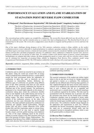
  • 7. IJRET: International Journal of Research in Engineering and Technology eISSN: 2319-1163 | pISSN: 2321-7308 _______________________________________________________________________________________ Volume: 04 Issue: 02 | Feb-2015, Available @ http://www.ijret.org 275 Where, Tmax is the maximum recorded temperature, T3 is the inlet air temperature, T4 is the mean exit temperature, and Tmr is the maximum circumferential mean temperature Table 6. Profile and Pattern Factor for 1300 K Parameter Experimental value Analytical value Percentage Deviation Profile Factor 0.45 0.416 7.55 Pattern factor 2.22 2.011 9.4 The above table 6 shows the comparison of the results with the experimental with the help of two non-dimension numbers Profile Factor and Pattern Factor. 5.2 Three Dimensional SPRF Combustor Analysis Result Property variation in a Stagnation Point Reverse Flow (SPRF) combustor for 1300 K Turbine Entry Temperature (TET) for 3D model was analyzed. The method used for this analysis was Large Eddy Simulation (LES), using which the flame stability and propagation was computed and plotted. It was observed that the pressure loss inside the combustor was found to be less than 5%. The temperature increases gradually and reaches its peak Temperatures and uniformly decreases as the gas propagates out to the Turbine. Temperature is restricted from 1300 K to 1500 K due to material limitations which may account for the damage of the material used for fabrication. In this analysis the combustor was tested only for 1300 K and was found functioning efficiently with stabilized flame propagation. The stability of the flame depends on the length and cone angle of the flame. Velocity increases as the ignition takes place in the combustor, the peak local velocity of around 169 m/s is achieved inside the combustion chamber which gradually decreases at the exit. Velocity will reach zero at the stagnation point and again increases as it reaches the entry of the turbine. 5.2.1 Variation of Different Parameters in Combustor by Varying Inlet Velocities This analysis was carried out without assigning any outlet boundary conditions so that the exact velocity variation across the combustor can be known, and it was observed that there was increase in pressure loss and temperature was also found to be decreasing as the fluid reaches the Turbine Entry Temperature (TET). The contours of the velocity magnitude and its variation across the combustor at the velocity of 90 m/s. Flame was found to be less stable and the velocity reaches to zero at the stagnation point and then uniformly increases to the average value as it reaches the outlet of the combustion chamber. Fig. 7 Contours of Total Pressure
  • 8. IJRET: International Journal of Research in Engineering and Technology eISSN: 2319-1163 | pISSN: 2321-7308 _______________________________________________________________________________________ Volume: 04 Issue: 02 | Feb-2015, Available @ http://www.ijret.org 276 Fig. 8 Contours of Velocity Magnitude Fig. 9 Contours of Static Temperature The above figures show the variation of the flow parameters when Large Eddy Simulation was carried out on the 3-D modeled combustor. This analysis was carried out only by assigning the inlet boundary conditions so that the flame stability is observed. It was inferred that at velocity 120 m/s the flame was stable with minimum decrement in pressure and temperature whereas for velocity 160 m/s flame was found to be unstable and in this case pre-ignition is also seen at the inlet due to high velocities. The pressure loss was found to be more but the Temperature has increased and reaches its peak value of around 1570 K which is considered as very high temperature for the combustor operation in today’s scenario.
  • 9. IJRET: International Journal of Research in Engineering and Technology eISSN: 2319-1163 | pISSN: 2321-7308 _______________________________________________________________________________________ Volume: 04 Issue: 02 | Feb-2015, Available @ http://www.ijret.org 277 6. CONCLUSION Numerical simulations were performed using a commercial CFD code in an attempt to evaluate the performance, mixing and combustion characteristics of the SPRF combustor. In order to determine how the combustor is able to operate stably at very lean conditions and to produce low emissions even in premixed operation. Jet-A as Fuel:  For Jet-A as fuel and for 1300 K of Turbine Entry Temperature (TET) there is very low pressure loss and the maximum pressure achieved is also low. The Temperature variation is less and hence stable operation takes place. Efficient Burning takes place which results in increase in temperature till certain portion and again returns to normal temperatures and it is a restricted flow. It can be inferred that combustor will operate well for low TET’s.  Measurements of the velocity field, Temperature and Pressure in premixed modes show a low average velocity zone with high levels of turbulence in the upper half of the combustor. Based on the geometry of the combustor, this zone is expected to exist over a range of flow conditions (excepted for very low loadings where the flow is laminar and combustion occurs before reaching the stagnation zone). The flame is indeed anchored in this region of high turbulence intensity, and that this is where most of the heat release occurs. This results in an operation of the combustor even at high loadings and very lean equivalence ratios.  Good agreement with analytical solution and experimental observations was obtained in terms of Pattern factor, Profile factor (Table 6) and Flame shape.From the results obtained, the reverse flow combustor can be employed in a small scale engines and also as Gas Turbine Starting Unit, as the increases in inlet air velocity causes pre- ignition, this sets the limit to inlet air velocity.  In summary, the SPRF combustor creates a combination of a low velocity, high turbulence region and the stagnation point and internal product recirculation due to the reverse flow that creates a stable combustion process under a large range of combustor operating conditions. FUTURE SCOPE OF WORK  Detailed measurements of the mixing field have been performed in the SPRF combustor, but the fluid mechanic aspects, like turbulence generation, responsible for this mixing process have not been addressed here. Relative roles of the turbulence generated by various features like shear layer between the opposed streams, the stagnation zone and velocity fluctuations due to the unsteady heat release can be quantified by extending the velocity measurements to a wider range of configurations.  Limiting assumptions should still be listed as base for further work. First, the assumption of adiabatic walls might be refined. In order to capture the possible complex stabilization at the swirled edges, more refined wall temperature modelling as well as a detailed chemical mechanism can be done.  The equivalence ratio oscillation is one of the major sources of heat release fluctuations, and is one of the most important factors determining the characteristics of instabilities. Its effects on combustion dynamics need to be addressed in the future. REFERENCES [1] Bhawan B. Patel and Lorin Markarian “Gas Turbine Engine Reverse-Flow Combustor” Patent No.: US 8,001,793 B2, Date of Patent: Aug. 23, 2011. [2] “Characteristics of Combustion Processes in a Stagnation Point Reverse Flow Combustor”, M. K. Bobba, P. Gopalakrishnan, J. M. Seitzman, B. T. Zinn [3] Mohan K. Bobba “ Flame Stabilization and Mixing Characteristics in a Stagnation Point Reverse Flow Combustor ” ,Georgia Institute of Technology,December 2007 [4] G. D. Myers, T. E. Johnson, S. Maier, S. K. Widener “Reverse-Flow Gas Turbine Combustion System” Patent No.: US 7,966,822 B2 Date of Patent: Jun. 28, 2011. [5] Ying Huang, “Modeling and Simulation of Combustion Dynamics in Lean-premixed Swirl- stabilized Gas-turbine Engines”, The Pennsylvania State University, December 2007. [6] Stephen R. Turns, “An Introduction to Combustion” Concepts and Applications, Department of Mechanical and Nuclear Engineering, The Pennsylvania State University. [7] Arthur H. Lefebvre and Dilip R. Ballal, Third edition “Gas Turbine Combustion”.