
Recommended
Recommended
More Related Content
What's hot
What's hot (6)
More from fjskekdmmmse
More from fjskekdmmmse (20)
Recently uploaded
Recently uploaded (20)
Toyota 6 bws13 electric walkie adjustable straddle stacker service repair manual sn 585890 up
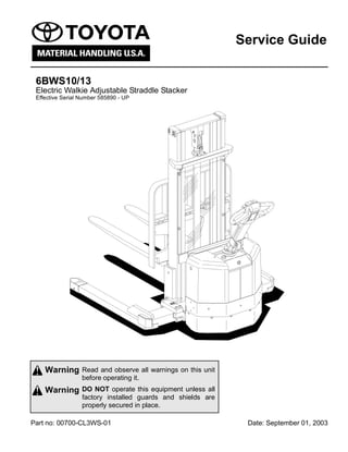
- 1. Read and observe all warnings on this unit before operating it. DO NOT operate this equipment unless all factory installed guards and shields are properly secured in place. Warning Warning Part no: 00700-CL3WS-01 Date: September 01, 2003 Service Guide 6BWS10/13 Electric Walkie Adjustable Straddle Stacker Effective Serial Number 585890 - UP Front Cover
- 2. Table of Contents 1 2003-08-01 Service Guide Parts ordering instructions .......................................................................... 5 Technical Data ............................................................................................... 7 Introduction, Maintenance .......................................................................... 11 Service Program ....................................................................................... 13 Cleaning and Washing .............................................................................. 14 External Cleaning .................................................................................. 14 Motor Compartment Cleaning ............................................................... 15 Electrical Components .......................................................................... 15 Safe Jacking ............................................................................................. 16 Planned Maintenance .................................................................................. 17 Maintenance Schedule ............................................................................. 17 Lubrication Schedule ................................................................................ 22 Oil and Grease Specification ...................................................................... 23 Tools .............................................................................................................. 25 Super Seal Connectors ............................................................................. 25 AMP Connectors ................................................................................... 26 Other Tools ........................................................................................... 27 Support Arm Chassis .................................................................................. 29 General ..................................................................................................... 29 Main Components ..................................................................................... 30 Maintenance ............................................................................................. 30 Support Arm Width Adjustment ................................................................ 31 Support Arm Replacement ....................................................................... 32 Electric Drive Motor ..................................................................................... 35 Component Parts ...................................................................................... 35 Motor Dismantling from Truck ............................................................... 37 Assembling ............................................................................................ 37 Service/Repairs ........................................................................................ 38 Motor Dismantling ................................................................................. 38 Motor Assembling ................................................................................. 39 Cleaning ................................................................................................ 39 Technical Data .......................................................................................... 40 Drive Unit/Gear ............................................................................................. 41 Component Parts ...................................................................................... 42 Technical Data ...................................................................................... 44 Top Cover Leakage .................................................................................. 44 Drive Shaft Sealing Ring Replacement .................................................... 45 Table of Contents
- 3. Table of Contents 2 2003-08-01 Service Guide Electromagnetic Brake ................................................................................ 47 Brake Main Components .......................................................................... 47 Maintenance ............................................................................................. 48 Basic Gap Adjustment ........................................................................... 48 Brake Disc Replacement ....................................................................... 49 Steering ......................................................................................................... 51 Component Parts, Steering (Tiller) Arm .................................................... 51 Brake Microswitch Adjustments ................................................................ 52 Steering (Tiller) Arm Handle ..................................................................... 53 Dismantling/Assembling ........................................................................ 55 Electrical Systems ....................................................................................... 57 Electrical Parts .......................................................................................... 57 List of Symbols and Electrical Wiring Diagram ......................................... 59 Electrical Diagram 1(6) .......................................................................... 61 Electrical Diagram 2(6) .......................................................................... 62 Electrical Diagram 3(6) .......................................................................... 63 Electrical Diagram 4(6) .......................................................................... 64 Electrical Diagram 5(6) .......................................................................... 65 Electrical Diagram 6(6) .......................................................................... 66 Functional Description .............................................................................. 67 Starting the Truck .................................................................................. 67 Driving ................................................................................................... 67 Neutral Speed Reduction ...................................................................... 67 Picture 3 ................................................................................................ 67 Neutral Speed Reduction on Slopes ..................................................... 68 Braking .................................................................................................. 68 Forks Lifting ........................................................................................... 68 Forks Lowering ...................................................................................... 68 Horn ...................................................................................................... 68 Hour Meter ................................................................................................ 69 Fault Codes .............................................................................................. 69 Parameters ............................................................................................... 75 Driver Parameters ................................................................................. 76 Service Parameters ............................................................................... 77 Parameter Description .......................................................................... 78 Part Numbers ............................................................................................ 84 Transistor Panel ........................................................................................ 85 General ................................................................................................. 85 Diagnostic and Troubleshooting ............................................................... 86 Error Codes and Troubleshooting ......................................................... 86 Resetting Errors .................................................................................... 87 Technical Specifications – Curtis 1243 ..................................................... 88
- 4. Table of Contents 3 2003-08-01 Service Guide Hydraulic System ......................................................................................... 89 Hydraulic Diagram and Components ........................................................ 89 Main Components ................................................................................. 90 Description ............................................................................................ 90 Main lift chain system .................................................................................. 91 Checking the chain settings ...................................................................... 91 Chain inspection ....................................................................................... 91 Noise ..................................................................................................... 91 Surface rust ........................................................................................... 91 Rusty links ............................................................................................. 91 Stiff links ................................................................................................ 92 Pin rotation ............................................................................................ 92 Loose pins ............................................................................................. 92 Outline wear .......................................................................................... 93 Stretching .............................................................................................. 94 Damage ................................................................................................. 95 Damaged discs ..................................................................................... 95 Damaged pins ....................................................................................... 95 Dirty chain ............................................................................................. 95 Cleaning .................................................................................................... 96 Lubrication ................................................................................................ 96
- 5. Parts ordering instructions F-code Section C-code Version no T-code 001 5 2003-08-01 Service Guide Parts ordering instructions How to order When you order parts, supply the part number, quantity, model, chassis serial number, and mast serial number of your machine. The serial number on the figure refers to either the Mast serial number or Chassis serial number (see figure below for location of serial numbers) and not the truck serial number (shown on next page). Supplying this information will assure prompt, efficient handling of your order. The pictorial reference number is not needed and including it can only add confusion. Field modifications The regulations imposed by OSHA make it mandatory that alteration of industrial trucks be done only as approved in advance and in writing by the manufacturer. Their regulations apply to counter-weighting, changes in masts when such changes affect capacity and any other safety modifications. It is mandatory that nameplate and instructions be changed accordingly (1910.178 (a)(4)). Toyota will review such changes requested as we can properly evaluate and rerate as to capacity. A change will be Mast Serial Number Chassis Serial Number
- 6. 001 Version no T-code F-code Section C-code Parts ordering instructions 6 2003-08-01 Service Guide evaluated upon receipt of a written request which includes truck and mast serial number and a description of all proposed changes. If the change is approved, authorization will be sent, as will new nameplates or other labeling where appropriate. The new nameplates should be installed over the earlier nameplate. The modifier should send confirmation of the change to the factory along with pictures of the revised truck. Explanation, truck serial number 6BWS10-1 0001 Truck number Capacity (2000lb) Model (6BWS) Straddle Stacker Truck
- 7. Technical Data PS M F-code Section C-code Version no T-code 001 354 7 2003-08-01 Service Guide Technical Data Model 6BWS10/13 Drive Motor Type TSL140S-DS30 Output, hp (kW) 1.6 (1.2) Duty cycle S2, 60 min Minimum carbon brush length, inch (mm) 0.5 (13) Nominal commutator diameter, inch (mm) 2 (50) Minimum commutator diameter, inch (mm) 1.85 (47) Resistance, shunt field winding, Ω at 77° F (25° C) 0.49 Resistance armature winding, Ω at 75° F (24° C) 0.0156 Insulation resistance between the windings and motor casing >=1 Mohm Weight, lb (kg) 30 (14) Brakes Type BFK457-08 Braking force, ft-lbs (N•m) 8.85 (12) Output, W 25 Resistance coil, Ω 23 Nominal play in actuated position, inch (mm) 0.078-0.157 (0.2-0.4) Minimum thickness brake disc, inch (mm) 0.216 (5.5) Thickness of a new brake disc, inch (mm) 0.275 (7.0) Transmission/Drive Gear Type 2-stage angle transmission Gear ratio 19,14:1 Oil volume, gallon (liter) 0.26 (1.0) Oil type at normal temperature at temperature < 5° F (-15° C) Hypoid oil SAE 80W/90 SAE 75W
- 8. PS M 001 354 Version no T-code F-code Section C-code Technical Data 8 2003-08-01 Service Guide Wheels Drive wheel, inch (mm) Dia 8.5 x 3 (215 x 70) Axle pressure without load, lbs (kg) 1521 (690) Axle pressure at rated load, lbs (kg) 1620 (735) Tightening torque for wheel bolts, ft-lbs (N•m) 47 (65) Support arm wheel, inch (mm) Dia 14 x 3 (100 x 75) Axle pressure without load, lbs (kg) 2 x 355 (240) Axle pressure at rated load, lbs (kg) 2 x 1510 (240) Hydraulic System Output, hp (kW) 2.95 (2.2) Duty cycle,% 5 Minimum carbon brush length, inch (mm) 0.5 (12) Minimum commutator thickness/diameter, inch (mm) 0.187 (4.75) Pressure at rated load, psi (bar) 2800 (193) Overflow pressure, psi (bar) 3046 (210) Pump flow, gpm (liter/minute) 1.32 (5.0) Tank volume, gpm (liter/minute) 1.19 (4.5) Oil type: at normal temperature at temperature < 5° F (-15° C) Hydraulic oil ISO-L-HM32 ISO-L-HV32 Fuses Drive motor circuits, A 125 Pump motor circuits, A 125 Control circuits, A 7.5 Battery Compartment, Batteries Dimensions LxWxH, inch (mm), 180 Ah 240 Ah 320 Ah 7.72 x 25.31 x 17.80 (196 x 643 x 452) 7.72 x 25.31 x 22.52 (196 x 643 x 572) 9.60 x 25.31 x 22.52 (244 x 643 x 572) Capacity, Ah 180-255 Weight, lbs (kg) 290-600 (131-272) Model 6BWS10/13
- 9. Technical Data PS M F-code Section C-code Version no T-code 001 354 9 2003-08-01 Service Guide Driving Speed Without load, 0-750 kg, m/h (km/h) 3.73 (6.0) With rated load, m/h (km/h) 3.29 (5.3) Lift/Lowering Speed Lift without load, f/s (m/s) 6.7 (0.19) Lift with rated load, f/s (m/s) 3.5 (0.10) Lowering without load, f/s (m/s) 5.3 (0.15) Lowering with rated load, f/s (m/s) 6.7 (0.19) Power Consumption Driving without load, A 23 Driving with rated load, A 34 Lift without load, A 54 Lift with rated load, A 148 Incline Climbing Ability With rated load 8% Turning radius Turning radius WA, inch (mm) 60 (1519) Weight Truck without battery, (medium) lbs (kg) With mast 83/128 [2108/3251 mm] 1686 (765) Model 6BWS10/13
- 10. Introduction, Maintenance PS M F-code Section C-code Version no T-code 001 354 11 2003-08-01 Service Guide Introduction, Maintenance Safety Regulations with Maintenance Work Only authorized personnel that have been trained in the service and repair of this type of truck should carry out service and repair work. • Do not carry out any maintenance work on the truck unless you have the correct training and knowledge to do so • Keep the area clean where you carry out the service. Oil or water makes the floor slippery • Do not wear watches, rings, or jewelry when working on the truck • Avoid wearing loose-fitting clothing • Wear personal protection equipment to protect eyes, face, and skin • Use insulated tools • Always disconnect the battery by pulling out the battery isolator when carrying out maintenance work on the truck unless otherwise stated in this Service Manual • Always switch off the truck’s power supply before opening the covers on the drive unit or electrical system • Relieve the system pressure slowly before starting work on the truck’s hydraulic system • Use paper or a rigid sheet of cardboard when checking for oil leakage. Never use your hand Short-circuiting/Burns. When working with the truck’s electrical system, short-circuiting/burns can occur if a metal object comes into contact with live electrical connections. Remove watches, rings or other types of metal jewelry. WARNING
- 11. PS M 001 Version no T-code F-code Section C-code Introduction, Maintenance 12 2003-08-01 Service Guide • Bear in mind that the oil in the transmission or the hydraulic system can be hot • Store and dispose of changed oil in accordance with local directives • Do not release solvents and the like, which are used for cleaning/washing, into drains that are not intended for this purpose. Follow the local directives that apply for disposal • Disconnect the battery when welding on the truck Risk of burns. Hot transmission and hydraulic oil. Let the truck cool before changing the oil. Only fill the hydraulic system with new and clean oil The hydraulic system can be damaged. If the oil is contaminated, hydraulic components can be damaged. Always use new and clean oil in the hydraulic system. NOTE! The battery can be damaged. When welding using an electric power source, the welding current can enter the battery. The battery should therefore be disconnected. Harmful gases. Paint that is heated gives off harmful gases. Remove 4.0 inches (100 mm) of paint from the work area. WARNING WARNING CAUTION
- 12. Introduction, Maintenance PS M F-code Section C-code Version no T-code 001 354 13 2003-08-01 Service Guide • Remove at least 4.0 inches (100 mm) of paint around the welding/grinding area through sand-blasting or the use of a paint stripper when welding or grinding on painted surfaces 1. Service Program All points in the service program should be carried out to attain proper operation and the least possible downtime. The service intervals are only a guide and do not need to be followed to the letter. They may be adapted to local conditions, but it is important that the intervals comply with Toyota’s minimum requirements. The service intervals are based on the running times and can be adapted to most normal 8 hour shifts. The service interval may be shortened if the truck is used more frequently or in more demanding situations, such as cold store, dusty or corrosive situations. The following running times have been used when calculating the intervals: - Single shift operation: 20 hr./week - 2-shift operation: 40 hr./week - 3-shift operation: 60 hr./week Ensure the truck is given a regular maintenance service after every 500 driving hours. The truck’s safety, efficiency and service life is dependent on the service and maintenance it is given. Only use Toyota approved spare parts when service and repair work are carried out.
- 13. PS M 001 Version no T-code F-code Section C-code Introduction, Maintenance 14 2003-08-01 Service Guide 2. Cleaning and Washing Cleaning and washing of the truck is important to ensure the truck’s reliability. • Carry out general cleaning and washing weekly 2.1 External Cleaning • Remove rubbish, etc. from the wheels daily • Use a well-known degreasing agent, diluted to a suitable concentration • Rinse off loose grime using tepid water NOTE! Risk of short-circuiting. The electrical system can be damaged Disconnect the battery before washing by pulling out the battery connector. NOTE! Jamming, corrosion. Mechanical components can be damaged. After washing, the truck should be lubricated as set out in the “Maintenance Schedule” on page 17 and “Lubrication Schedule” on page 22.
- 14. Introduction, Maintenance PS M F-code Section C-code Version no T-code 001 354 15 2003-08-01 Service Guide 2.2 Motor Compartment Cleaning • Cover the electric motors, connections and valves before washing • Clean the motor compartment using a well-known degreasing agent, diluted to a suitable concentration • Rinse off loose grime using tepid water 2.3 Electrical Components • Blow electric motors down using compressed air • Clean the electrical panels, electronic boards, contactors, connections, solenoid valves, etc. using a damp cloth and a cleaning agent NOTE! Risk of short-circuiting. The electrical system can be damaged. Electrical components must not be cleaned with a high pressure washing unit. When using compressed air, wear effective chip-guarding and personal protective equipment. Compressed air used for cleaning MUST be reduced to less than 30 psi (207 kPa). NOTE! Risk of short-circuiting. Electrical components can be damaged. Do not break the guarantee seal on the electronic board. WARNING
- 15. PS M 001 Version no T-code F-code Section C-code Introduction, Maintenance 16 2003-08-01 Service Guide 3. Safe Jacking All lifting must be carried out on a flat, non-slip and firm surface. Avoid new laid asphalt or asphalt on a hot summer’s day. • Activate the parking brake to prevent the truck from moving during the lift. If the lift applies to the brake wheel, chock the other wheels so that the truck stands still • Select a lifting point so that the lift is as easy as possible (one corner at a time). If the truck has marked lifting points on the under side of the chassis these can be used to obtain a well balanced lift • Ensure that the surface under the jack is clean and free from oil and grease • Ensure that your hands and the jack’s lever are free from oil and grease • Use the lever that belongs to the jack. A lever that is too short requires more force than is necessary. If the lever is too long there is a risk of the jack being overloaded • Support the truck: - as close as possible to the part of the chassis that is to be lifted. This reduces the risk of the truck tipping over - so that the truck cannot roll • Never lift up the jack in order to lift higher • Never work under a lifted truck unless it is well supported Risk of crushing. A badly supported truck can fall. Never work under a truck that is not supported on trestle-blocks and secured by a lifting device. WARNING
- 16. Planned Maintenance PS M F-code Section C-code Version no T-code 001 354 17 2003-08-01 Service Guide Planned Maintenance 1. Maintenance Schedule I: Inspect, rectify and change if necessary. T: Tighten. C: Clean. L: Lubricate. M: Control measurement, rectify if necessary Pos. No. Work to carry out Interval in hours - may vary due to application 5 20 80 500 1000 3000 Interval in days/weeks/months - may vary due to application 1d 1w 1m 6m 12m 36m 0000. Chassis 0000.1 Check all links and locking pins I 0000.2 Check wear on cover/battery locking I 0000.3 Check of cracking and damage I 0000.4 Check the drive housing’s mounting on the chassis T 0000.5 Check finger guard I 0000.6 Check signs and stickers I 0380. Fork Carriage 0380.1 Check for crack formation and damage I 0380.2 Check clearance in bushes and links I 1700. Drive Motor 1700.1 Check clearance in connections I/T1 I/T 1700.2 Check the carbon brushes in the drive motor M 1700.3 Clean the drive motor C 1700.4 Re-tighten the attachment bolts T2 1700.5 Check for abnormal noise in bearing I
- 17. PS M 001 354 Version no T-code F-code Section C-code Planned Maintenance 18 2003-08-01 Service Guide 2550 Drive Gear 2550.1 Check for leakage I3 I 2550.2 Check the oil level. Use the screwed in dipstick to measure oil I 2550.3 Check for abnormal noise I 2550.4 Check the attachment and clearance in steering bearing I 2550.5 Change the oil in the drive gear L4 L 3100. Brake 3100.1 Clean and check functionality C 3100.2 Check the brake disc M 3100.3 Check the clearance in disengaged position 0.0078-0.02 inch (0.2-0.5 mm) M 3500 Wheels 3500.1 Remove string and other rubbish I 3500.2 Check the drive wheel for wear and the tightening torque on bolts (New wheel: Drive tread thickness = 1.18 inch [30mm]) (Tightening torque = 48 ft-lbs [65 N•m]) I/T 3500.3 Check that the caster wheel turns and rotates freely I 3500.4 Check for wear on the caster wheel (New wheel: Drive tread thickness = 0.40 inch [10 mm]) I 4110 Steering (Tiller) Arm 4110.1 Check the mountings I 4110.2 Check the power in the gas damper I 4110.3 Check steering I I: Inspect, rectify and change if necessary. T: Tighten. C: Clean. L: Lubricate. M: Control measurement, rectify if necessary Pos. No. Work to carry out Interval in hours - may vary due to application 5 20 80 500 1000 3000 Interval in days/weeks/months - may vary due to application 1d 1w 1m 6m 12m 36m
- 18. Thank you very much for your reading. Please Click Here. Then Get COMPLETE MANUAL. NO WAITING NOTE: If there is no response to click on the link above, please download the PDF document first and then click on it.
- 19. Planned Maintenance PS M F-code Section C-code Version no T-code 001 354 19 2003-08-01 Service Guide 5000 Electrical Functions 5000.1 Check the function of the brake microswitch I I 5000.2 Check the function of the reverser switch I 5000.3 Check the function of the horn I I 5000.4 Check for wear to cables in the steering (tiller) arm I 5000.5 Check the function of the driver’s control I I 5000.6 Check the error code log and operating times I I 5110 Battery 5110.1 Check the electrolyte level, 0.40-0.60 inch (10-15 mm) over the cell plates M 5110.2 Check connections to battery, truck and charger I 5110.3 Check that the cell and pole guards are undamaged I 5110.4 Check the fluid density and temperature M 5110.5 Remove overflow fluid from the battery trough C 5110.6 Check the battery locking I 5400 Power System 5400.1 Cleaning and checking of mounting in chassis C/T1 C/T 5400.2 Re-tighten cable connections T1 5400.3 Check the contactor points on K10 and K30 I 5400.4 Check the movement of the contactors I 5400.5 Check the cable insulation I I: Inspect, rectify and change if necessary. T: Tighten. C: Clean. L: Lubricate. M: Control measurement, rectify if necessary Pos. No. Work to carry out Interval in hours - may vary due to application 5 20 80 500 1000 3000 Interval in days/weeks/months - may vary due to application 1d 1w 1m 6m 12m 36m
- 20. PS M 001 354 Version no T-code F-code Section C-code Planned Maintenance 20 2003-08-01 Service Guide 1 = The connections are re-tightened for the first time after 80 h, and then every 1000 h/12 months. 2 = The attachment bolts are re-tightened after 80 h/ 1 month to 33 ft-lbs (45 N•m). 3 = Check for leakage in conjunction with the first oil change. 4 = The oil is changed for the first time after 80 h/1 month, and then every 3000 h/36 months 5 = The oil is changed and the filter cleaned for the first time after 80 h/1 month, and then every 1000 h/12 months 5700 Electronic Circuit Board 5700.1 Check connectors and cables T1 5700.2 Check all segments on display I 6000 Hydraulic System 6000.1 Check hoses and connections for leakage I 6000.2 Check hoses for wear and damage I 6000.3 Check the oil tank for cracks, leakage and damaged mountings I 6000.4 Check that the oil level is correct I I 6100.5 Change the oil and clean the filter L5 L 6600 Lift Cylinder 6600.1 Check for leakage I 6600.2 Check the mountings I 7100 Lifting Mast 7100.1 Check for damage and crack formation I 7100.2 Retighten the mast mounting bolts (Tightening torque = 145 ft-lbs [197 N•m]) T 7100.3 Check the play of the inner section rollers I X 7100.4 Check the lateral play of the inner section I X 7100.5 Check for wear on the lifting chains and chain rollers I X 7100.6 Check the adjustment of the lifting chains I X I: Inspect, rectify and change if necessary. T: Tighten. C: Clean. L: Lubricate. M: Control measurement, rectify if necessary Pos. No. Work to carry out Interval in hours - may vary due to application 5 20 80 500 1000 3000 Interval in days/weeks/months - may vary due to application 1d 1w 1m 6m 12m 36m
- 21. Planned Maintenance PS M F-code Section C-code Version no T-code 001 354 21 2003-08-01 Service Guide When points with higher hour intervals are carried out, the points with lower hour intervals should also be carried out unless otherwise specified. 4110 7100 6600 0380 5110 5400 2550 3500 6000 3100 5000 5700 0000 1700