MS4 level being good citizen -imperative- (1) (1).pdf
Railway rectification
1. Rectifiers for railway-traction substations
F. T. Bennell
Indexing terms: Railways, Rectifier substations, Solid-state rectifiers, Traction
Abstract: This is a general review of the present state of development of silicon rectifier equipment for the
supply of d.c. for railway traction. Current general practice is described and reference is made to the latest
developments, including compensators for paralleling double-bridge rectifiers, and capsule diodes.
1 Introduction actance of 10%, and the resultant short-circuit current
D.C. supplies to railways are provided by rectifier equip- would be a nominal ten times full load.2
ment in substations distributed along the track. The basic With a common transformer and two secondary windings
requirements have remained the same, dating back to the the required reactance is 10% for the load of each second-
mercury-arc era,1 but, particularly since the advent of ary, the other bridge circuit involving the other secondary
silicon-diode rectifiers, there has been, and continues to be, not commutating at the same time. This gives a nominal
substantial progress in rectifier equipment design. 20%* if the load on this one secondary is increased until
full primary current is taken, this being the way reactance
The direct voltages commonly in use are nominally
is measured for the determination of d.c. regulation. Hence,
750 V, 1500 V and 3000 V. The voltage level affects the
the relationship that the percentage regulation is a nominal
balance of factors that determine the optimum basic design.
0-25* times the percentage reactance for 12-pulse operation
The 750 V level is the most widely used and this paper is
compared with 0-5 times for 6-pulse.
written generally for this, with references to variations
arising from the use of higher voltages. Short circuit involves both secondary windings, hence
The simplest form of circuit for this duty is a 3-phase short-circuit current depends upon the total reactance. If
bridge, giving 6-pulse rectification. Its main disadvantage the secondary windings are not magnetically coupled, i.e.
is the relatively high ripple in the d.c. at six times funda- do not share the same flux, the reactance with both second-
mental frequency, increasing from about 4% r.m.s. at no aries short-circuited decreases nominally to a half, due to
load to, typically, 6% at full load and higher for overloads, doubling the flux linkages between primary and secondary
due to increasing overlap. This can cause interference with by involving the second secondary winding, making the re-
signalling circuits which are running in parallel in close actance a nominal 10%. If, however, the secondary windings
proximity along the same route. The 5th and 7th harmonic are closely coupled they occupy the same envelope volume
whether one or both are involved and the reactance is the
currents drawn from the supply by 6-pulse rectifiers are
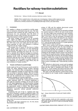
same for both conditions, i.e. nominally 20%, and the short-
also undesirable as, in addition to other effects, they can
circuit current is nominally only 5 times full load, as shown
cause unbalance in 12-pulse rectifiers.1'3
in Fig. 1.
2 12-pulse rectification by parallel bridges This reduction in short-circuit current and its resultant
rate of rise are a considerable help in enabling the rectifier
6-pulse ripple and 5th and 7th harmonics can be avoided by diodes and their fuses to withstand short circuits. It also
having two phase displaced 6-pulse rectifiers operating helps the d.c. circuit breakers and reduces the stress on the
together, the combined effect corresponding to 12-pulse equipment and the damage where the short circuit occurs.
rectifier equipment, provided of course both sets of equip- The point is that this reduction in short-circuit current
ment are always in operation together. This can be devel- is not achieved by all 12-pulse rectifier arrangements but
oped further by combining the equipment into a common
bank and the transformers into a common tank, or two
secondary windings on a common transformer.
A combined rectifier giving 12-pulse operation can have
another important effect. If a common transformer is
used, with two secondary windings, one star and one delta
for a 30° phase displacement, and these secondary windings
are closely coupled, for the same direct voltage regulation
the short-circuit current is halved. This merits careful
explanation as it is a point that has been brought up in IEE
discussions, apparently without generally understood
clarification.
Considering that part of the d.c. regulation (the main
part) due to reactance, a rectifier is required to have a 5% Fig. 1 Output characteristics of 6-pulse and 12-pulse rectifiers
regulation, for example 750 V on full load and 789 V on no a 12-pulse
load. An individual 6-pulse rectifier would require a re- b 6-pulse
Paper T298 P, first received 14th September and in revised form 26th Strictly speaking, 19-3% and 0-259, respectively, as the cancel-
October 1978. lation of the 5th and 7th harmonics in the primary winding reduce
Mr. Bennell is with Foster Transformers Ltd., The Path, Morden the primary current and kVA on which the percentage reactance
Road, London, SW19 3BN, England. is based, by 3-4%.
22 ELECTRIC POWER APPLICATIONS, FEBRUARY 1979, Vol. 2, No. 1
0140-1327/79/010022 + 05 $01-50/0
2. only when the two transformer secondary windings are by 3-4%. The transformer secondary kVA and transformer
closely coupled in a common flux circuit. losses are correspondingly reduced.
Associated with this desirable effect is, however, a (e) The conducting period in each rectifier arm is
design difficulty. To the extent that the leakage flux and increased from 120° plus overlap to 150° plus overlap, thus
therefore reactance is common to the two secondary reducing the form factor of the current and that part of the
windings it does nothing towards influencing current diode losses associated with the slope resistance (see typical
sharing between them. The current sharing is determined manufacturer's diode-rating curves).
only by that part of the reactance that is individual to the The compensator itself is somewhat larger in rating
respective secondary windings and by their individual than the interphase transformer it displaces. However,
resistances. It may, therefore, be substantially out of there is usually an appreciable depth of oil in the trans-
balance and readily upset by supply harmonics. Careful former tank between the top of the transformer and the
design is necessary to keep these effects within satisfactory oil level and the compensator can go there without adding
limits.4 appreciably to the tank dimensions.
If there is an individual transformer for each rectifier
3 Current balancing compensator bridge, or if the transformer secondary windings are end to
end and therefore have no appreciable flux coupling, it is
A recent development is the introduction to parallel bridge possible to omit the interphase transformer without adding
rectifier circuits of a compensator to ensure equal current a compensator. This also avoids the problem of critical
sharing,4 as shown in Fig. 2. The compensator has the conditions for current sharing. It may be practical in some
following virtues: cases to do this and indeed it is done. However, the short-
(a) In otherwise unfavourable conditions for good circuit current is then about double what it would be for
current sharing the current is shared equally between the the close coupling.
two rectifier bridges over the complete current range.
(b) The interphase transformer, which is in the d.c.
circuit and therefore normally fitted in the rectifier cubicle
4 Cooling
assembly, is an awkward component to accommodate, and
tends to be a nuisance in respect of the noise it makes, The diodes are mounted on heat sinks, which are generally
operating at six times the fundamental frequency. The of extruded aluminium and invariably air cooled. Natural
necessity for an interphase transformer is avoided by the convection is preferable as the equipment is then completely
use of the compensator. static, and no warning or tripping circuits are necessary as
(c) The compensator, being in the a.c. circuit, goes a protection against fan failure.
under oil in the main transformer tank. Sometimes, however, it is left open to the manufacturer
(d)12-pulse operation and current waveforms are to use either forced or natural cooling, and the contract
obtained in the individual bridges. The 5th and 7th har- goes to the lowest bidder. This is undesirable as, although
monics normally present in the transformer secondary there is not a great difference in cost, a forced-air-cooled
windings are eliminated, reducing the total r.m.s. current rectifier may be marginally cheaper. A minor difference in
price should not outweigh a major difference in simplicity
and reliability.
A When there is sufficient diode capacity to deal with
short-circuit conditions, cooling is not then a difficult
problem and the saving in heat sinks and size of equipment
is largely offset by the cost of fans and their protection
rfl
circuits.
transformer
V Natural cooling is now normal in substation applications.
t
5 Diodes
compensator
L L Diode development has kept up with the requirements for
substation duties. In respect of voltage rating, peak ratings
of 2kV are adequate for bridge-connected rectifiers in
750 V d.c. systems and 4kV peak ratings for 1500 V
systems. Series connections of diodes are used for higher
voltages than these, or 1500 V conversion rectifiers where
mercury-arc rectifiers were originally used in single-way
connection.
•fcM As diode-voltage ratings increase, thicker silicon slices
• * •
are necessary; the forward diode losses increase and the
fault-current ratings are reduced. In this situation there is a
•£+ temptation to use lower voltage diodes than are really
desirable. This is something that should be controlled by
national standards or user specifications. USA specifications
ANSI C34 and NEMA R9 appear to require, for this duty,
a voltage safety factor of 2-5, without being sufficiently
clear about it as to ensure that it is complied with. No
Fig. 2 Compensator in a parallel-bridge rectifier British Standard covers this point. 2-5 is a figure that, to a
ELECTRIC POWER APPLICATIONS, FEBRUARY 1979, Vol. 2, No. I 23
3. degree, is arbitrary; perhaps further experience since the overcome difficulties in the satisfactory application of
publication of the US specifications would justify this capsule diodes:
being reduced to 2-25. These remarks assume adequate (a) The diodes are clamped between pairs of heat sinks
conventional capacitance/resistance transient overvoltage in banks of six. This gives a high degree of compactness.
protection. (b) The disc spring clamping assemblies project from the
Current ratings are basically determined by silicon- main rectifier enclosure and are accessible for visual
slice diameters. Those in service for this duty go up to checking of pressure and adjustment without opening the
50mm diameter and 76mm diameter is available. Diodes rectifier enclosure.
with 38 mm silicon diameter are in general use in British (c) The series clamping gives equal clamping pressure for
equipment. These are base mounting, and therefore single- all the diodes in the stack.
side cooled, and are about the maximum size that can be (d) The diodes are carried in removable cards which on
usefully used with single-side cooling, although base- unclamping can be removed like books from a bookshelf.
mounting diodes with 50 mm silicon have been produced. (e) The diode cards are designed to completely enclose
the diodes for dust protection and externally to provide a
6 Capsule diodes barrier between the poles.
(/) There is no need to remove heat sinks to replace a
Capsule-type diodes for clamping between two heat sinks
diode.
have many advantages:
(g) Connection is inherent in the clamping, so there is no
(a) Obviously there are two heat sinks per diode instead
undoing of connections involved, as such.
of one.
The only problem during assembly was that, since diode
(b) Less obviously but perhaps even more important, the
replacement was so easy, it was difficult to prevent its
junction to case internal thermal resistance is halved for the
continual demonstration. However, the balance of advan-
same current and power, as shown in Fig. 3.
tage was restored when in test it was discovered that all
(c) The variety of mounting bases and top terminal
diodes had been put in the wrong way round and it took
connections is eliminated and the various makes are physi-
only half an hour to put this right. The design now incor-
cally interchangeable.
porates locating features such that the diodes can only be
(d) Capsule diodes are the same for either polarity.
correctly fitted.
There are two factors that have delayed the more general
use of capsules. One is that they are not so easy to mount
as base-mounting diodes, the clamping requirements being
more critical and the spring loading has to be external outside
the heat sinks. The second is that the optimum economics
of manufacture will not be achieved until they are required
in the same numbers as the common base-mounting diodes,
and production is as well developed and established. How-
ever, the design advantages become overriding for the larger
silicon diodes now available.
7 Capsule diode rectifier in service
Equipment with double-sided cooled capsule diodes has
now been in service in the UK for several years. It is shown
in Fig. 4 and incorporates several novel features designed to
junction
155°C
pole peices
100t
base Fig. 4 1500kW 12-pulse rectifier equipment with readily checked
100°C and removed capsule diodes with double-sided cooling
junction Reproduced by courtesy of London Transport
128°C
8 Single-diode design
630A, 850W 630A,2xA25W
A further consequence of the capsule development is the
base mounting diode
100 C ability to use just one large diode in each rectifier arm.
single-sided cooled
Single diodes are available for rectifiers up to about
1500 kW. While cooling is the most difficult aspect, such a
155C
rectifier has been made and is now in service. It is 12-pulse,
comprising parallel bridges and has a rating of 1500 kW (see
1000A, 2x85OW Fig- 5).
capsule type diodes This development radically changes the design consider-
double sided cooled ations. When diodes are used in parallel there is a current-
Fig. 3 Comparison of diode temperatures for single-sided and sharing problem. Their forward voltage drops must lie
double-sided cooling for the same mounting surface temperature within close limits and a substantial out-of-balance current
Arrows indicate heat flow is allowed for in their rating. If a diode fails, and is taken
24 ELECTRIC POWER APPLICATIONS, FEBRUARY 1979, Vol. 2, No. 1
4. out of operation by its fuse, this is not directly apparent 9 Diode failure indication
and an indicating system is therefore required.
Diode fuses are used to take out any diode which fails, Early silicon rectifier equipment had many protective
enabling the remainder to carry on working. A failed diode features, some of which have been found by experience
short-circuits the transformer and there is a possibility that not to be necessary, but are still specified. A case in point
in unfused applications a diode may explode if it cannot is provision for a warning to be given in the event of one
carry the fault current until it is cleared by the a.c. switch- diode failure, and tripping if two diodes fail in any arm.
gear. This, of course, is quite inappropriate in the case of traction
rectifier equipment since to cope with a heavy load all
available rectifiers should be kept operational. A warning
may be helpful so that the number of trains and the
number of operational rectifiers may be kept compatible.
However, as rectifier diodes for this duty are very un-
likely to fail, such systems are superfluous and only reduce
the reliability of the complete equipment. The major
British users have from the beginning kept to a simple
visual indication of diode-fuse operation and their ex-
perience has proved this to be sound.
10 Series bridges
For 1500V equipment it becomes reasonable to have
phase-displaced rectifier bridges in series for 12-pulse
operation. No interphase transformer is necessary and the
two bridges being in series carry equal currents. The only
disadvantage is that compared with parallel bridges there
are twice as many diodes, heat sinks and fuses. However,
the diodes and fuses are of lower voltage and the losses
per diode are less. Fig. 6 illustrates a 1500 V rectifier
Fig. 5 1500kW 12-pulse rectifier equipment with single diode per incorporating series bridges.
rectifier arm
Reproduced by courtesy of London Transport 11 Conclusions
It is gratifying to note that the UK has played a major
The diodes used in the single-diode rectifier referred to
part in the development of rectifier equipment for this
are rated to carry the short-circuit current until the a.c.
duty, both at home and abroad. The following features
switchgear opens. There is therefore no need for diode
have been actively promoted by British manufacturers:
fuses, and while the rectifier is operational there is no need
(a) natural current sharing between diodes where
to check whether any diode has failed.
previously forced current sharing by compensators had
A number of points which have been accepted practice
been specified
in the design of rectifiers for this duty need rethinking.
When there are a number of diodes in parallel it is quite
easy and economic to have one extra in each arm, so that
the rectifier can carry on working with one failure. But
with a rectifier designed to operate with only one diode per
arm, an extra diode doubles the rectifier capacity.
In this respect this is a return to the situation with
mercury-arc rectifiers. Because they were substantial items,
an extra bulb was not normally included to take care of the
possibility of a failure. There may have been extra complete
rectifier equipment to provide spare capacity, but where
this was the practice with mercury-arc rectifiers a similar
number of silicon rectifiers are now installed.
In this, there are the factors of reliability and the need
for maintenance. Mercury-arc rectifiers gave good service
for many years but they had a tendency to blow their fuses
when suddenly taking a heavy load in cold weather and the
bulbs or tanks occasionally needed replacing or reprocessing.
Silicon diodes do not really need any maintenance, replace-
ment or reprocessing. Experience has shown that, provided
there is nothing wrong with the basic design of silicon
rectifier equipment, failure of silicon diodes is virtually
unknown.
The point is that with the use of silicon diodes instead Fig. 6 1500kW 1500 V 12-pulse rectifiers comprising series
of mercury-arc rectifiers the need for standby features is bridges. 3 equipments being installed at Gosforth substation, Tyne
not increased but reduced, and spare diodes, when there are and Wear Metro
only one two or three in parallel, are not justified. Reproduced by courtesy of Tyne and Wear PTE
ELECTRIC POWER APPLICATIONS, FEBRUARY 1979, Vol. 2, No. 1 25
5. (b) natural convection cooling 12 References
(c) 12-pulse operation with reduced short circuit currants , , . . . _ . n t, , i w i x t ~. o n Ar . „ tw
) , • i • , . i. x- /• J- , c • 1 MARTI, O. K., and WINOGRAD, H.: Mercury arc power
(d) simple visual indication of diode fuse operation rectifiers' (McGraw-Hill, 1930)
instead of microswitches, resistors, transistor circuits and 2 SCHAEFER, J.: 'Rectifier circuits' (Wiley, 1965)
small wiring in the main circuit rectifier assembly 3 READ, J. C: 'Calculation of rectifier and inverter performance
(e) capsule diodes with double-sided cooling, culmi- characteristics',/./^, 1945, 92, Pt. II, P P 495-509
x. • • i J. j x-f 4 BENNELL, F. T.: 'Current balance in 12-pulse rectifiers com-
nating in a single diode per rectifier arm p r i s i n g p a r a M b r i d g e s , 5 in T o w e r e i e c t r o n i c s _ P o w e r s e m i -
( / ) compensators for parallel bridge circuits, without conductors and their applications', IEE Conf. Publ. 154, 1977,
interphase transformers (protected by patent). pp. 66-69
26 ELECTRICPOWER APPLICATIONS, FEBRVARY 1919, Vol. 2, No. 1