

Recommended
More Related Content
What's hot
What's hot (20)
Similar to Lab mannual ncert 3
Similar to Lab mannual ncert 3 (20)
More from Himani Asija
More from Himani Asija (14)
Recently uploaded
Recently uploaded (20)
Lab mannual ncert 3
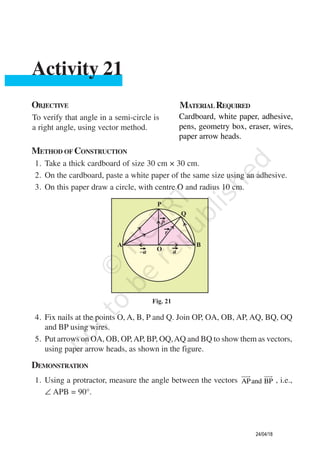
- 1. METHOD OF CONSTRUCTION 1. Take a thick cardboard of size 30 cm × 30 cm. 2. On the cardboard, paste a white paper of the same size using an adhesive. 3. On this paper draw a circle, with centre O and radius 10 cm. OBJECTIVE MATERIAL REQUIRED To verify that angle in a semi-circle is a right angle, using vector method. Cardboard, white paper, adhesive, pens, geometry box, eraser, wires, paper arrow heads. Activity 21 4. Fix nails at the points O, A, B, P and Q. Join OP, OA, OB, AP, AQ, BQ, OQ and BP using wires. 5. Put arrows on OA, OB, OP,AP, BP, OQ,AQ and BQ to show them as vectors, using paper arrow heads, as shown in the figure. DEMONSTRATION 1. Using a protractor, measure the angle between the vectors APand BP , i.e., ∠ APB = 90°. 24/04/18
- 2. 158 Laboratory Manual 2. Similarly, the angle between the vectors AQand BQ , i.e., ∠ AQB = 90°. 3. Repeat the above process by taking some more points R, S, T, ... on the semi-circles, forming vectors AR, BR; AS, BS; AT, BT; ..., etc., i.e., angle formed between two vectors in a semi-circle is a right angle. OBSERVATION By actual measurement. OP OA OB OQ r a p= = = = = = = _______ , AP = _______ , BP = _______, AB = ______ AQ = _______ , BQ = _______ 2 2 AP BP+ = ________, 2 2 AQ BQ+ = ________ So, ∠APB = ________ and AP.BP ________ ∠AQB = ________ and AQ.BP = ________ Similarly, for points R, S, T, ________ ∠ARB = ________, ∠ASB = ________, ∠ATB = ________, ________ i.e., angle in a semi-circle is a right angle. APPLICATION This activity can be used to explain the concepts of (i) opposite vectors (ii) vectors of equal magnitude 24/04/18
- 3. Mathematics 159 (iii) perpendicular vectors (iv) Dot product of two vectors. NOTE Let OA = OB = a = OP = p OA – a= , OB a= , OP p= AP – OA OP a p= + = + ., BP –p a= . ( ) ( ) 2 2 AP. BP . – – 0p a p a p a= + = = . ( )2 since p a= So, the angle APB between the vectors AP and BP is a right angle. Similarly, AQ. BQ 0= , so, ∠AQB = 90° and so on. 24/04/18
- 4. METHOD OF CONSTRUCTION OBJECTIVE MATERIALREQUIRED To locate the points to given coordinates in space, measure the distance between two points in space and then to verify the distance using distance formula. Drawing board, geometry box, squared paper, nails of different lengths, paper arrows. Activity 22 –5–6 –3–4 –1–2 21 43 65 –1 –2 –3 –4 –5 –6 1 2 3 4 5 6Z C M S D A L O B N (–2, 2) (4, 1, 3) (4, 1) (3, –5) (–2, –3) (–2, –3, 1) Y X 2 cm 3 cm 4 cm 1 cm (–2,2,2) (3, –5, 4) X¢ Y¢ Fig 22 24/04/18
- 5. Mathematics 161 1. Take a drawing board and paste a squared paper on it. 2. Draw two lines X′OX and Y′OY to represent x-axis, y-axis respectively (see Fig. 22) and take 1 unit = 1 cm. 3. Fix a wire through O, in the vertical direction, representing the z-axis. 4. Fix nails of length 1 cm, 2 cm, 3 cm, 4 cm, etc. at different points on the squared paper (say at L (–2, –3), N (–2, 2), M (4, 1), S (3, –5)), etc. Now the upper tips of these nails represent the points (say A, B, C, D) in the space. DEMONSTRATION 1. Coordinates of the point A = (–2, –3, 1). 2. Coordinates of the point B = (–2, 2, 2). 3. Similarly find the coordinates of the point C and D. 4. By actual measurement (using a scale) distance AB = 5.1 cm. 5. By distance formula, 2 2 2 AB= (–2 + 2) + (–3 – 2) +(1 – 2) = 26 = 5.099. Thus, the distance AB, obtained by actual measurement is approximately same as the distance obtained by using the distance formula. Same can be verified for other pairs of points A, C; B, C; A, D; C, D; B, D. OBSERVATION Coordinates of the point C = ________. Coordinates of the point D = ________. On actual measurement : AC = ________, BC = _________. AD = ________, CD = _________, BD = __________. 24/04/18
- 6. 162 Laboratory Manual Using distance formula; AC = ________, BC = ________, AD = ________ CD = ________, BD = ________. Thus, the distance between two points in space obtained on actual measurement and by using distance formula is approximately the same. APPLICATION 1. This activity is useful in visualising the position of different points in space (coordinates of points). 2. The concept of position vectors can also be explained through this activity. 24/04/18
- 7. OBJECTIVE MATERIALREQUIRED To demonstrate the equation of a plane in normal form. Two pieces of plywood of size 10 cm × 12 cm, a thin wooden rod with nuts and bolts fixed on both sides, 3 pieces of wires, pen/pencil. Activity 23 METHOD OF CONSTRUCTION 1. Fix the wooden rod in between two wooden pieces with nuts and bolts so that the rod is perpendicular to the two wooden pieces. So, it represents the normal to the plane. 2. Take three wires and fix, them as shown in Fig. 23 so that OP represents the vector a and OA represents r . Then the wire PA represents the vector –r a . DEMONSTRATION 1. The wire PA, i.e., the vector ( –r a ) lies on plane 1. On representing n as normal to plane 1, n is perpendicular to ( –r a ), normal to the plane. 2. Hence ( )– 0r a n⋅ = which gives the equation of plane in the normal form. 24/04/18
- 8. 164 Laboratory Manual OBSERVATION 1. a is the position vector of _________, r is the position vector of _________ vector nis perpendicular to the vector __________. 2. ( –r a ). ˆ 0n= , is the equation of the plane ________, in _______ form. APPLICATION This activity can also be utilised to show the position vector of a point in space (i.e., a as position vector of O, r the position vector of A). 24/04/18
- 9. OBJECTIVE MATERIALREQUIRED To verify that the angle between two planes is the same as the angle between their normals. Plywood pieces, wires, hinges. Activity 24 METHOD OF CONSTRUCTION 1. Take two pieces of plywood 10 cm × 20 cm and join them with the help of hinges. 2. Fix two vertical wires on each plane to show normals to the planes. 3. Cut slots in the two planes to fix a third plywood piece showing third plane. DEMONSTRATION 1. P1 represents the first plane. 2. P2 represents the second plane. 3. Vertical wires l1 and l2 represents normals to the planes P1 , P2 , respectively. 24/04/18
- 10. 166 Laboratory Manual 4. l3 and l4 are the lines of intersections of the planes P3 , with P1 and P2 , respectively. 5. Angle between lines l3 and l4 is the angle between the planes. It is same as the angle between their normals. OBSERVATION 1. P1 represents the _________. 2. P2 represents the _________. 3. l1 represents the _________. 4. l2 represents the _________. 5. l3 is the line of intersection _________. 6. l4 is the line of intersection _________. 7. Angle between l1 and l2 is equal to _________. APPLICATION This model can also be used to find the angle between a line and a plane. 24/04/18
- 11. OBJECTIVE MATERIALREQUIRED To find the distance of given point (in space) from a plane (passing through three non-collinear points) by actual measurement and also analytically. One cardboard of size 20 cm × 30 cm and another of size 10 cm × 15 cm., a thick sheet of paper of size 20 cm × 30 cm, nails of varying lengths with caps on one end, geometry box, wires. Activity 25 METHOD OF CONSTRUCTION 1. Draw two mutually perpendicular lines X′OX and Y′OY on a thick sheet of paper representing x-axis, and y-axis, respectively intersecting at O, and graduate them. 24/04/18
- 12. 168 Laboratory Manual 2. Paste this sheet on the cardboard of size 20 cm × 30 cm. Through O, fix a wire vertically to represent z-axis (see Fig. 25). 3. Fix three nails of heights (say 2 cm, 3 cm and 4 cm) at three different points on this board (say at (8, –6), (–3, –9) and (–1, –4), respectevely) (Fig. 25). 4. The tips of these nails represent three points A, B and C in space. 5. Now rest a plane KLMN represented by another cardboard on the tips of these three nails so that the points A, B, C, lie on the plane. 6. Now fix a nail of length 6 cm at some point [say (8, –2)] on the cardboard.The tip of the nail will represent point P, from where the distance to the plane KLMN is to be found. DEMONSTRATION 1. Coordinates of the points A, B and C are (8, –6, 2), (–3, –9, 3), (–1, – 4, 4), respectively. 2. Coordinates of point P are (8, –2, 6). 3. A set square is placed so that its one side-forming the right angle on the plane KLMN and the other side in the direction normal to the plane. 4. Place a metre scale along the side of the set square which is in the direction normal to the plane KLMN and slide both of them until the metre scale touches the point P. 5. The distance between the point P and the plane in the normal direction is measured using a metre scale. 6. Equation of the plane passing through the points A, B, C is – 8 6 – 2 –3 – 8 –9 6 3 – 2 0 –1– 8 –4 6 4 – 2 x y z+ + = + which is of the form ax + by + cz + d = 0. 24/04/18
- 13. Mathematics 169 7. This distance is also calculated by using the formula d = 1 1 1 2 2 2 ax by cz d a b c + + + + + . 8. The two distance so obtained are the same. OBSERVATION 1. The coordinates of A (x1 , y1 , z1 ) = _________. B (x2 , y2 , z2 ) = _________. C (x3 , y3 , z3 ) = _________. Coordinates of point P = _________. The distance(d) of P from the plane KLMN by actual measurement =_________. 2. Equation of plane through A, B, C using 1 1 1 2 1 2 1 2 1 3 1 3 1 3 1 – – – – – – 0 – – – x x y y z z x x y y z z x x y y z z = is _________. The distance of P from this plane (represented by above equation) using 1 1 1 2 2 2 ax by cz d d a b c + + + = + + = _________. Thus distance of a point P from a plane by actual measurement = distance of P through analytical method = __________. 24/04/18
- 14. 170 Laboratory Manual APPLICATION 1. With this activity it can be explained that through (a) one point or through two points, infinite number of planes can pass, (b) three non-collinear points, a unique plane passes. 2. This activity can also be used in explainiing the concept of distance between two parallel planes. 24/04/18
- 15. OBJECTIVE MATERIALREQUIRED To measure the shortest distance between two skew lines and verify it analytically. A piece of plywood of size 30 cm × 20 cm, a squared paper, three wooden blocks of size 2cm × 2 cm × 2 cm each and one wooden block of size 2 cm × 2 cm × 4 cm, wires of different lengths, set squares, adhesive, pen/pencil, etc. Activity 26 METHOD OF CONSTRUCTION 1. Paste a squared paper on a piece of plywood. 2. On the squared paper, draw two lines OA and OB to represent x-axis, and y-axis, respectively. 3. Name the three blocks of size 2 cm × 2 cm × 2 cm as I, II and III. Name the other wooden block of size 2 cm × 2 cm × 4 cm as IV. 4. Place blocks I, II, III such that their base centres are at the points (2, 2), (1, 6) and (7, 6), respectively, and block IV with its base centre at (6, 2). Other wooden block of size 2 cm × 2 cm × 4 cm as IV. 5. Place a wire joining the points P and Q, the centres of the bases of the blocks I and III and another wire joining the centres R and S of the tops of blocks II and IV as shown in Fig. 26. 6. These two wires represent two skew lines. 7. Take a wire and join it perpendicularly with the skew lines and measure the actual distance. 24/04/18
- 16. 172 Laboratory Manual DEMONSTRATION 1. A set-square is placed in such a way that its one perpendicular side is along the wire PQ. 2. Move the set-square along PQ till its other perpendicular side touches the other wire. Fig. 26 24/04/18
- 17. Mathematics 173 3. Measure the distance between the two lines in this position using set-square. This is the shortest distance between two skew lines. 4. Analytically, find the equation of line joining P (2, 2, 0) and Q (7, 6, 0) and other line joining R (1, 6, 2) and S (6, 2, 4) and find S.D. using ( ) ( )2 1 1 2 1 2 –a a b b b b ⋅ × × . The distance obtained in two cases will be the same. OBSERVATION 1. Coordinates of point P are ________. 2. Coordinates of point Q are ________. 3. Coordinates of point R are ________. 4. Coordinates of point S are ________. 5. Equation of line PQ is ________. 6. Equation of line RS is ________. Shortest distance between PQ and RS analytically = ________. Shortest distance by actual measurement = ________. The results so obtained are ________. APPLICATION This activity can be used to explain the concept of skew lines and of shortest distance between two lines in space. 24/04/18
- 18. OBJECTIVE MATERIALREQUIRED To explain the computation of conditional probability of a given eventA, when event B has already occurred, through an example of throwing a pair of dice. A piece of plywood, white paper pen/pencil, scale, a pair of dice. Activity 27 METHOD OF CONSTRUCTION 1. Paste a white paper on a piece of plywood of a convenient size. 2. Make a square and divide it into 36 unit squares of size 1cm each (see Fig. 27). 3. Write pair of numbers as shown in the figure. Fig. 27 24/04/18
- 19. Mathematics 175 DEMONSTRATION 1. Fig. 27 gives all possible outcomes of the given experiment. Hence, it represents the sample space of the experiment. 2. Suppose we have to find the conditional probability of an eventAif an event B has already occurred, where A is the event “a number 4 appears on both the dice” and B is the event "4 has appeared on at least one of the dice”i.e, we have to find P(A | B). 3. From Fig. 27 number of outcomes favourable to A = 1 Number of outcomes favourable to B = 11 Number of outcomes favourable to A ∩ B = 1. 4. (i) P (B) = 11 36 , (ii) P (A ∩ Β) = 1 36 (iii) P (A | B) = P(A B) P(B) ∩ = 1 11 . OBSERVATION 1. Outcome(s) favourable to A : _________, n (A) = _________. 2. Outcomes favourable to B : _________, n (B) = _________. 3. Outcomes favourable to A ∩ B : _________, n (A ∩ B) = _________. 4. P (A ∩ B) = _________. 5. P (A | B) = _________ = _________. APPLICATION This activity is helpful in understanding the concept of conditional probability, which is further used in Bayes’ theorem. NOTE 1. You may repeat this activity by taking more events such as the probability of getting a sum 10 when a doublet has already occurred. 2. Conditional probability P (A | B) can also be found by first taking the sample space of event B out of the sample space of the experiment, and then finding the probabilityAfrom it. 24/04/18