
Recomendados
Recomendados
Más contenido relacionado
La actualidad más candente
La actualidad más candente (20)
Similar a Automatic Car Theft Detection System Based on GPS and GSM Technology
Similar a Automatic Car Theft Detection System Based on GPS and GSM Technology (20)
Más de ijtsrd
Más de ijtsrd (20)
Último
Último (20)
Automatic Car Theft Detection System Based on GPS and GSM Technology
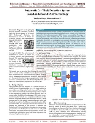
- 1. International Journal of Trend in Scientific Research and Development (IJTSRD) Volume: 3 | Issue: 4 | May-Jun 2019 Available Online: www.ijtsrd.com e-ISSN: 2456 - 6470 @ IJTSRD | Unique Paper ID - IJTSRD23867 | Volume – 3 | Issue – 4 | May-Jun 2019 Page: 689 Automatic Car Theft Detection System Based on GPS and GSM Technology Sandeep Singh1, Poonam Kumari2 1M-Tech (Instrumentation), 2Assistant Professor 1,2UCIM, Panjab University, Chandigarh, India How to cite this paper: Sandeep Singh | Poonam Kumari "Automatic Car Theft Detection System Based on GPS and GSM Technology" Published in International Journal of Trend in Scientific Research and Development (ijtsrd), ISSN: 2456- 6470, Volume-3 | Issue-4, June 2019, pp.689-692, URL: https://www.ijtsrd.c om/papers/ijtsrd23 867.pdf Copyright © 2019 by author(s) and International Journal of Trend in Scientific Research and Development Journal. This is an Open Access article distributed under the terms of the Creative Commons Attribution License (CC BY 4.0) (http://creativecommons.org/licenses/ by/4.0) ABSTRACT An efficient automotive security system is implemented for anti-theft using an embedded system integrated with Global Positioning System (GPS) and Global System for Mobile Communication (GSM. System presented has Two types of tracking, one is online tracking with GPS system can only receive the vehicle location information from satellites and other is offline tracking. GSM system is installed in the vehicle for sending the information to the owner of the vehicle. The preventive measures like engine ignition cutoff is installed in the vehicle which is controlled using user or owner GSM mobile. The owner can lock or unlock his/her vehicle with the help of SMS. The system is implemented on general purpose printed circuit board (PCB) Using Arduino. Keywords: Arduino, GPS Modem, GSM Modem, SMS, Motor 1. INTRODUCTION Vehicle tracking systems were first implemented for the shipping industry because people wanted to know where each vehicle was at any given time. These days, however, with technologygrowingatafastpace,automated vehicletracking system is being used for car theft detection which tracks and displays vehicle’s locations in real-time. GPS is a real-time satellite navigation system for three dimensional position determination. The Global System for Mobile Communications (GSM) is the second-generation digital cellularmobilenetwork. Due to its wide availability, it is chosen as the medium for transfer of location information. The simple and inexpensive Short Message Service (SMS) allows users to send up to 160 characters. System presented here incorporates the development of in-vehicle tracking device to locate the coordinates of the vehicle stolen, which are then plotted on the Google map application to get the exact and accurate location. Also the developed system can switch-off the ignition of engine with the help of SMS. 2. Design of System This project is primarily designed for car theft detection in which arduino, GSM module and GPRS are used. Arduino is used as the controlling unit of whole process. Whenever the car is stolen and forcefully started input signal (Push button in our case) will be send to the arduino. Arduino which is connected to the GSM will send an alert SMS to the owner, mentioning the latitude and longitude coordinates of the location using GPRS module. The owner will receive a short message sent by GSM module as soon as the car is stolenand forcefully started, then he/shecan requestthe locationofthe vehicle via SMS. The message will show the coordinate of latitude and longitude of the location. To address the limitations of existingvehicletracking/alarmingsystems, we presented an anti-theft system mainly based on GPS, GSM and Google map application to provide better service and cost effective solution for users. Brief detail represents the scheme of implemented system. Figure 1.1: Block diagram of scheme of the project 2.1 Literature survey Literature review reveals that many people worked for the security system of vehicle to avoid theft. Present day technologicaldevelopmentshavebeenstudied andtabulated in table below. It was found that people worked for GPRS, GSM, GPS, IOTs & web etc along with biometric sensing system. All such anti-theft modules are even available in hi- end vehicles. Here our approach is to design a cost-effective anti-theft system for low range vehicles. IJTSRD23867
- 2. International Journal of Trend in Scientific Research and Development (IJTSRD) @ www.ijtsrd.com eISSN: 2456-6470 @ IJTSRD | Unique Paper ID - IJTSRD23867 | Volume – 3 | Issue – 4 | May-Jun 2019 Page: 690 Papers followed for the implementation of the project are tabulated in the Table-2.1 Table 2.1 Papers referred for Design of project 3. Design and implementation 3.1. Hardware Framework Arduino is a physical computing platform for managingand handling electronic signals. It has an open source platform independent Integrated development environment, that facilitates programmer toprocesstheelectronicssignalfrom the attached components and control them. Arduino has prepared its own software called integrated development environment (IDE) which completely supports C and C++ programming languages. Figure 3.1: Physical look of Arduino Nano GSM Module, GSM SIM800C typeisselected to carrythetask in communication part. SIM800C is a quad-band GSM/GPRS module that works on frequencies GSM850 MHz, EGSM 900MHz, DCS1800MHz and PCS1900 MHz. Communication between Arduino and GSM module is serial. So we connect the Tx pin of GSM module to Rx pin of Arduino and Rx pin of GSM module to Tx pin of Arduino. GSM Tx –> Arduino Rx and GSM Rx –> Arduino Tx. Next connect the ground pin of arduino to ground pin of gsm module. Figure 3.2: GSM Module interfacing with arduino GPS Module The global positioning system is a satellite- based navigation system consisting of a network of 24 orbiting satellites that are eleven thousand nautical miles in space and in six different orbital paths. The satellites are constantly moving, making two complete orbits around the Earth in just under 24 hours. The orbital paths of these satellites take them between roughly 60 degrees North and 60 degrees South latitudes. Figure 3.3 GPS Module Interfacing GPS Module with arduino Arduino Pin 2 = SWseriale RX -> Connect to Ublox Neo 6M pin "TX" Arduino Pin 4 =SWseriale TX->ConnecttoUbloxNeo6M pin "RX" Arduino GND -> Connect to Ublox Neo 6M pin "GND" Arduino 5V-> Connect to Ublox Neo 6M pin "VCC" Figure 3.3: GPS Module Interfacing with Arduino 3.2. Circuit Diagram Circuit diagram shows the connection and interfacing of Arduino Nano board with GPS module, GSM module, relay and motor. Figure 3.4: circuit diagram Unauthorized ignition of engine (motor) will deliver asignal to the arduino. This arduino is coded to further activate the GSM component with pins Rx/Tx of the circuit. Which will send a warning to the owner via a text message. Simultaneously GPS will also be activated via arduino pins GND, D2, D3, 5V are connected to GND, Rx, Tx, Vcc of GSM
- 3. International Journal of Trend in Scientific Research and Development (IJTSRD) @ www.ijtsrd.com eISSN: 2456-6470 @ IJTSRD | Unique Paper ID - IJTSRD23867 | Volume – 3 | Issue – 4 | May-Jun 2019 Page: 691 respectively send back the co-ordinatesofthelocationtothe latter. This further these co-ordinates in turn are passed to the GSM which will send them to the owner. This cycle is repeated after every 10 seconds. In response to the warning owner may reply to the text message that is STOPED. Which will be received by GSM and further transmitted to arduino. Then arduino will stimulate the relay that is connectedto5V supply of arduino and will turn engine OFF. 3.3. Software development The software of the project is based on the flow chart in figure 3.4. If vehicle is forcefully ignited then automatically turn on anti theft detection system. On the other hand, If vehicle is started in authorized way feedback system automatically disables the anti-theftdetection system.When vehicle started forcefully a warning message is delivered to registered mobile number as “CarStarted”. Ownerhasaccess to stop the vehicle by sending the message “Stop” in relay and GPS enable the Arduino to send locationcoordinate.GPS attached to the arduino enable GSM to send the live coordinates of the location in every 10 second. These coordinate when used in Google map help to locatetheexact position of the vehicle Figure 3.5: Flow chart of the Project Figure 3.6: Pseudo code for the Project based on the flow chart 4. RESULT This proposed project model is tested by forcefully starting the vehicle as in case the vehicle is stolen. The results obtained are as per expectations of the project designed. As soon as the car is forcefully started by the unauthorized person, theft detection system kicks in and the owner gets the SMS within 15 to 20 seconds. There may be slight delay, if any due to mobile network. Central arduinosendssignal to control section in real time. . Figure 4.1: Working model of car theft detection system As soon the car is forcefully started by the unauthorized person which is represented by push button start on the project, Arduino initializes the GSM and GPS modules. Firstly. The alert SMS is received by theownerwhosemobile is stored in arduino programming. Figure 4.2: Message alert on mobile screen Figure 4.3: Owner responding to the alert message
- 4. International Journal of Trend in Scientific Research and Development (IJTSRD) @ www.ijtsrd.com eISSN: 2456-6470 @ IJTSRD | Unique Paper ID - IJTSRD23867 | Volume – 3 | Issue – 4 | May-Jun 2019 Page: 692 Figure 4.4: Message showing coordinates tracked by detection device After receiving the alert message from the theft detection device, the user responds via ‘STOPED’ message and after receiving the response from the owner mobile, the GPS and GSM modules keeps tracking and sending the updated location coordinates every 10 seconds to the owner mobile number. CONCLUSIONS The proposed project is a low cost, intelligent and easy to install for theft protection. This automaticcartheftdetection system will alert the user about unauthorized access and then help to locate the vehicle. The vehicle-tracking device provide the user to know his/her vehicle location in real time. The product designed is user-friendly anyone with a little knowledge of smartphone can usethis system.Itiseasy to install the system in the vehicle and it requires very low maintenance. The coordinates received shows the correct location on the Google map. Also, the size of the device is compact since the GSM and GPS modules are not present as separate module. REFERENCES [1] SeokJu Lee, Girma Tewolde and Jaerock Kwon, “Design and Implementation of Vehicle Tracking Syste Using GPS/GSM/GPRS Technology and Smartphone Application”, IEEE World Forum on Internet of Things, pp. 353-358, March 2014, Seoul. [2] H. Song, S. Zhu, and G. Cao, “Svats: A sensor-network- based vehicle anti-theft system,” IEEE INFOCOM 2008, pp.2128-2136, April.2008. [3] Shihab A. Hameed, Othman Khalifa, et,el, “Car Monitoring, Alerting andTrackingModelEnhancement with Mobility and Database Facilities,” International Conference on Computer and Communication Engineering (ICCCE 2010), pp.1-5 , May.2010. [4] M. A. A. Khedher, “Hybrid GPS-GSM localization of automobile tracking system,” International Journal of Computer Science and Information Technology, vol. 3, no. 6, pp. 75-85, Dec 2011. [5] S. S. Pethakar, N. Srivastava, and S. D. Suryawanshi, “RFID, GPS and GSM based vehicle tracing and employee security system,” International Journal of Advanced Research in Computer Science and Electronics Engineering, vol. 1, no. 10, pp. 91-96, Dec. 2012. [6] V. M. Ibrahim and A. A. Victor, “Microcontroller based anti-theft security system using GSM networks with text message as feedback,” International Journal of Engineering Research and Development, vol. 2, no. 10, pp. 18-22, Aug 2012. [7] M. A. A. Rashed, O. A. Oumar, and D. Singh, “A real time GSM/GPS based tracking system based on GSM mobile phone,” IEEE Journal on Signals and Telecommunication, vol. 3, no. 1, pp. 65-68, March 2014. [8] Pritpal Singh, Tanjot Sethi, Bibhuti Bhusan Biswal and Sujit Kumar Pattanayak, “A Smart Anti-theftSystem for Vehicle Security,” International Journal of Materials, Mechanics and Manufacturing, Vol. 3, No. 4, pp. 249- 254, November 2015. [9] Garba Suleiman, Ibrahim S. Shehu,OlumideS.Adewale, Muhammad B. Abdullahi and Solomon A. Adepoju, “Vehicle Theft Alert and Location Identification Using GSM, GPS and Web Technologies” I.J. Information Technology and Computer Science 2016, 7, 1-7. [10] Zhigang Liu, Anqi Zhang and Shaojun Li, “Vehicle anti- theft tracking system based on Internet of things” “IEEE,” pp. 48-52, 2013