
Recommended
Recommended
More Related Content
What's hot
What's hot (20)
Viewers also liked
Viewers also liked (9)
Similar to G043055064
Similar to G043055064 (20)
More from inventy
More from inventy (20)
Recently uploaded
Recently uploaded (20)
G043055064
- 1. Research Inventy: International Journal Of Engineering And Science Vol.4, Issue 3(March 2014), PP 55-64 Issn (e): 2278-4721, Issn (p):2319-6483, www.researchinventy.com 55 Lumped-parameter analytical methodology for evaluation of adaptive seat damper to enhance rotorcraft crash safety 1, Dr. Muthuvel Murugan, 2, Dr. JinHyeong Yoo, 1, 2, U.S. Army Research Laboratory – Vehicle Technology Directorate 4603 Flare Loop Drive, Aberdeen Proving Ground, MD 21005, USA. ABSTRACT: This research study focuses on the analytical evaluation of magneto-rheological (MR) dampers for enhanced occupant protection during vertical crash landings of a helicopter. The current state-of- the-art helicopter crew seat has passive safety mechanisms that are highly limited in their capability to optimally adapt to each type of crash scenario due to variations in both occupant weight and crash severity level. While passive crash energy absorbers work well for a single design condition (50th percentile male occupant and fixed crash severity level), they do not offer adequate protection across a broad spectrum of crash conditions by minimizing the load transmitted to the occupant. This study reports the development of a lumped-parameter human body model including lower leg in a seated posture for rotorcraft crash injury simulation. For implementing control, a control algorithm was made to work with the multi-body dynamic model by running co-simulation. The injury criteria and tolerance levels for the biomechanical effects are discussed for each of the identified vulnerable body regions, such as the thoracic lumbar loads for different sized adults. The desired objective of this analytical model development is to develop a tool to study the performance of adaptive semi-active magnetorheological seat suspensions for rotorcraft occupant protection. KEYWORDS: Rotorcraft crash safety, seat energy absorber, magnetorheological energy absorber, crash injury evaluation. I. INTRODUCTION Rotorcraft crew seats generally use passive energy absorbers to attenuate the vertical crash loads that are transmitted through the fuselage structure of the rotorcraft to the seated occupant (Richards et al., 1997) during a crash or hard impact landing event. These energy absorbers (EAs) include fixed-load energy absorbers (FLEAs), shown in Figure 1 or variable load energy absorbers (VLEAs) (Richards et al., 1997; Desjardins et al., 1989). These passive energy absorbing devices are not capable of automatically adapting their load-stroke profile as a function of occupant weight or as a function of varying degree of impact severity during a crash or hard landing event. In the recent times, smart adaptive energy absorbing devices, such as magneto-rheological energy absorbers (MREAs), have emerged as an innovative solution for providing active crash protection by utilizing a continuously adjustable profile EA in a controlled manner during a crash event. MREAs can adapt their stroking load as a function of occupant weight and also can respond to various impact/shock excitation levels in combination with a semi-active feedback controller. By intelligently adjusting the load-stroke profile of the MREA as the seat strokes during a hard landing or crash event, MREAs have the capability of providing an optimal combination of a short stroking distance coupled with minimal lumbar loads with varying occupant weight and impact severity level. Furthermore, MREAs offer the unique ability to use the same seat suspension system for both shock isolation during hard landings or crash impacts and for vibration isolation during normal and extreme maneuvering flight conditions. This paper presents an analytical evaluation technique to determine the performance benefits of MREA devices as compared to passive energy absorbers. This analysis method can help to fine tune the design of these adaptive systems for different crash scenarios. This model will also help in evaluating control algorithms that can be used in rotorcraft crashworthy seat systems. In this study, a lumped-parameter human body model including lower leg in seated posture was developed for crash injury assessment simulation. Typical rotorcraft crash pulse, as recommended by rotorcraft crashworthiness requirements was used to assess crash injuries in different segments of the body of the seated occupant. The injury criteria and tolerance levels for the biomechanical effects are discussed for each of the identified vulnerable body regions.
- 2. Lumped-Parameter Analytical Methodology For Evaluation Of… 56 Figure 1. Fixed-load energy absorber (FLEA) utilized in SH-60 Seahawk crew seat (Hiemenz, 2007) Nomenclature AATD Army Aviation Applied Technology Directorate DPM IM Driving-Point-Mechanical Impedance EA Energy absorber F, L Force or Load FLEA Fixed-load energy absorber IARV Injury Assessment Reference Value MREA Magneto-rheological energy absorber STH TR Seat-To-Head Transmissibility VLEA Variable load energy absorber c damping g, G gravitational acceleration k stiffness m mass ms milliseconds t Time Model Development Seated Human Model Consider a human sitting upright in a rotorcraft crew seat. A variety of mathematical models have been proposed to describe the human body‟s response to vertical disturbances. In this study, Boileau‟s model (Boileau et al., 1998) is used as a basic parameter model. However, Boileau‟s model was developed for “average” passenger comfort evaluation and it has no lower leg consideration which may be important for overall human body kinematics under extreme environment. To resolve this problem, the body segment mass was extracted from anthropometric specifications for dummy family (Herman, 2007) for the 5th percentile female (small female), 50th percentile male (average male), and 95th percentile male (large male). The proposed lumped parameter human body model, shown in Figure 2, comprises six masses for the respective six body segments, coupled by linear/nonlinear elastic and damping elements. The six masses represent the following six body segments: the head and neck (m1); the thorax (m2); the abdomen (m3); the pelvis (m4); the thighs (m5); and the calf and foot (m6). The estimated body segment mass properties are summarized in Table 1. The hand and arm masses (upper extremity) are not incorporated in the model assuming its negligible contributions to the whole-body biodynamic response. The stiffness and damping properties of the cervical spine are represented by k1 and c1, those of the thoracic spine by k2 and c2, those of the lumbar spine by k3 and c3, while those of the buttocks and thighs on a seat by k4 and c4 as shown in Figure 2. Also, there are two torsion stiffness and damping parameters for hip (k5, c5) and knee (k6, c6) joints (Ciarlet, 2004). The cited reference (Manseau et al., 2005) reported that the military boot has a significant effect on the complex lower leg injury severity. To take into account this boot effect, stiffness and damping parameters (kb and cb) were also implemented in the model as shown in Figure 2. These stiffness and damping parameters (Cikajlo et al., 2007) are summarized in Table 2 with the source of the data. Overall, this multi-body human model was developed at the U.S. Army Research Laboratory primarily for vertical impact injury assessment simulations in vehicular extreme environment scenarios such as crash or mine blast (Yoo et al., 2012).
- 3. Lumped-Parameter Analytical Methodology For Evaluation Of… 57 Figure 2. Lumped-parameter human body model Table 1. Estimated segment mass and inertial properties (Herman, 2007) Body segment Small (5th %ile) Female Medium (50th %ile) Male Large (95th %ile) Male Mass[kg] Mass[kg] Mass[kg] Head (m1) 4.30 5.10 5.68 Thorax (m2) 17.50 28.79 37.90 Abdomen (m3) 1.61 2.37 2.95 Pelvis (m4) 6.98 11.41 16.04 Thigh (m5) 11.83 17.23 21.65 Calf & foot (m6) 6.00 11.66 18.24 Total 48.22 76.56 102.46 Table 2. Stiffness and damping coefficients of the human body segments Stiffness Damping source Cervical spine (k1, c1) 310.0[kN/m] 400.0[N·s/m] (Boilea u et al., 1998) Thoracic spine (k2, c2) 183.0[kN/m] 4750.0[N·s/m] Lumbar spine (k3, c3) 162.8[kN/m] 4585.0[N·s/m] Buttocks (k4, c4) 90.0[kN/m] 2064.0[N·s/m] Hip joint (k5, c5) Extension [N·m/rad]: 68.8 Flexion [N·m/rad]: 53.2·Exp(0.98×)-53.2 100.0 [N·m·s/rad] (Ciarlet, 2004)Knee joint (k6, c6) Extension [N·m/rad]: 90.5·Exp(2.0× Flexion [N·m/rad]: 95.0·Exp(4.32×)-95.0 500.0 [N·m·s/rad] Boot (kb, cb) 300.47 [kN/m] 200.0 [N·s/m] (Cikajlo et al., 2007) The conceptual model of the rotorcraft floor structure with a crew seat used in this study is shown in Figure 3. The point „A‟ in Figure 3 shows the coupling between the seat-occupant model and the rotorcraft floor structure.
- 4. Lumped-Parameter Analytical Methodology For Evaluation Of… 58 Figure 3. Coupling between rotorcraft floor structure and seat-occupant model Biodynamic Evaluation of Seated Human Model The biodynamic responses of a seated human subjected to vertical vibration or shock exposure have widely been assessed in terms of seat-to-head (STH) transmissibility, and driving-point mechanical (DPM) impedance (Liang et al., 2006). To evaluate these performance indices, the whole human body model, shown in Figure 2, was implemented in the multi-body dynamic simulation software, MSC/ADAMS and each segment responses were simulated using the Vibration module in the software. The frequency step and frequency range of 0.5 Hz, and up to 100 Hz were selected, respectively. STH transmissibility (TR) This function, STH transmissibility (TR) is defined as the ratio of output head response to input seat excitation. It can be defined by the acceleration or displacement ratio. Therefore, TR can be expressed according to the above derivation as shown in the cited reference (Liang et al., 2006): )( )(1 A Z jZ TR (1) where is frequency, ZA() is input displacement amplitude from seat, and Z1(j) is output displacement amplitude from head and neck m1. Figure 4 presents a comparison of the transmissibility magnitude characteristics calculated from the model with the mean and envelope of the experimental data from the cited reference (Boileau et al., 1998). DPM impedance (IM) This function, DPM impedance is defined as the ratio of driving force between pelvis and seat to the input velocity of the seat. Accordingly, IM (impedance) can be represented as follows (Liang et al., 2006): )( )]()()[( 444 A A Zj jZZcjk IM (2) where is frequency, ZA() is input displacement amplitude from seat, and Z4(j) is output displacement amplitude from pelvis m4. Figure 5 presents a comparison of the impedance magnitude characteristics calculated from the model with the mean and envelope of the experimental data from the reference (Boileau et al., 1998). 1 10 100 Frequency [Hz] 0 0.4 0.8 1.2 1.6 2 SeattoHeadTR Experiment [4] Large Male Small Female
- 5. Lumped-Parameter Analytical Methodology For Evaluation Of… 59 Figure 4. Comparison of the vertical seat-to-head vibration transmissibility characteristics computed from the proposed human body model with those upper and lower limits of experimental data from (Boileau et al., 1998) 1 10 100 Frequency [Hz] 0 1000 2000 3000 4000 Impedence[Ns/m] Experiment [4] Large Male Small Female Figure 5. Comparison of the vertical driving-point mechanical impedance characteristics computed from the proposed human body model with those upper and lower limits of experimental data from (Boileau et al., 1998) Control algorithm development For vibration isolation of seat damper, high damping will suppress the amplitude response, but worsen the vibration transmissibility. Low damping will improve the transmissibility, but the relative displacement between the seat and floor may be large enough to cause end-stop impacts especially for high shock input from crash event. If the shock input force does not cause the suspension mechanism to hit the end-stop buffers, a lower suspension damping may provide greater vibration isolation performance. However, for the input force from crash event, an adjustable damper, which can be switched manually or automatically between a high damping and low damping according to the passenger‟s weight or damper deflection, might be used. If the damper is generally set to soft mode so as to provide low transmissibility, and adjust to the hard mode only when end-stop impacts are likely to occur, the optimum performance might be achieved (Wu et al., 1997). End- stop impacts will occur whenever the relative displacement between the seat and floor exceeds certain value. If the damper is switched on whenever the relative displacement exceeds a pre-set displacement threshold, dL, severe end-stop impacts might be prevented. Figure 6 shows the semi-active control algorithm flow chart for Simulink/Matlab program. This control flow implements the multi-body dynamic model block (“adams_sub” block) of MSC/ADAMS for running co-simulation with the control scheme software plug-in. The input to the “adams_sub” block is damping force, and the three outputs from the block are the seat displacement, x , Floor-pan absolute velocity, 0 x , and the seat absolute velocity, x . Considering the power limitation of Magnetorheological damper for semi-active skyhook control (Figure 6), the maximum feedback force to the “adams_sub” block was set to 15kN using the “Saturation” block function. The control scheme can be expressed as: Lseat Lseat ddxxxGG ddxxxG Fd ,)21( ,2 0 0 (3) The control gains, G1 and G2 are functions of passenger weight, and the gains for this study are summarized in Table 3 for the human body model.
- 6. Lumped-Parameter Analytical Methodology For Evaluation Of… 60 Figure 6. Simulink control flow diagram for end-stop control Table 3. Control parameters Body model Small (5th %ile) Female Medium (50th %ile) Male Large (95th %ile) Male Unit G1 1 2 3 kN/(m/s) G2 0.01 0.05 0.3 kN/(m/s) dL 335 335 335 mm Rotorcraft crash pulse Based on a study of survivable crash scenarios for U.S. Army helicopters during 1950‟s and 1960‟s, design guidelines and detailed requirements were developed for military crew seats as defined in MIL-S- 85510(AS) (Military Specification – MIL-S-85510(AS), 1981) and for civil rotorcraft seats in SAE, AS8049 (Aerospace Standard – SAE AS8049A, 1997). Recently Full Spectrum Crashworthiness Criteria for rotorcraft have been published by U.S. Army RDECOM (Army Aviation Applied Technology Directorate (AATD)) (US Army RDECOM report RDECOM TR-12-D-12, 2011). Based on these published guidelines, crash pulse for vertical impacts of military helicopters with a Vz = 42ft/sec (Desjardins et al., 1989; US Army REDCOM report RDECOM TR-12-D-12, 2011) was used for this research. A typical rotorcraft vertical impact crash pulse profile as shown schematically in Figure 7 was utilized with seat-occupant model for the analytical evaluation of passive EA and semi-active MREA. The maximum deceleration and the deceleration-time history relationship (pulse) developed for the design of a crashworthy seat system for a military helicopter is given below in Figure 7. In Figure 7, Gm refers to maximum deceleration; tm is the time to reach maximum deceleration Gm; and GL is the limit-load deceleration. The deceleration of the occupant must be limited to a level, GL such that the applied loads are of a humanly tolerable time-magnitude relationship. Once the seat- occupant system reaches this limit load deceleration (GL), the seat strokes at constant load factor keeping the occupant‟s lumbar load within tolerable limits. After extensive analysis of crash injury data, it was determined that the limit-load deceleration level should be 14.5g (Military Specification – MIL-S-85510(AS), 1981). So, the crash energy absorbing systems (EAs) for military helicopter seats should be sized for a limit load that is 14.5 times the effective weight of the seat-occupant system including restraints and other body-worn items. This limit load factor was later verified by cadaveric testing and analysis as well (Aerospace Standard – SAE AS8049A, 1997). The limit load, L L varies with the occupant-seat (O-S) system effective weight and it can be calculated as follows: )(5.14 )( lbWgL effSOL (4) Where )()( lbW effSO is the effective occupant-seat system weight. For varying occupant sizes (5th %ile through 95th %ile occupants), this varying limit load can be calculated, and EA systems can be designed and controlled to the required stroking load keeping the stroke within allowable design limits.
- 7. Lumped-Parameter Analytical Methodology For Evaluation Of… 61 Gm = 48g 2tm = 54msec Vz = 42ft/sec GL = 14.5g Figure 7. Typical rotorcraft pulse profile and deceleration limit for the seated occupant (Hiemenz, 2007) The complete model set-up for simulations are conceptually shown in Figure 8 for the passive EA (Baseline - no control) and semi-active EA, MREA (with control). The control algorithm was implemented using co-simulation with seat-occupant dynamic model. (a) Passive EA (Baseline) (b) Semi-active EA (MREA with Control Figure 8. Schematic sketch of simulations for Passive EA and MREA (Hiemenz, 2007) Injury assessment criteria The key injury assessment parameter such as the lumbar loads would be the primary focus in comparing the performance benefits of passive EA and MREA. The lumbar load injury assessment reference values (IARVs) as stipulated in the Full Spectrum Crashworthiness Criteria published by the U.S. Army Aviation Applied Technology Directorate (AATD) (U.S. Army RDEOM report RDECOM TR-12-D-12, 2011) were used as reference (Table 4) for evaluation of MREA through analysis. The IARVs for lumbar load injury criteria for tolerable limits were used for comparison of performance between the passive EA (Baseline) and MREA with Control cases. Table 4. Injury Assessment Criteria Injury Assessment Parameter IARV Lumbar load < 933 lb for 5th %ile < 1395 lb for 50th %ile < 1757 lb for 95th %ile (per Full Spectrum Crashworthiness Criteria guidelines (US Army RDECOM report RDECOM TR-12-D-12, 2011))
- 8. Lumped-Parameter Analytical Methodology For Evaluation Of… 62 Simulation results and discussion The biodynamic model, shown in Figure 2 and rotorcraft floor model, shown in Figure 3 were combined and implemented in MSC/ADAMS as shown in Figure 9. An active control element was implemented and designed to generate force in between floor-pan and seat. The non-linear human biodynamic model was co-simulated with Simulink control scheme plug-in, as shown in Figure 6. “Co-Simulation” (co- operative simulation) is a simulation methodology that allows individual components to be simulated using different simulation tools running simultaneously and exchanging information in a collaborative manner. The nonlinear human body model in MSC/ADAMS was generated in Simulink accessible code (.m-file and .mdl- file, “adams_sub” block in Figure 6) through ADAMS/Control module. Figure 9. A lumped-parameter seat-occupant model The figures 10 through 12 show the simulation results for three cases, namely, 5th %ile, 50th %ile, and 95th %ile occupant models. Figure 10 show the reduction of lumbar load for 5th %ile analysis case between the baseline (passive EA with no control) and MREA with control. In Figure 10, the peak lumbar load for the Baseline case is 1477 lbf (exceeds IARV limit), whereas the peak load for MREA with Control analysis case is 926 lbf (< 933 lbf (IARV)). Thus, it has been shown through analysis that by choosing an adaptive MREA with right type of control algorithm, it is possible to mitigate thoracic spinal injury (lumbar load is a measure of this injury) to a seated occupant in a rotorcraft vertical crash event. In Figure 11 for the 50th %ile analysis case, the peak lumbar load is reduced from 2248 lbf (Baseline) to 1388 lbf (MREA with Control) keeping the lumbar load well within the IARV limit for this severe crash scenario. Also, in Figure 12 for the 95th %ile occupant analysis case, it has been shown that the peak lumbar load can be reduced from 2342 lbf to 1748 lbf, which is well within the IARV limit. These analysis cases show that it is possible to optimize the adaptive MREA device with a proper control algorithm for the crash scenarios that are of interest to improve the safety and survivability in rotorcraft crashes. Figure 10. Baseline vs. MREA with control – for 5th %ile occupant Peak Lumbar Load (Baseline) = 1477 lb Peak Lumbar Load (MREA w/Control) = 926 lb Lumbar Load - IARV Limit for 5th %ile = 933lb
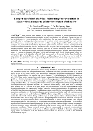
- 9. Lumped-Parameter Analytical Methodology For Evaluation Of… 63 Figure 11. Baseline vs. MREA with control – for 50th %ile occupant Figure 12. Baseline vs. MREA with control – for 95th %ile occupant Peak Lumbar Load (Baseline) = 2248 lb Peak Lumbar Load (MREA w/Control) = 1388 lb Lumbar Load - IARV Limit for 50th %ile = 1395 lb) Peak Lumbar Load (Baseline) = 2342 lb Peak Lumbar Load (MREA w/Control) = 1748 lb Lumbar Load - IARV Limit for 95th %ile = 1757 lb)
- 10. Lumped-Parameter Analytical Methodology For Evaluation Of… 64 Summary and conclusions This analytical research study proposes a lumped-parameter human body model including lower leg in seated posture for rotorcraft crashworthiness simulation and crash safety seat development with an adaptive semi-active seat energy absorber. The multi-body, lumped parameters were developed to represent a seated occupant in a rotorcraft interior environment. The upper extremity was neglected in the analysis model, since it is assumed that it has negligible effects on the overall bio-dynamics of the human body during a crash event. The developed models are applicable for an “average” human subject (close to a 50th percentile male), a small female 5th %ile human subject, and a large male 95th %ile human subject. The developed rotorcraft vehicle occupant model, with the chosen parameters, provides a reasonable estimate of the seat-to-head transmissibility (TR), and driving-point impedance (IM) characteristics defined as applicable to target experimental values for ensuring bio-fidelity of the model. A generic rotorcraft vertical crash pulse as stipulated in military design standards was used to evaluate the performance of MREA seat energy absorber with a suitable control algorithm. The goal of this research was to establish a high fidelity lumped parameter seat-occupant model and a simulation methodology with a suitable control algorithm that can be used to evaluate and design adaptive magnetorheological energy absorbers for rotorcraft crashworthy safety seat application. The established model will also be helpful in the evaluation different types of control schemes for the efficient use of the adaptive MREAs to meet crew safety requirements with varying occupant sizes and vertical impact sink rates. An analysis methodology to co-simulate control algorithms together with lumped-parameter, multi-body seat- occupant system model with adaptive MREA device was demonstrated as well. It has been shown through this study that lumbar load reduction and consequent spinal injury mitigation can be achieved for all sizes of adults in a rotorcraft vertical crash event by using an adaptive semi-active seat energy absorber, such as a magnetorheological energy absorber with a suitable control algorithm to control the energy absorber actuation during the crash event. A seat-occupant system level test set-up with an “iron-bird” seat (structurally strengthened seat structure for repeated sled tests) is being built for energy absorber technology demonstration as part of this research project. Dynamic sled testing with full scale crash loads will be conducted for demonstration and verification of different types of seat damper technologies in future. Acknowledgment The authors would like to acknowledge the research funding awarded by the Joint Aircraft Survivability Program Office, USA for this research work. REFERENCES [1]. Aerospace Standard – SAE, AS8049A (1997), Performance Standard For Seats in Civil Rotorcraft, Transport Aircraft, and General Aviation, Issued July 1990 and Revised September 1997. [2]. Boileau PÉ., Rakheja S (1998) Whole-body vertical biodynamic response characteristics of the seated vehicle driver, Measurement and model development, International Journal of Industrial Ergonomics, 22, pp. 449-472. [3]. Ciarlet PG (2004) Handbook of Numerical Analysis, Volume XII Special Volume: Computational Models for the Human Body, Guest Editor: N. Ayache, Elsevier, North Holland, pp. 392. [4]. Cikajlo I and Matjačić Z (2007) The influence of boot stiffness on gait kinematics and kinetics during stance phase, Ergonomics, 50(12), pp.2171-2182. [5]. Desjardins SP, Zimmerman RE, Bolukbasi AO, and Merritt NA (1989) Aircraft Crash Survival Design Guide Vol. IV – Aircraft Seats, Restraints, Litters, and Cockpit/Cabin Delethalization, Aviation Applied Technology Directorate, USAAVSCOM Technical Report 89-D-22D, 1989, pp. 45-58, 83-109, & 165. [6]. Herman IP (2007) Physics of the Human Body, Springer-Verlag Berlin Heidelberg, NY, pp. 16-17. [7]. Hiemenz GJ (2007) Semi-Active Magnetorheological Seat Suspensions for Enhanced Crashworthiness and Vibration Isolation of Rotorcraft Seats, Ph.D. dissertation, University of Maryland, College Park, MD, USA. [8]. Liang C-C and Chiang C-F (2006) A study on biodynamic models of seated human subjects exposed to vertical vibration, International Journal of Industrial Ergonomics, 36, pp. 869-890. [9]. Manseau J and Keown M (2005) Development of an assessment methodology for lower leg injuries resulting from antivehicular blast landmines, IUTAM Proceedings on Impact Biomechanics: From Fundamental Insights to Applications, Springer, The Netherlands, pp. 33-40. [10]. Military Specification – MIL-S-85510(AS) (1981) Military Specification, Seats, Helicopter Cabin, Crashworthy, General Specification For, Department of Defense, Washington, DC 20301, 19 November 1981. [11]. Richards M and Podob R (1997) Development of an Advanced Energy Absorber, Proceedings of 35th annual SAFE symposium, 1997. [12]. U.S. Army RDECOM report (2011) Full Spectrum Crashworthiness Criteria for Rotorcraft, RDECOM TR 12-D-12, Aviation Applied Technology Directorate, December 2011. [13]. Wu X and Griffin MJ (1997) A Semi-Active Control Policy to Reduce the Occurrence and Severity of End-Stop Impacts in a Suspension Seat with an Electrorheological Fluid Damper, Journal of Sound and Vibration, 203(5), 26 June 1997, pp. 781-793. [14]. Yoo JH, Murugan M, and Le DD (2012) Development of a lumped-parameter occupant injury assessment model for vehicular blast effects simulation, Proceedings of the ASME 2012 Conference on Smart Materials, Adaptive Structures and Intelligent Systems, Sept. 19-21, 2012, Stone Mountain, GA.