SlideShare una empresa de Scribd logo
1 de 23
Chapter 5: Sheet metal forming processes

   •   The term press working or press forming is used commonly in industry to
       describe general sheet-forming operations, because they typically are performed
       on presses using a set of dies.
   •   Low-carbon steel is the most commonly used sheet metal because of its low cost
       and generally good strength and formability characteristics.
   •   Table 16.1 shows the general characteristics of sheet-metal forming processes.


Shearing
   • Before a sheet-metal part is made, a blank of suitable dimensions first is removed
       from a large sheet (usually from a coil) by shearing.


                                           1
•   Fig 16.2 (a) shows schematic illustration of shearing with a punch and die,
       indicating some of the process variables. Characteristic features of (b) a punched
       hole; (c) the slug.
   • The rough fracture surfaces are due to these cracks; the smooth and shiny
       burnished surfaces on the hole and the slug are from the contact and rubbing of
       the sheared edge against the walls of the punch and die, respectively.
   • The major processing parameters in shearing are
   1. The shape of the punch and die
   2. The speed of punching
   3. Lubrication
   4. The clearance, c, between the punch and the die
   As the clearance increases, the material tends to be pulled into the die rather than be
   sheared. In practice, clearances usually range between 2 and 10% of the thickness of
   the sheet.


Punch force
   • The force required to punch is basically the product of the shear strength of the


                                            2
sheet metal and the total area being sheared along the periphery.
   •   The maximum punch force, F, can be estimated from the equation

         F = 0.7TL( UTS )     (16.1)

       where T is the sheet thickness, L is the total length sheared (such as the perimeter
       of a hole), and UTS is the ultimate tensile strength of the material.

   •   Friction between the punch and the work piece can, however, increase punch
       force significantly.
   •   Furthermore, in addition to the punch force, a force is required to strip the punch
       from the sheet during its return stroke.

Example 16.1 Calculation of punch force
Estimate the force required for punching a 25-mm diameter hole through a 3.2-mm thick
annealed titanium-alloy Ti-6Al-4V sheet at room temperature.

Solution The force is estimated from Eq. (16.1) where the UTS for this alloy is found
from Table 6.10 to be 1000 MPa. Thus,
    F = 0.7( 3.2 )(π )( 25)(1000 ) = 0.18 MN


Shearing Operations
   • The most common shearing operations are punching—where the sheared slug is
       scrap or may be used for some other purpose—and blanking—where the slug is
       the part to be used and the rest is scrap.
   • Fig 16.4 (a) shows punching (piercing) and blanking, while (b) shows the
       examples of various die-cutting operations on sheet metal.
   • This is a shearing operation that consists of the following basic processes:
   1. Perforating: punching a number of holes in a sheet
   2. Parting: shearing the sheet into two or more pieces
   3. Notching: removing pieces (or various shapes) from the edges
   4. Lancing: leaving a tab without removing any material


Fine blanking
   • Very smooth and square edges can be produced by fine blanking.


                                               3
•   Fig 16.5(a) shows the comparison of sheared edges produced by conventional
       (left) and by fine-blanking (right) techniques and (b) shows schematic illustration
       of one setup for fine blanking.


Slitting
    • In slitting, the blades follow either a straight line, a circular path, or a curved path.
    • Fig 16.6 shows the slitting with rotary knives.
    • This process is similar to opening cans.


Steel rules
    • Soft metals (as well as paper, leather, and rubber) can be blanked with a steel-rule
        die.


                                              4
•   The die is pressed against the sheet which rests on the flat surface, and it shears
       the sheet along the shape of the steel rule.
   •   Soft metals (as well as paper, leather, and rubber) can be blanked with a steel-rule
       die.
   •   The die is pressed against the sheet which rests on the flat surface, and it shears
       the sheet along the shape of the steel rule.

Characteristics and type of shearing dies
Clearance
   • Because the formability of the sheared part can be influenced by the quality of its
       sheared edges, clearance control is important.
   • The appropriate clearance depends on
   1. The type of material and its temper
   2. The thickness and size of the blank
   3. Its proximity to the edges of other sheared edges or the edges of the original blank

   As a general guideline, (a) clearances for soft materials are less than those for harder
   grades; (b) the thicker the sheet, the larger the clearance must be; and (c) as the ratio
   of hole diameter to sheet thickness decreases, clearances should be larger.

Punch and Die
   • Both the surfaces of the punch and of the die are flat.
   • Because the entire thickness is sheared at the same time, the punch force increases
       rapidly during shearing.
   • The location of the regions being sheared at any particular instant can be
       controlled by beveling the punch and die surfaces.
   • Fig 16.10 shows the examples of the use of shear angles on punches and dies.


Compound dies
  • Several operations on the same sheet may be performed in one stroke at one
     station with a compound die.
  • Such combined operations usually are limited to relatively simple shapes, because
     (a) the process is somewhat slow and (b) the dies rapidly become much more
     expensive to produce than those for individual shearing operations, especially for
     complex dies.


                                             5
6
Progressive dies
   • Parts requiring multiple operations to produce can be made at high production
       rates in progressive dies.
   • The sheet metal is fed through as a coil strip, and a different operation (such as
       punching, blanking, and notching) is performed at the same station of the machine
       with each stroke of a series of punches.
Transfer dies
   • In a transfer-die setup, the sheet metal undergoes different operations at different
       stations of the machine which are arranged along a straight line or a circular path.
   • After each step in a station, the part is transferred to the next station for further
       operations.
Tool and die materials
   • Tool and die materials for shearing generally are tool steels and (for high
       production rates) carbides.


                                            7
•   Lubrication is important for reducing tool and die wear, thus improving edge
       quality.

Miscellaneous methods of cutting sheet metal
   • There are several other methods of cutting sheets and, particularly, plates:
   1. Laser-beam cutting is an important process typically used with computer-
       controlled equipment to cut a variety of shapes consistently, in various
       thicknesses, and without the use of any dies.
   2. Water-jet cutting is a cutting process that is effective on many metallic as well as
       nonmetallic materials.
   3. Cutting with a band saw; this method is a chip-removal process.
   4. Friction sawing involves a disk or blade which rubs against the sheet or plate at
       high surface speeds.
   5. Flame cutting is another common method, particularly for thick plates; it is used
       widely in ship building and on heavy structural components.


Bending sheets and plates
   • Bending is one of the most common industrial forming operations.
   • Fig 16.16 shows the bending terminology. Note that the bend radius is measured
      to the inner surface of the bent part.
   • Fig 16.17 (a) and (b) shows the effect of elongated inclusions (stringers) on
      cracking as a function of the direction of bending with respect to the original
      rolling direction of the sheet. (c) Cracks on the outer surface of an aluminum strip
      bent to an angle of 90°.


                                             8
•   The bend allowance, is the length of the neutral axis in the bend and is used to
       determine the length of the blank for a part to be bent.
   •   An approximate formula for the bend allowance is given by
                 Lb = α ( R + kT )       ( 16.2)
       where α is the bend angle (in radians), T is the sheet thickness, R is the bend
       radius, and k is a constant.

Minimum bend radius
   • The radius at which a crack first appears at the outer fibers of a sheet being bent is
      referred to as the minimum bend radius.
   • It can be shown that the engineering strain on the outer and inner fibers of a sheet
      during bending is given by the expression
                              1
                   e=                      ( 16.4)
                        ( 2R / T ) + 1
   •   Thus, as R/T decreases (that is, as the ratio of the bend radius to the thickness
       becomes smaller), the tensile strain at the outer fiber increases, and the material
       eventually develops cracks.
   •   Table 16.3 shows the minimum bend radius for various materials at room
       temperature.
   •   Fig 16.18 shows the relationship between R/T ratio and tensile reduction of area
       for sheet metals. Note that sheet metal with a 50% tensile reduction of area can be


                                                     9
bent over itself in a process like the folding of a piece of paper without cracking.
   •   The minimum bend radius, R, is, approximately,
                             50 
                      R = T  − 1     (16.5)
                             r 
       where r is the tensile reduction of area of the sheet metal.


   •   Another significant factor in edge cracking is the amount, shape, and hardness of
       inclusions present in the sheet metal and the amount of cold working that the
       edges undergo during shearing.
   •   Anisotropy of the sheet is another important factor in bendability.
   •   Cold rolling results in anisotropy by preferred orientation or by mechanical
       fibering due to the alignment of any impurities, inclusions, and voids that may be
       present.


Springback
   • Because all materials have a finite modulus of elasticity, plastic deformation
       always is followed by some elastic recovery when the load is removed.
   • In bending, this recovery is called springback, which can be observed easily by
       bending and then releasing a piece of sheet metal or wire.
   • Fig 16.9 shows the springback in bending. The part tends to recover elastically
       after bending, and its bend radius becomes larger. Under certain conditions, it is
       possible for the final bend angle to be smaller than the original angle (negative
       springback).


Reduce or eliminate
springback
                                                                          •   Fig 16.20
                                                                              shows the
                                                                              methods of


                                                10
reducing or eliminating springback in bending operations.
   •   Springback in forming operations usually is compensated for by overbending the
       part.
   •   Coin the bend area by subjecting highly localized compressive stress between
       punch tip and die surface – bottoming
   •   Stretch bending


Bending force
   • The bending force for sheets and plates can be estimated by assuming that the
      process is one of the simple bending of a rectangular beam.
   • Excluding friction, the maximum bending force, P, is
                                  kYLT 2
                             P=                      ( 16.7)
                                    W
   where the factor k ranges from about 0.3 for a wiping die, to about 0.7 for a U-die.
   • For a V-die, Eq. (16.7) is often modified as

         P=
              ( UTS ) LT 2                 ( 16.8)
                  W
   where UTS is the ultimate tensile strength of the material.
Various bending operations
Press-brake forming
   • Sheets or narrow strips that are 7 m or even longer usually are bent in a press
       brake.
   • Fig 16.23(a) through (e) shows the schematic illustrations of various bending
       operations in a press brake, and (f) shows the schematic illustration of a press


                                                               11
brake.
   •   The process can be automated easily for low-cost, high-production runs.
   •   Die materials for press brakes may range from hardwood (for low-strength
       materials and small-production runs) to carbides for strong and abrasive sheet
       materials and also are chosen to improve die life.


Roll bending
   • In this process, plates are bent using a set of rolls.
   • By adjusting the distance between the three rolls, various curvatures can be
       obtained.
   • This process is flexible and is used widely for bending plates for applications such
       as boilers, cylindrical pressure vessels, and various curved structural members.


                                           12
Beading
   • In beading, the periphery of the sheet metal is bent into the cavity of a die.
   • The bead imparts stiffness to the part by increasing the moment of inertia of that
      section.
   • Also, beads improve the appearance of the part and eliminate exposed sharp edges
      that can be hazardous.
   • Fig 16.24(a) shows bead forming with a single die. (b) though (d) Bead forming
      with two dies in a press brake.


Flanging
   • This is a process of bending the edges of sheet metals, usually to 90°.
   • In shrink flanging, the flange is subjected to compressive hoop stresses which, if
       excessive, can cause the flange periphery to wrinkle.
   • The wrinkling tendency increases with decreasing radius of curvature of the
       flange.
   • In stretch flanging, the flange periphery is subjected to tensile stresses that, if
       excessive, can lead to cracking along the periphery.


                                           13
Deep Drawing
   • Numerous parts made of sheet metal are cylindrical or box shaped, such as pots
      and pans, all types of containers for food and beverages, stainless-steel kitchen
      sinks, canisters, and automotive fuel tanks.
   • Fig 16.31 shows the metal-forming processes involved in manufacturing a two-
      piece aluminum beverage can.
   • The process generally is called deep drawing because of its capability for
      producing deep parts)
   • It also is used to make parts that are shallow or have moderate depth and is one of
      the most important metalworking processes because of the wide use of products
      made.
   • Fig 16.32(a) shows the schematic illustration of the deep-drawing process on a
      circular sheet-metal blank.
   • The stripper ring facilitates the removal of the formed cup from the punch.
   • Fig 16.32(b) shows the process variables in deep drawing.
   • Except for the punch force, F, all the parameters indicated in the figure are
      independent variables.
   • The maximum punch force, Fmax can be estimated from the formula


                                           14
[
Fmax = πD pT (UTS ) ( Do / D p ) − 0.7   ]   (16.9)


                                     15
Deep drawability
   • In a deep-drawing operation, failure generally results from the thinning of the cup
      wall under high longitudinal tensile stresses.
   • Deep drawability generally is expressed by the limiting drawing ratio (LDR), as

                Maximum blank diameter Do
        LDR =                         =           (16.10)
                    Punch diameter      Dp

   •   Whether a sheet metal can be deep drawn successfully into a round cup-shaped
       part has been found to be a function of the normal anisotropy, R, of the sheet
       metal (also called plastic anisotropy).
   •   Normal anisotropy is defined in terms of the true strains that the specimen
       undergoes in tension:
             Width strain   ε
        R=                 = w         (16.11)
           Thickness strain ε t
   •   An average value, Ravg, is calculated from the equation
                 R + 2R + R
           Ravg = 0 45 90            ( 16.12)
                      4
   •   Some typical values of Ravg are given in Table 16.4.


                                             16
Earing
                                                                           •  In drawing,
                                                                              the edges of
                                                                              cups may
                                                                              become
                                                                              wavy—a
                                                                              phenomenon
                                                                              called
                                                                              earing.
                                                                          • Fig 16.35
         shows the earing in a drawn steel cup caused by the planar anisotropy of the sheet
         metal.


Deep-drawing practice
                                                                   •    Draw beads often
                                                                        are necessary to
                                                                        control the flow of
                                                                        the blank into the
                                                                        die cavity.
                                                                      • Fig 16.36(a) shows
                                                                        schematic
                                                                        illustration of a
         draw bead. (b) Metal flow during the drawing of a box-shaped part while using
         beads to control the movement of the material. (c) Deformation of circular grids
         in the flange in deep drawing.
   •     Draw beads also are useful in drawing box-shaped and nonsymmetric parts,
         because they can present significant difficulties in practice.


   •  In order to avoid tearing of the sheet metal during forming, it often is necessary to
      incorporate the following factors:
   1. Proper design and location of draw beads


                                             17
2.   Large die radii
   3.   Effective lubrication
   4.   Proper blank size and shape
   5.   The cutting off of corners of square or rectangular blanks at 45° to reduce tensile
        stresses developed during drawing
    6. The use of blanks free of internal and external defects
Ironing
    • Note in Fig. 16.32 that if the clearance between the punch and the die is
        sufficiently large, the drawn cup will have thicker walls at its rim than at its base.
    • The reason for this is that the cup rim consists of material from the outer diameter
        of the blank, hence it has been reduced in diameter more (and thus becomes
        thicker) than the material constituting the rest of the cup wall.
Redrawing
    • Containers that are too difficult to draw in one operation generally undergo
        redrawing.
    • Because of the volume constancy of the metal, the cup becomes longer as it is
        redrawn to smaller diameters.
    • In reverse redrawing, the cup is placed upside down in the die and thus is
        subjected to bending in the direction opposite to its original configuration.
Drawing without blankholder
    • Deep drawing also may be carried out successfully without a blankholder,
        provided that the sheet metal is sufficiently thick to prevent wrinkling.
    • A typical range of the diameter is
                                     Do − D p < 5T    (16.14)
       where T is the sheet thickness.
Tooling and equipment for drawing
   • The most common tool and die materials for deep drawing are tool steels and cast
       irons and include dies produced from ductile iron castings made by the lost-foam
       process.
   • The equipment for deep drawing is usually a double-action hydraulic press or a
       mechanical press, the latter generally being favored because of its higher
       operating speed.

Rubber Forming
   • Polyurethanes are used widely because of their
   1. Resistance to abrasion
   2. Resistance to cutting or tearing by burrs or other sharp edges on the sheet metal
   3. Long fatigue life
   • In the bending and embossing of sheet metal by this process, the female die is
      replaced with a rubber pad.
   • Fig 16.39 shows the examples of the bending and the embossing of sheet metal
      with a metal punch and with a flexible pad serving as the female die.


                                                18
•   In the hydroform or fluid-forming process, the pressure over the rubber membrane
       is controlled throughout the forming cycle with a maximum pressure of up to 100
       MPa.
   •   Fig 16.40 shows the the hydroform (or fluid-forming) process. Note that in
       contrast to the ordinary deep drawing process, the pressure in the dome forces the
       cup walls against the punch. The cup travels with the punch; in this way, deep
       drawability is improved.


When selected properly, rubber-forming and hydroforming processes have the
advantages of (a) the capability to form complex shapes,
 (b) forming parts with laminated sheets of various materials and coatings,
 (c) flexibility and ease of operation,
 (d) the avoidance of damage to the surfaces of the sheet,
 (e) low die wear, and
 (f) low tooling cost.


                                           19
Spinning
   • Spinning is a process which involves the forming of axisymmetric parts over a
       mandrel by the use of various tools and rollers—a process that is similar to that of
       forming clay on a potter’s wheel.

Conventional spinning
   • In conventional spinning, a circular blank of flat or preformed sheet metal is
      placed and held against a mandrel and rotated while a rigid tool deforms and
      shapes the material over the mandrel.
   • Fig 16.42(a) shows the schematic illustration of the conventional spinning
      process. (b) Types of parts conventionally spun. All parts are axisymmetric
   • Although most spinning is performed at room temperature, thick parts and metals
      with high strength or low ductility require spinning at elevated temperatures


Shear spinning
   • The spinnability of a metal in this process generally is defined as the maximum
       reduction in thickness to which a part can be subjected by spinning without
       fracture.
   • For metals with low ductility, the operation is carried out at elevated temperatures
       by heating the blank in a furnace and transferring it rapidly to the mandrel.


                                            20
Tube spinning
   • In tube spinning, the thickness of hollow, cylindrical blanks is reduced or shaped
       by spinning them on a solid, round mandrel using rollers.
   • The reduction in wall thickness results in a longer tube.
   • Tube spinning can be used to make rocket, missile, and jet engine parts, pressure
       vessels, and automotive components, such as car and truck wheels.


                                           21

Más contenido relacionado

La actualidad más candente

Dies Design - Cutting Operations Part 2
Dies Design - Cutting Operations Part 2Dies Design - Cutting Operations Part 2
Dies Design - Cutting Operations Part 2Federick Pocoyo
 
STUDY OF HYDRO FORMING PROCESS
STUDY OF HYDRO FORMING PROCESSSTUDY OF HYDRO FORMING PROCESS
STUDY OF HYDRO FORMING PROCESSChetan Patil
 
01 fundamentals of metalworking
01 fundamentals of metalworking01 fundamentals of metalworking
01 fundamentals of metalworkingajit_singh206
 
Sheet metal-forming-processes
Sheet metal-forming-processesSheet metal-forming-processes
Sheet metal-forming-processessahilslideshare
 
Sheet metal forming process Chapter 7
Sheet metal forming process Chapter 7Sheet metal forming process Chapter 7
Sheet metal forming process Chapter 7Hosam Hane
 
Extrusion process
Extrusion processExtrusion process
Extrusion processAli Hameed
 
Sheet metal process unit 4 notes
Sheet metal process unit 4 notesSheet metal process unit 4 notes
Sheet metal process unit 4 notesrmkcet
 
Overview of extrusion process
Overview of extrusion processOverview of extrusion process
Overview of extrusion processVamsi Krishna
 
Sheet Metal Micro Forming: Future Research Potentials
Sheet Metal Micro Forming: Future Research PotentialsSheet Metal Micro Forming: Future Research Potentials
Sheet Metal Micro Forming: Future Research PotentialsIDES Editor
 
Shearing introduction
Shearing introduction  Shearing introduction
Shearing introduction Mohamed Yaser
 
Bulk deformation Processes in Metal Working
Bulk deformation Processes in Metal WorkingBulk deformation Processes in Metal Working
Bulk deformation Processes in Metal WorkingMuhammadUsman1795
 
Me2026 ump
Me2026 umpMe2026 ump
Me2026 umpAinnar K
 

La actualidad más candente (20)

Dies Design - Cutting Operations Part 2
Dies Design - Cutting Operations Part 2Dies Design - Cutting Operations Part 2
Dies Design - Cutting Operations Part 2
 
STUDY OF HYDRO FORMING PROCESS
STUDY OF HYDRO FORMING PROCESSSTUDY OF HYDRO FORMING PROCESS
STUDY OF HYDRO FORMING PROCESS
 
Shearing
ShearingShearing
Shearing
 
01 fundamentals of metalworking
01 fundamentals of metalworking01 fundamentals of metalworking
01 fundamentals of metalworking
 
Sheet metal-forming-processes
Sheet metal-forming-processesSheet metal-forming-processes
Sheet metal-forming-processes
 
Mechanics of chips formation
Mechanics of chips formationMechanics of chips formation
Mechanics of chips formation
 
Sheet metal forming process Chapter 7
Sheet metal forming process Chapter 7Sheet metal forming process Chapter 7
Sheet metal forming process Chapter 7
 
Extrusion process
Extrusion processExtrusion process
Extrusion process
 
Stamping dies
Stamping diesStamping dies
Stamping dies
 
Sheet metal process unit 4 notes
Sheet metal process unit 4 notesSheet metal process unit 4 notes
Sheet metal process unit 4 notes
 
Overview of extrusion process
Overview of extrusion processOverview of extrusion process
Overview of extrusion process
 
Electron beam machining
Electron beam machiningElectron beam machining
Electron beam machining
 
Sheet Metal Micro Forming: Future Research Potentials
Sheet Metal Micro Forming: Future Research PotentialsSheet Metal Micro Forming: Future Research Potentials
Sheet Metal Micro Forming: Future Research Potentials
 
Shearing introduction
Shearing introduction  Shearing introduction
Shearing introduction
 
Dr.R.Narayanasamy - Metal forming part - I.
Dr.R.Narayanasamy - Metal forming part - I.Dr.R.Narayanasamy - Metal forming part - I.
Dr.R.Narayanasamy - Metal forming part - I.
 
Bulk deformation Processes in Metal Working
Bulk deformation Processes in Metal WorkingBulk deformation Processes in Metal Working
Bulk deformation Processes in Metal Working
 
forging
forgingforging
forging
 
Single point cutting tool
Single point cutting toolSingle point cutting tool
Single point cutting tool
 
Me2026 ump
Me2026 umpMe2026 ump
Me2026 ump
 
Metal forming defects
Metal forming defectsMetal forming defects
Metal forming defects
 

Destacado

Sheet Metal Forming
Sheet Metal FormingSheet Metal Forming
Sheet Metal Formingvins049
 
Sheet metal processes
Sheet metal processesSheet metal processes
Sheet metal processesJagadeesh Km
 
Sheet metal forming processes Erdi Karaçal Mechanical Engineer University of ...
Sheet metal forming processes Erdi Karaçal Mechanical Engineer University of ...Sheet metal forming processes Erdi Karaçal Mechanical Engineer University of ...
Sheet metal forming processes Erdi Karaçal Mechanical Engineer University of ...Erdi Karaçal
 
Sheet metal-operations
Sheet metal-operationsSheet metal-operations
Sheet metal-operationsPrasanna M N
 
Sheet metworking 1
Sheet metworking 1Sheet metworking 1
Sheet metworking 1sundar sivam
 
Mm9501 milling tutorial
Mm9501 milling tutorialMm9501 milling tutorial
Mm9501 milling tutorialwongchukhang
 
Sistema informatic
Sistema informaticSistema informatic
Sistema informaticEdu Alias
 
Facility Planning for Fire extinguisher
Facility Planning for Fire extinguisherFacility Planning for Fire extinguisher
Facility Planning for Fire extinguisherMahmoud Farg
 
TALAT Lecture 2711: Design of a Helicopter Deck
TALAT Lecture 2711: Design of a Helicopter DeckTALAT Lecture 2711: Design of a Helicopter Deck
TALAT Lecture 2711: Design of a Helicopter DeckCORE-Materials
 
SHEET METAL PART QUALITY IMPROVEMENT THROUGH DIE OPTIMIZATION USING AUTOFORM
SHEET METAL PART QUALITY IMPROVEMENT THROUGH DIE OPTIMIZATION USING AUTOFORMSHEET METAL PART QUALITY IMPROVEMENT THROUGH DIE OPTIMIZATION USING AUTOFORM
SHEET METAL PART QUALITY IMPROVEMENT THROUGH DIE OPTIMIZATION USING AUTOFORMFarhad ZHalehfar
 
Roll Forming Presentation
Roll Forming PresentationRoll Forming Presentation
Roll Forming PresentationH. Ray Hammons
 
Sheet metal manufacturing
Sheet metal manufacturingSheet metal manufacturing
Sheet metal manufacturingtipo-lab
 
Dissertation - Design of a Formula Student Race Car Spring, Damper and Anti-R...
Dissertation - Design of a Formula Student Race Car Spring, Damper and Anti-R...Dissertation - Design of a Formula Student Race Car Spring, Damper and Anti-R...
Dissertation - Design of a Formula Student Race Car Spring, Damper and Anti-R...Keiran Stigant
 

Destacado (20)

Sheet Metal Forming
Sheet Metal FormingSheet Metal Forming
Sheet Metal Forming
 
Sheet metal processes
Sheet metal processesSheet metal processes
Sheet metal processes
 
sheet metal
sheet metalsheet metal
sheet metal
 
Sheet metal forming processes Erdi Karaçal Mechanical Engineer University of ...
Sheet metal forming processes Erdi Karaçal Mechanical Engineer University of ...Sheet metal forming processes Erdi Karaçal Mechanical Engineer University of ...
Sheet metal forming processes Erdi Karaçal Mechanical Engineer University of ...
 
Sheet metal-operations
Sheet metal-operationsSheet metal-operations
Sheet metal-operations
 
Sheet metworking 1
Sheet metworking 1Sheet metworking 1
Sheet metworking 1
 
Metal spinning Process
Metal spinning ProcessMetal spinning Process
Metal spinning Process
 
Rolling Process
Rolling ProcessRolling Process
Rolling Process
 
Mm9501 milling tutorial
Mm9501 milling tutorialMm9501 milling tutorial
Mm9501 milling tutorial
 
Pp
PpPp
Pp
 
Sistema informatic
Sistema informaticSistema informatic
Sistema informatic
 
Wolframi
WolframiWolframi
Wolframi
 
Facility Planning for Fire extinguisher
Facility Planning for Fire extinguisherFacility Planning for Fire extinguisher
Facility Planning for Fire extinguisher
 
TALAT Lecture 2711: Design of a Helicopter Deck
TALAT Lecture 2711: Design of a Helicopter DeckTALAT Lecture 2711: Design of a Helicopter Deck
TALAT Lecture 2711: Design of a Helicopter Deck
 
SHEET METAL PART QUALITY IMPROVEMENT THROUGH DIE OPTIMIZATION USING AUTOFORM
SHEET METAL PART QUALITY IMPROVEMENT THROUGH DIE OPTIMIZATION USING AUTOFORMSHEET METAL PART QUALITY IMPROVEMENT THROUGH DIE OPTIMIZATION USING AUTOFORM
SHEET METAL PART QUALITY IMPROVEMENT THROUGH DIE OPTIMIZATION USING AUTOFORM
 
Roll forming
Roll formingRoll forming
Roll forming
 
Mech sy
Mech syMech sy
Mech sy
 
Roll Forming Presentation
Roll Forming PresentationRoll Forming Presentation
Roll Forming Presentation
 
Sheet metal manufacturing
Sheet metal manufacturingSheet metal manufacturing
Sheet metal manufacturing
 
Dissertation - Design of a Formula Student Race Car Spring, Damper and Anti-R...
Dissertation - Design of a Formula Student Race Car Spring, Damper and Anti-R...Dissertation - Design of a Formula Student Race Car Spring, Damper and Anti-R...
Dissertation - Design of a Formula Student Race Car Spring, Damper and Anti-R...
 

Similar a Chapter5 sheet metal forming

Similar a Chapter5 sheet metal forming (20)

Sheet metal working 1
Sheet metal working 1Sheet metal working 1
Sheet metal working 1
 
Sheet Metworking-1.pptx
Sheet Metworking-1.pptxSheet Metworking-1.pptx
Sheet Metworking-1.pptx
 
Metal Forming, Production Engineering II
Metal Forming, Production Engineering IIMetal Forming, Production Engineering II
Metal Forming, Production Engineering II
 
Manufacturing Engineering,Sheet Metal Forming
Manufacturing Engineering,Sheet Metal FormingManufacturing Engineering,Sheet Metal Forming
Manufacturing Engineering,Sheet Metal Forming
 
Gp 2012 part 2
Gp 2012 part 2Gp 2012 part 2
Gp 2012 part 2
 
Ch13-Rolling1.ppt
Ch13-Rolling1.pptCh13-Rolling1.ppt
Ch13-Rolling1.ppt
 
sheet metal working
sheet metal workingsheet metal working
sheet metal working
 
16
1616
16
 
Sheet Metal Forming Process Presentation
Sheet Metal Forming Process PresentationSheet Metal Forming Process Presentation
Sheet Metal Forming Process Presentation
 
ACE305: Aircraft Components Design and Manufacture
ACE305: Aircraft Components Design and ManufactureACE305: Aircraft Components Design and Manufacture
ACE305: Aircraft Components Design and Manufacture
 
0.Unit 3.pptx
0.Unit 3.pptx0.Unit 3.pptx
0.Unit 3.pptx
 
Cutting operations
Cutting operationsCutting operations
Cutting operations
 
Shearing metal
Shearing  metalShearing  metal
Shearing metal
 
Sheet Metal Mfg Tech.pdf
Sheet Metal Mfg Tech.pdfSheet Metal Mfg Tech.pdf
Sheet Metal Mfg Tech.pdf
 
Sheet metal theory
Sheet metal theorySheet metal theory
Sheet metal theory
 
Sheet metal processes
Sheet metal processesSheet metal processes
Sheet metal processes
 
Met 402 mod_3
Met 402 mod_3Met 402 mod_3
Met 402 mod_3
 
cutting operation manufacturing process
cutting operation manufacturing processcutting operation manufacturing process
cutting operation manufacturing process
 
Sheet metal wo rking
Sheet metal wo rkingSheet metal wo rking
Sheet metal wo rking
 
Unit-I Theory of Metal Cutting-1.pptx
Unit-I Theory of Metal Cutting-1.pptxUnit-I Theory of Metal Cutting-1.pptx
Unit-I Theory of Metal Cutting-1.pptx
 

Más de Noor 'Izzahtul Aisyah (15)

Chapter7b machining turning
Chapter7b machining turningChapter7b machining turning
Chapter7b machining turning
 
Chapter6b forming polymer(1)
Chapter6b forming polymer(1)Chapter6b forming polymer(1)
Chapter6b forming polymer(1)
 
Chapter3c casting design and defetcs
Chapter3c casting design and defetcsChapter3c casting design and defetcs
Chapter3c casting design and defetcs
 
Chapter3b casting processes
Chapter3b casting processesChapter3b casting processes
Chapter3b casting processes
 
Chapter3a fundamental casting processes
Chapter3a fundamental casting processesChapter3a fundamental casting processes
Chapter3a fundamental casting processes
 
Bab 9 (automasi)
Bab 9 (automasi)Bab 9 (automasi)
Bab 9 (automasi)
 
Chapter7b machining turning(1)
Chapter7b machining turning(1)Chapter7b machining turning(1)
Chapter7b machining turning(1)
 
Bab 6 (polimer)
Bab 6 (polimer)Bab 6 (polimer)
Bab 6 (polimer)
 
Statistik (Bab 11)
Statistik (Bab 11) Statistik (Bab 11)
Statistik (Bab 11)
 
Statistik (Bab 7)
Statistik (Bab 7) Statistik (Bab 7)
Statistik (Bab 7)
 
Statistik (Bab 6)
Statistik (Bab 6) Statistik (Bab 6)
Statistik (Bab 6)
 
Statistik (Bab 5)
Statistik (Bab 5) Statistik (Bab 5)
Statistik (Bab 5)
 
Statistik (Bab 4)
Statistik (Bab 4) Statistik (Bab 4)
Statistik (Bab 4)
 
Statistik (Bab 1)
Statistik (Bab 1) Statistik (Bab 1)
Statistik (Bab 1)
 
Statistik (Bab 8)
Statistik (Bab 8)Statistik (Bab 8)
Statistik (Bab 8)
 

Chapter5 sheet metal forming

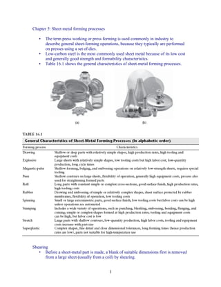
  • 1. Chapter 5: Sheet metal forming processes • The term press working or press forming is used commonly in industry to describe general sheet-forming operations, because they typically are performed on presses using a set of dies. • Low-carbon steel is the most commonly used sheet metal because of its low cost and generally good strength and formability characteristics. • Table 16.1 shows the general characteristics of sheet-metal forming processes. Shearing • Before a sheet-metal part is made, a blank of suitable dimensions first is removed from a large sheet (usually from a coil) by shearing. 1
  • 2. Fig 16.2 (a) shows schematic illustration of shearing with a punch and die, indicating some of the process variables. Characteristic features of (b) a punched hole; (c) the slug. • The rough fracture surfaces are due to these cracks; the smooth and shiny burnished surfaces on the hole and the slug are from the contact and rubbing of the sheared edge against the walls of the punch and die, respectively. • The major processing parameters in shearing are 1. The shape of the punch and die 2. The speed of punching 3. Lubrication 4. The clearance, c, between the punch and the die As the clearance increases, the material tends to be pulled into the die rather than be sheared. In practice, clearances usually range between 2 and 10% of the thickness of the sheet. Punch force • The force required to punch is basically the product of the shear strength of the 2
  • 3. sheet metal and the total area being sheared along the periphery. • The maximum punch force, F, can be estimated from the equation F = 0.7TL( UTS ) (16.1) where T is the sheet thickness, L is the total length sheared (such as the perimeter of a hole), and UTS is the ultimate tensile strength of the material. • Friction between the punch and the work piece can, however, increase punch force significantly. • Furthermore, in addition to the punch force, a force is required to strip the punch from the sheet during its return stroke. Example 16.1 Calculation of punch force Estimate the force required for punching a 25-mm diameter hole through a 3.2-mm thick annealed titanium-alloy Ti-6Al-4V sheet at room temperature. Solution The force is estimated from Eq. (16.1) where the UTS for this alloy is found from Table 6.10 to be 1000 MPa. Thus, F = 0.7( 3.2 )(π )( 25)(1000 ) = 0.18 MN Shearing Operations • The most common shearing operations are punching—where the sheared slug is scrap or may be used for some other purpose—and blanking—where the slug is the part to be used and the rest is scrap. • Fig 16.4 (a) shows punching (piercing) and blanking, while (b) shows the examples of various die-cutting operations on sheet metal. • This is a shearing operation that consists of the following basic processes: 1. Perforating: punching a number of holes in a sheet 2. Parting: shearing the sheet into two or more pieces 3. Notching: removing pieces (or various shapes) from the edges 4. Lancing: leaving a tab without removing any material Fine blanking • Very smooth and square edges can be produced by fine blanking. 3
  • 4. Fig 16.5(a) shows the comparison of sheared edges produced by conventional (left) and by fine-blanking (right) techniques and (b) shows schematic illustration of one setup for fine blanking. Slitting • In slitting, the blades follow either a straight line, a circular path, or a curved path. • Fig 16.6 shows the slitting with rotary knives. • This process is similar to opening cans. Steel rules • Soft metals (as well as paper, leather, and rubber) can be blanked with a steel-rule die. 4
  • 5. The die is pressed against the sheet which rests on the flat surface, and it shears the sheet along the shape of the steel rule. • Soft metals (as well as paper, leather, and rubber) can be blanked with a steel-rule die. • The die is pressed against the sheet which rests on the flat surface, and it shears the sheet along the shape of the steel rule. Characteristics and type of shearing dies Clearance • Because the formability of the sheared part can be influenced by the quality of its sheared edges, clearance control is important. • The appropriate clearance depends on 1. The type of material and its temper 2. The thickness and size of the blank 3. Its proximity to the edges of other sheared edges or the edges of the original blank As a general guideline, (a) clearances for soft materials are less than those for harder grades; (b) the thicker the sheet, the larger the clearance must be; and (c) as the ratio of hole diameter to sheet thickness decreases, clearances should be larger. Punch and Die • Both the surfaces of the punch and of the die are flat. • Because the entire thickness is sheared at the same time, the punch force increases rapidly during shearing. • The location of the regions being sheared at any particular instant can be controlled by beveling the punch and die surfaces. • Fig 16.10 shows the examples of the use of shear angles on punches and dies. Compound dies • Several operations on the same sheet may be performed in one stroke at one station with a compound die. • Such combined operations usually are limited to relatively simple shapes, because (a) the process is somewhat slow and (b) the dies rapidly become much more expensive to produce than those for individual shearing operations, especially for complex dies. 5
  • 6. 6
  • 7. Progressive dies • Parts requiring multiple operations to produce can be made at high production rates in progressive dies. • The sheet metal is fed through as a coil strip, and a different operation (such as punching, blanking, and notching) is performed at the same station of the machine with each stroke of a series of punches. Transfer dies • In a transfer-die setup, the sheet metal undergoes different operations at different stations of the machine which are arranged along a straight line or a circular path. • After each step in a station, the part is transferred to the next station for further operations. Tool and die materials • Tool and die materials for shearing generally are tool steels and (for high production rates) carbides. 7
  • 8. Lubrication is important for reducing tool and die wear, thus improving edge quality. Miscellaneous methods of cutting sheet metal • There are several other methods of cutting sheets and, particularly, plates: 1. Laser-beam cutting is an important process typically used with computer- controlled equipment to cut a variety of shapes consistently, in various thicknesses, and without the use of any dies. 2. Water-jet cutting is a cutting process that is effective on many metallic as well as nonmetallic materials. 3. Cutting with a band saw; this method is a chip-removal process. 4. Friction sawing involves a disk or blade which rubs against the sheet or plate at high surface speeds. 5. Flame cutting is another common method, particularly for thick plates; it is used widely in ship building and on heavy structural components. Bending sheets and plates • Bending is one of the most common industrial forming operations. • Fig 16.16 shows the bending terminology. Note that the bend radius is measured to the inner surface of the bent part. • Fig 16.17 (a) and (b) shows the effect of elongated inclusions (stringers) on cracking as a function of the direction of bending with respect to the original rolling direction of the sheet. (c) Cracks on the outer surface of an aluminum strip bent to an angle of 90°. 8
  • 9. The bend allowance, is the length of the neutral axis in the bend and is used to determine the length of the blank for a part to be bent. • An approximate formula for the bend allowance is given by Lb = α ( R + kT ) ( 16.2) where α is the bend angle (in radians), T is the sheet thickness, R is the bend radius, and k is a constant. Minimum bend radius • The radius at which a crack first appears at the outer fibers of a sheet being bent is referred to as the minimum bend radius. • It can be shown that the engineering strain on the outer and inner fibers of a sheet during bending is given by the expression 1 e= ( 16.4) ( 2R / T ) + 1 • Thus, as R/T decreases (that is, as the ratio of the bend radius to the thickness becomes smaller), the tensile strain at the outer fiber increases, and the material eventually develops cracks. • Table 16.3 shows the minimum bend radius for various materials at room temperature. • Fig 16.18 shows the relationship between R/T ratio and tensile reduction of area for sheet metals. Note that sheet metal with a 50% tensile reduction of area can be 9
  • 10. bent over itself in a process like the folding of a piece of paper without cracking. • The minimum bend radius, R, is, approximately,  50  R = T  − 1 (16.5)  r  where r is the tensile reduction of area of the sheet metal. • Another significant factor in edge cracking is the amount, shape, and hardness of inclusions present in the sheet metal and the amount of cold working that the edges undergo during shearing. • Anisotropy of the sheet is another important factor in bendability. • Cold rolling results in anisotropy by preferred orientation or by mechanical fibering due to the alignment of any impurities, inclusions, and voids that may be present. Springback • Because all materials have a finite modulus of elasticity, plastic deformation always is followed by some elastic recovery when the load is removed. • In bending, this recovery is called springback, which can be observed easily by bending and then releasing a piece of sheet metal or wire. • Fig 16.9 shows the springback in bending. The part tends to recover elastically after bending, and its bend radius becomes larger. Under certain conditions, it is possible for the final bend angle to be smaller than the original angle (negative springback). Reduce or eliminate springback • Fig 16.20 shows the methods of 10
  • 11. reducing or eliminating springback in bending operations. • Springback in forming operations usually is compensated for by overbending the part. • Coin the bend area by subjecting highly localized compressive stress between punch tip and die surface – bottoming • Stretch bending Bending force • The bending force for sheets and plates can be estimated by assuming that the process is one of the simple bending of a rectangular beam. • Excluding friction, the maximum bending force, P, is kYLT 2 P= ( 16.7) W where the factor k ranges from about 0.3 for a wiping die, to about 0.7 for a U-die. • For a V-die, Eq. (16.7) is often modified as P= ( UTS ) LT 2 ( 16.8) W where UTS is the ultimate tensile strength of the material. Various bending operations Press-brake forming • Sheets or narrow strips that are 7 m or even longer usually are bent in a press brake. • Fig 16.23(a) through (e) shows the schematic illustrations of various bending operations in a press brake, and (f) shows the schematic illustration of a press 11
  • 12. brake. • The process can be automated easily for low-cost, high-production runs. • Die materials for press brakes may range from hardwood (for low-strength materials and small-production runs) to carbides for strong and abrasive sheet materials and also are chosen to improve die life. Roll bending • In this process, plates are bent using a set of rolls. • By adjusting the distance between the three rolls, various curvatures can be obtained. • This process is flexible and is used widely for bending plates for applications such as boilers, cylindrical pressure vessels, and various curved structural members. 12
  • 13. Beading • In beading, the periphery of the sheet metal is bent into the cavity of a die. • The bead imparts stiffness to the part by increasing the moment of inertia of that section. • Also, beads improve the appearance of the part and eliminate exposed sharp edges that can be hazardous. • Fig 16.24(a) shows bead forming with a single die. (b) though (d) Bead forming with two dies in a press brake. Flanging • This is a process of bending the edges of sheet metals, usually to 90°. • In shrink flanging, the flange is subjected to compressive hoop stresses which, if excessive, can cause the flange periphery to wrinkle. • The wrinkling tendency increases with decreasing radius of curvature of the flange. • In stretch flanging, the flange periphery is subjected to tensile stresses that, if excessive, can lead to cracking along the periphery. 13
  • 14. Deep Drawing • Numerous parts made of sheet metal are cylindrical or box shaped, such as pots and pans, all types of containers for food and beverages, stainless-steel kitchen sinks, canisters, and automotive fuel tanks. • Fig 16.31 shows the metal-forming processes involved in manufacturing a two- piece aluminum beverage can. • The process generally is called deep drawing because of its capability for producing deep parts) • It also is used to make parts that are shallow or have moderate depth and is one of the most important metalworking processes because of the wide use of products made. • Fig 16.32(a) shows the schematic illustration of the deep-drawing process on a circular sheet-metal blank. • The stripper ring facilitates the removal of the formed cup from the punch. • Fig 16.32(b) shows the process variables in deep drawing. • Except for the punch force, F, all the parameters indicated in the figure are independent variables. • The maximum punch force, Fmax can be estimated from the formula 14
  • 15. [ Fmax = πD pT (UTS ) ( Do / D p ) − 0.7 ] (16.9) 15
  • 16. Deep drawability • In a deep-drawing operation, failure generally results from the thinning of the cup wall under high longitudinal tensile stresses. • Deep drawability generally is expressed by the limiting drawing ratio (LDR), as Maximum blank diameter Do LDR = = (16.10) Punch diameter Dp • Whether a sheet metal can be deep drawn successfully into a round cup-shaped part has been found to be a function of the normal anisotropy, R, of the sheet metal (also called plastic anisotropy). • Normal anisotropy is defined in terms of the true strains that the specimen undergoes in tension: Width strain ε R= = w (16.11) Thickness strain ε t • An average value, Ravg, is calculated from the equation R + 2R + R Ravg = 0 45 90 ( 16.12) 4 • Some typical values of Ravg are given in Table 16.4. 16
  • 17. Earing • In drawing, the edges of cups may become wavy—a phenomenon called earing. • Fig 16.35 shows the earing in a drawn steel cup caused by the planar anisotropy of the sheet metal. Deep-drawing practice • Draw beads often are necessary to control the flow of the blank into the die cavity. • Fig 16.36(a) shows schematic illustration of a draw bead. (b) Metal flow during the drawing of a box-shaped part while using beads to control the movement of the material. (c) Deformation of circular grids in the flange in deep drawing. • Draw beads also are useful in drawing box-shaped and nonsymmetric parts, because they can present significant difficulties in practice. • In order to avoid tearing of the sheet metal during forming, it often is necessary to incorporate the following factors: 1. Proper design and location of draw beads 17
  • 18. 2. Large die radii 3. Effective lubrication 4. Proper blank size and shape 5. The cutting off of corners of square or rectangular blanks at 45° to reduce tensile stresses developed during drawing 6. The use of blanks free of internal and external defects Ironing • Note in Fig. 16.32 that if the clearance between the punch and the die is sufficiently large, the drawn cup will have thicker walls at its rim than at its base. • The reason for this is that the cup rim consists of material from the outer diameter of the blank, hence it has been reduced in diameter more (and thus becomes thicker) than the material constituting the rest of the cup wall. Redrawing • Containers that are too difficult to draw in one operation generally undergo redrawing. • Because of the volume constancy of the metal, the cup becomes longer as it is redrawn to smaller diameters. • In reverse redrawing, the cup is placed upside down in the die and thus is subjected to bending in the direction opposite to its original configuration. Drawing without blankholder • Deep drawing also may be carried out successfully without a blankholder, provided that the sheet metal is sufficiently thick to prevent wrinkling. • A typical range of the diameter is Do − D p < 5T (16.14) where T is the sheet thickness. Tooling and equipment for drawing • The most common tool and die materials for deep drawing are tool steels and cast irons and include dies produced from ductile iron castings made by the lost-foam process. • The equipment for deep drawing is usually a double-action hydraulic press or a mechanical press, the latter generally being favored because of its higher operating speed. Rubber Forming • Polyurethanes are used widely because of their 1. Resistance to abrasion 2. Resistance to cutting or tearing by burrs or other sharp edges on the sheet metal 3. Long fatigue life • In the bending and embossing of sheet metal by this process, the female die is replaced with a rubber pad. • Fig 16.39 shows the examples of the bending and the embossing of sheet metal with a metal punch and with a flexible pad serving as the female die. 18
  • 19. In the hydroform or fluid-forming process, the pressure over the rubber membrane is controlled throughout the forming cycle with a maximum pressure of up to 100 MPa. • Fig 16.40 shows the the hydroform (or fluid-forming) process. Note that in contrast to the ordinary deep drawing process, the pressure in the dome forces the cup walls against the punch. The cup travels with the punch; in this way, deep drawability is improved. When selected properly, rubber-forming and hydroforming processes have the advantages of (a) the capability to form complex shapes, (b) forming parts with laminated sheets of various materials and coatings, (c) flexibility and ease of operation, (d) the avoidance of damage to the surfaces of the sheet, (e) low die wear, and (f) low tooling cost. 19
  • 20. Spinning • Spinning is a process which involves the forming of axisymmetric parts over a mandrel by the use of various tools and rollers—a process that is similar to that of forming clay on a potter’s wheel. Conventional spinning • In conventional spinning, a circular blank of flat or preformed sheet metal is placed and held against a mandrel and rotated while a rigid tool deforms and shapes the material over the mandrel. • Fig 16.42(a) shows the schematic illustration of the conventional spinning process. (b) Types of parts conventionally spun. All parts are axisymmetric • Although most spinning is performed at room temperature, thick parts and metals with high strength or low ductility require spinning at elevated temperatures Shear spinning • The spinnability of a metal in this process generally is defined as the maximum reduction in thickness to which a part can be subjected by spinning without fracture. • For metals with low ductility, the operation is carried out at elevated temperatures by heating the blank in a furnace and transferring it rapidly to the mandrel. 20
  • 21. Tube spinning • In tube spinning, the thickness of hollow, cylindrical blanks is reduced or shaped by spinning them on a solid, round mandrel using rollers. • The reduction in wall thickness results in a longer tube. • Tube spinning can be used to make rocket, missile, and jet engine parts, pressure vessels, and automotive components, such as car and truck wheels. 21
  • 22. Tube spinning • In tube spinning, the thickness of hollow, cylindrical blanks is reduced or shaped by spinning them on a solid, round mandrel using rollers. • The reduction in wall thickness results in a longer tube. • Tube spinning can be used to make rocket, missile, and jet engine parts, pressure vessels, and automotive components, such as car and truck wheels. 21
  • 23. Tube spinning • In tube spinning, the thickness of hollow, cylindrical blanks is reduced or shaped by spinning them on a solid, round mandrel using rollers. • The reduction in wall thickness results in a longer tube. • Tube spinning can be used to make rocket, missile, and jet engine parts, pressure vessels, and automotive components, such as car and truck wheels. 21