BMU (Building Maintenance Unit)
•
7 likes•6,020 views

Anatomy of a a building maintenance unit

Recommended
More Related Content
What's hot
What's hot (20)
Viewers also liked
Viewers also liked (19)
Similar to BMU (Building Maintenance Unit)
Similar to BMU (Building Maintenance Unit) (20)
Recently uploaded
Recently uploaded (20)
BMU (Building Maintenance Unit)
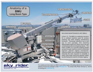
- 1. Anatomy of a BMU Long Boom Type Slewing Gearmotor Base Frame Control Panel Hydraulic Ram Motorized Trolley Luffing Boom Counterweight Hydraulic Powerpack Operating ControlsHoisting Assembly Slewing Limit Knuckle Boom Jib and Spreader Bar Telescoping Gearmotor Platform BUILDING MAINTENANCE UNIT(BMU): In the U. S., The BMU is a relatively new term for a unitized machine used for window washing and other building maintenance functions. Previously referred to as a roof car or roof carriage, this machine differentiates itself from others due to its self contained and all-encompasing nature. The intent of BMU is to provide building facade access through machine control to eliminate rigorous manual rigging procedures. Utilizing a BMU can increase productivity by reducing the time required to complete a wash cycle while improving operator safety by eliminating the need for complex rigging. For additional information on BMU's and other types of Building Mantenance Equipment, please browse this website under . To contact Sky Rider directly by phone or email go to . PROJECTS CONTACTSequipment co., inc. The Carlyle
- 2. Operating Controls Wire Rope Guide Auxiliary Hoist Auxiliary Hoist Guide Sheaves Base Frame Hoisting Assembly Motorized Trolley Counterweight Boom Lighting Entry Steps equipment co., inc. Anatomy of a BMU Twin Boom Type City National
- 3. Standard Platform Approach Platform "Goal Post" Platform & BMU Bumper Rollers Stabilization Pins Counterweight Obstruction Bar Entry Steps equipment co., inc. Anatomy of a BMU Platform Types Hydraulic Ram Twin Boom BMU New Otani TD Tower The Carlyle
- 4. The basic components of the BMU are described as follows: On an Approach Platform, the counterweight extends outward, while the Platform extends toward the facade. Rams are also used on Approach type Platforms and for vertical telescoping Masts. APPROACH PLATFORM: A Platform that utilizes a pantographic style supporting frame, Hydraulic Ram and Counterweight to "approach" the facade in conditions where the facade is resessed (i.e. below a soffit) and where the suspension wire ropes must remain at a fixed distance. BASE FRAME: In these illustrations, the Base Frame is supported by Motorized Trolleys which allows it to travel on a track. The Base Frame may also be mounted permanently to a fixed structure on the building. CONTROL PANEL: The Control Panel houses the electrical control circuitry in a weather tight enclosure. COUNTERWEIGHT: Counterweight is used to counteract the combined load of the outstretched Boom, Platform dead weight and Platform live (rated) load. It prevents uplift on the Base Frame in all operating conditions. HOISTING ASSEMBLY: An enclosure that contains the Multilayer Drum on which the wire ropes are stored, Hoisting Gearmotor, Wire Rope Levelwind system and communications system termination. HYDRAULIC POWERPACK: The Hydraulic Power pack is a self contained system that contains a pump, reservoir and solenoid valves feeding the Hydraulic Ram to raise and lower (Luff) the Boom. HYDRAULIC RAM: As noted above, the Ram is controlled by the Hydraulic Power pack and is connected between the Boom and the Main Frame. JIB: The Jib acts as an extension of the Boom. On the illustrated Long Boom BMU, it rotates with respect to the Knuckle Boom and supports the Spreader Bar. KNUCKLE BOOM: Used as a means to allow additional flexibility to the boom for positioning of the platform or to aid in positioning or parking. The Knuckle Boom is similar in operation to the Jib and the terms are often used interchangeably. LUFFING BOOM: In this application, the Boom is raised and lowered (Luffed) due to the action of the Hydraulic Ram. Twin Boom BMU's can be luffed by either Hydraulic means or by motorized screw. MOTORIZED TROLLEY: Supported by the Base Frame and traveling on the Track, the Motorized Trolleys position the BMU laterally around the perimeter of the building. OBSTRUCTION BAR: Building features are difficult to observe while descending in the platform. The Obstruction Bar will stop downward travel when a obstruction is reached. OPERATING CONTROLS: Acting as a pendant, the operating control panel is detachable to allow the operator freedom to move about the area around the BMU for ease of positioning. Typically, all of the platform controls are duplicated on this panel. PLATFORM: Generally constructed of aluminum with a steel framework, the platform supports the worker(s) as it moves about the building. SLEWING GEARMOTOR: Operating against a large ring gear mounted to the Base Frame, the gearmotor allows rotation (slewing) of the BMU independent of the orientation of the Base Frame. SLEWING LIMIT: This device acts as a horizontal obstruction bar. Should the boom come in contact with a building member, the obstruction bar will stop the slewing motion in that direction of travel. SPREADER BAR: Routes the wire ropes outward from the Jib to match the suspension points of the Platform.