
Recomendados
Recomendados
Más contenido relacionado
La actualidad más candente
La actualidad más candente (20)
Similar a MANUAL ENGINE RHZ PSA 2.0 TURBO.pdf
Similar a MANUAL ENGINE RHZ PSA 2.0 TURBO.pdf (20)
Más de jorgemaganinho1
Último
Último (8)
MANUAL ENGINE RHZ PSA 2.0 TURBO.pdf
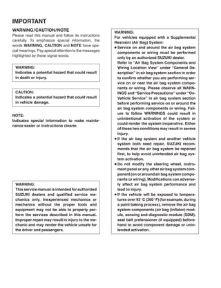
- 1. WARNING: For vehicles equipped with a Supplemental Restraint (Air Bag) System: D Service on and around the air bag system components or wiring must be performed only by an authorized SUZUKI dealer. Refer to “Air Bag System Components and Wiring Location View” under “General De- scription” in air bag system section in order to confirm whether you are performing ser- vice on or near the air bag system compo- nents or wiring. Please observe all WARN- INGS and “Service Precautions” under “On- Vehicle Service” in air bag system section before performing service on or around the air bag system components or wiring. Fail- ure to follow WARNINGS could result in unintentional activation of the system or could render the system inoperative. Either of these two conditions may result in severe injury. D If the air bag system and another vehicle system both need repair, SUZUKI recom- mends that the air bag system be repaired first, to help avoid unintended air bag sys- tem activation. D Do not modify the steering wheel, instru- ment panel or any other air bag system com- ponent (on or around air bag system compo- nents or wiring). Modifications can adverse- ly affect air bag system performance and lead to injury. D If the vehicle will be exposed to tempera- tures over 93_C (200_F) (for example, during a paint baking process), remove the air bag system components (air bag (inflator) mod- ule, sensing and diagnostic module (SDM), seat belt pretensioner (if equipped) before- hand to avoid component damage or unin- tended activation. IMPORTANT WARNING/CAUTION/NOTE Please read this manual and follow its instructions carefully. To emphasize special information, the words WARNING, CAUTION and NOTE have spe- cial meanings. Pay special attention to the messages highlighted by these signal words. NOTE: Indicates special information to make mainte- nance easier or instructions clearer. WARNING: Indicates a potential hazard that could result in death or injury. CAUTION: Indicates a potential hazard that could result in vehicle damage. WARNING: This service manual is intended for authorized SUZUKI dealers and qualified service me- chanics only. Inexperienced mechanics or mechanics without the proper tools and equipment may not be able to properly per- form the services described in this manual. Improper repair may result in injury to the me- chanic and may render the vehicle unsafe for the driver and passengers.
- 2. ( x ) ( x ) FOREWORD This manual is a supplement to SQ416/SQ420/SQ625 SERVICE MANUAL. It has been pre- pared exclusively for the following applicable model. Applicable model: SQ420WD (GRAND VITARA RHZ Diesel engine model) on and after the following VIN No. JSAFTD82V00100001 X It described only different servicing information of SQ420WD RHZ engine model as compared with SQ416/SQ420/ SQ625. Therefore, whenever servicing SQ420WD, consult this service manual first. And for any section, item or description not found in this service manual, refer to the related manuals below. When replacing parts or servicing by disassembling, it is recommended to use SUZUKI genuine parts, tools and service materials (lubricant, sealants, etc.) as specified in each description. All information, illustrations and specifications contained in this literature are based on the latest product information available at the time of publication approval. And used as the main subject of description is the vehicle of standard specifications among others. Therefore, note that illustrations may differ from the vehicle being actually serviced. The right is reserved to make changes at any time without notice. RELATED MANUALS: Manual Name Manual No. SQ416/SQ420/SQ625 Service Manual (Volume 1 and 2) 99500-65D10-XXX GRAND VITARA SUPPLEMENTARY SERVICE MANUAL 99501-65D30-XXX SQ416/SQ420/SQ625 Unit Repair Manual (For Manual Transmission, Automatic Transmission, Transfer and Differential.) 99501-65D01-XXX SQ416/SQ420/SQ625 Wiring Diagram Manual 99512-65D11-015 SQ420WD Supplementary Wiring Diagram Manual 99512-68D10-015 COPYRIGHT SUZUKI MOTOR CORPORATION 2002
- 3. 0A 0B 1A 3B1 3E 4A2 4B 6 6A3 6B 6C 6E3 6G 6H 6K 7A2 7B1 7C1 7E 7F 8C 8G 1B 6-1 ENGINE Engine General Information and Diagnosis (RHZ Engine With Single-connector ECM) Engine General Information and Diagnosis (RHZ Engine With Triple-connector ECM) Engine Mechanical (RHZ engine) Engine Cooling Engine Fuel Engine and Emission Control System (RHZ engine) Cranking System (2.0 kw Reduction Type) Charging System Exhaust System HEATING AND AIR CONDITIONING Heater and Ventilation Air Conditioning BODY ELECTRICAL SYSTEM Instrumentation/Driver Information Immobilizer Control System TABLE OF CONTENTS SECTION GENERAL INFORMATION General Information Maintenance and Lubrication STEERING, SUSPENSION, WHEELS AND TIRES Power Steering (P/S) System Rear Suspension DRIVE SHAFT/PROPELLER SHAFT Front Drive Shaft/Shaft Bearing, Oil Seal Propeller Shafts 0A 0B 1B 3B1 4A2 6 6A3 6B 6C 6E3 6G 6H 6K 7A2 7C1 7F 8C 8G TRANSMISSION, CLUTCH AND DIFFERENTIAL Manual Transmission Automatic Transmission Clutch (Hydraulic Type) Differential (Front) Differential (Rear) 3E 4B 7B1 7E 1A 6-1
- 4. 0A GENERAL INFORMATION 0A-1 SECTION 0A GENERAL INFORMATION NOTE: For the descriptions (items) not found in this section, refer to the same section of the Service Manual men- tioned in FOREWORD of this manual. CONTENTS PRECAUTIONS 0A- 2 . . . . . . . . . . . . . . . . . . . . . . . . . . . . . . . . . . . . . . . . . . . . . . . . . . . . . . . . . . . . . . . . . . . . . . . . . . . . General Precautions 0A- 2 . . . . . . . . . . . . . . . . . . . . . . . . . . . . . . . . . . . . . . . . . . . . . . . . . . . . . . . . . . . . . . . . . . . . . . IDENTIFICATION INFORMATION 0A- 5 . . . . . . . . . . . . . . . . . . . . . . . . . . . . . . . . . . . . . . . . . . . . . . . . . . . . . . . . . . . . Vehicle Identification Number 0A- 5 . . . . . . . . . . . . . . . . . . . . . . . . . . . . . . . . . . . . . . . . . . . . . . . . . . . . . . . . . . . . . . Engine Identification Number 0A- 5 . . . . . . . . . . . . . . . . . . . . . . . . . . . . . . . . . . . . . . . . . . . . . . . . . . . . . . . . . . . . . . . Transmission Identification Number 0A- 5 . . . . . . . . . . . . . . . . . . . . . . . . . . . . . . . . . . . . . . . . . . . . . . . . . . . . . . . . . WARNING, CAUTION AND INFORMATION LABELS 0A- 6 . . . . . . . . . . . . . . . . . . . . . . . . . . . . . . . . . . . . . . . . . . FASTENER INFORMATION 0A- 7 . . . . . . . . . . . . . . . . . . . . . . . . . . . . . . . . . . . . . . . . . . . . . . . . . . . . . . . . . . . . . . . . . Metric Fasteners 0A- 7 . . . . . . . . . . . . . . . . . . . . . . . . . . . . . . . . . . . . . . . . . . . . . . . . . . . . . . . . . . . . . . . . . . . . . . . . .
- 5. 0A-2 GENERAL INFORMATION PRECAUTIONS GENERAL PRECAUTIONS The WARNING and CAUTION below describe some general precautions that you should observe when servicing a vehicle. These general precautions apply to many of the service procedures described in this manual, and they will not necessarily be repeated with each procedure to which they apply. WARNING: D Whenever raising a vehicle for service, be sure to follow the instructions under “VEHICLE LIFTING POINTS” on SECTION 0A. D When it is necessary to do service work with the engine running, make sure that the parking brake is set fully and the transmission is in Neutral (for manual transmission vehicles) or Park (for automatic transmission vehicles). Keep hands, hair, clothing, tools, etc. away from the fan, belts and fuel line between high pressure fuel pump and injectors when the engine is running. D When it is necessary to run the engine indoors, make sure that the exhaust gas is forced outdoors. D Do not perform service work in areas where combustible materials can come in contact with a hot exhaust system. When working with toxic or flammable materials (such as gasoline and refrigerant), make sure that the area you work in is well-ventilated. D To avoid getting burned, keep away from hot metal parts such as the radiator, exhaust manifold, tail- pipe, muffler, etc. D New and used engine oil can be hazardous. Children and pets may be harmed by swallowing new or used oil. Keep new and used oil and used engine oil filters away from children and pets. Continuous contact with used engine oil has been found to cause [skin] cancer in laboratory animals. Brief contact with used oil may irritate skin. To minimize your exposure to used engine oil, wear a long-sleeve shirt and moisture-proof gloves (such as dishwashing gloves) when changing engine oil. If engine oil contacts your skin, wash thoroughly with soap and water. Launder any clothing or rags if wet with oil, recycle or properly dispose of used oil and filters. D Make sure the bonnet is fully closed and latched before driving. If it is not, it can fly up unexpectedly during driving, obstructing your view and resulting in an accident. CAUTION: D Before starting any service work, cover fenders, seats and any other parts that are likely to get scratched or stained dur- ing servicing. Also, be aware that what you wear (e.g, but- tons) may cause damage to the vehicle’s finish. D When performing service to electrical parts that does not re- quire use of battery power, disconnect the negative cable of the battery.
- 6. GENERAL INFORMATION 0A-3 “A” D When removing the battery, be sure to disconnect the nega- tive cable first and then the positive cable. When reconnect- ing the battery, connect the positive cable first and then the negative cable, and replace the terminal cover. D When removing parts that are to be reused, be sure to keep them arranged in an orderly manner so that they may be rein- stalled in the proper order and position. D Whenever you use oil seals, gaskets, packing, O-rings, lock- ing washers, split pins, self-locking nuts, and certain other parts as specified, be sure to use new ones. Also, before installing new gaskets, packing, etc., be sure to remove any residual material from the mating surfaces. D Make sure that all parts used in reassembly are perfectly clean. D When use of a certain type of lubricant, bond or sealant is specified, be sure to use the specified type. “A”: Sealant 99000-31150 D Be sure to use special tools when instructed. Special Tool (A): 09917-98221 (B): 09916-58210
- 7. 0A-4 GENERAL INFORMATION D When disconnecting vacuum hoses, attach a tag describing the correct installation positions so that the hoses can be re- installed correctly. D After servicing fuel, oil, coolant, vacuum, exhaust or brake systems, check all lines related to the system for leaks. D For vehicles equipped with fuel injection systems, never dis- connect the fuel line between the fuel pump and injector within 30 sec. after engine stop, or fuel can be sprayed out under pressure.
- 8. 4-speed A/T M/T GENERAL INFORMATION 0A-5 IDENTIFICATION INFORMATION VEHICLE IDENTIFICATION NUMBER The number is punched on the chassis inside the tire housing on the right front side. ENGINE IDENTIFICATION NUMBER The number is punched on the cylinder block. TRANSMISSION IDENTIFICATION NUMBER The number is located on the transmission case.
- 9. NOTE: Air bag CAUTION/WARNING labels are attached on the vehicle equipped with air bag system only. 1. Air bag label 2. Smoke level label 3. Air bag label on sun visor 4. Radiator cooling fan label 5. Degassing tank cap (radiator cap) label 6. Transfer label 7. Air bag label on wire harness 8. Air bag label on passenger air bag (inflator) module 9. Seat belt pretensioner label on retractor 10. Air bag label on SDM 11. Air bag label on driver air bag (inflator) module 12. Air bag label on combination switch and contact coil assembly 13. Air bag label on steering column 0A-6 GENERAL INFORMATION WARNING, CAUTION AND INFORMATION LABELS The figure below shows main labels among others that are attached to vehicle component parts. When servicing and handling parts, refer to WARNING/CAUTION instructions printed on labels. If any WARNING/CAUTION label is found stained or damaged, clean or replace it as necessary.
- 10. 1. Diameter 2. Pitch GENERAL INFORMATION 0A-7 FASTENER INFORMATION METRIC FASTENERS Most of the fasteners used for this vehicle are metric fasteners. When replacing any fasteners, it is most important that replacement fasteners be the correct diameter, thread pitch and strength. CAUTION: Note that both ISO and JIS type bolts and nuts are used for the engine assembly and related parts. Even when the diam- eter of the thread is the same, its pitch may vary between these two types. Installing a mismatched bolt or nut will cause damage to the thread. As the first step, make sure to tighten it by hand temporarily and if it feels tight, check the thread pitch for correct matching.
- 11. 0B MAINTENANCE AND LUBRICATION 0B-1 SECTION 0B MAINTENANCE AND LUBRICATION WARNING: For vehicles equipped with Supplemental Restraint (Air Bag) System: D Service on and around the air bag system components or wiring must be performed only by an autho- rized SUZUKI dealer. Refer to “Air Bag System Components and Wiring Location View” under “Gener- al Description” in air bag system section in order to confirm whether you are performing service on or near the air bag system components or wiring. Please observe all WARNINGS and “Service Precau- tions” under “On-Vehicle Service” in air bag system section before performing service on or around the air bag system components or wiring. Failure to follow WARNINGS could result in unintentional activation of the system or could render the system inoperative. Either of these two conditions may result in severe injury. D Technical service work must be started at least 90 seconds after the ignition switch is turned to the “LOCK” position and the negative cable is disconnected from the battery. Otherwise, the system may be activated by reserve energy in the Sensing and Diagnostic Module (SDM). NOTE: For the descriptions (items) not found in this section, refer to the same section of the Service Manual men- tioned in FOREWORD of this manual. CONTENTS MAINTENANCE SCHEDULE 0B- 2 . . . . . . . . . . . . . . . . . . . . . . . . . . . . . . . . . . . . . . . . . . . . . . . . . . . . . . . . . . . . . . . . Maintenance Schedule Under Normal Driving Conditions 0B- 2 . . . . . . . . . . . . . . . . . . . . . . . . . . . . . . . . . . . . . . Maintenance Recommended Under Severe Driving Conditions 0B- 4 . . . . . . . . . . . . . . . . . . . . . . . . . . . . . . . . . MAINTENANCE SERVICE 0B- 5 . . . . . . . . . . . . . . . . . . . . . . . . . . . . . . . . . . . . . . . . . . . . . . . . . . . . . . . . . . . . . . . . . . Engine 0B- 5 . . . . . . . . . . . . . . . . . . . . . . . . . . . . . . . . . . . . . . . . . . . . . . . . . . . . . . . . . . . . . . . . . . . . . . . . . . . . . . . . . . Fuel System 0B- 9 . . . . . . . . . . . . . . . . . . . . . . . . . . . . . . . . . . . . . . . . . . . . . . . . . . . . . . . . . . . . . . . . . . . . . . . . . . . . . Chassis and Body 0B-11 . . . . . . . . . . . . . . . . . . . . . . . . . . . . . . . . . . . . . . . . . . . . . . . . . . . . . . . . . . . . . . . . . . . . . . . . RECOMMENDED FLUIDS AND LUBRICANTS 0B-13 . . . . . . . . . . . . . . . . . . . . . . . . . . . . . . . . . . . . . . . . . . . . . . . .
- 12. 0B-2 MAINTENANCE AND LUBRICATION MAINTENANCE SCHEDULE MAINTENANCE SCHEDULE UNDER NORMAL DRIVING CONDITIONS Interval: This interval should be judged by This table includes services as scheduled up to 90,000 km (54,000 miles) mileage. Beyond 90,000 km (54,000 miles), carry out the same services at the same intervals respectively. j g y odometer reading or months, Km (x 1,000) 15 30 45 60 75 90 whichever comes first. Miles (x 1,000) 9 18 27 36 45 54 Months 12 24 36 48 60 72 1. ENGINE 1-1. Accessory drive belt – – I – – R 1-2. Camshaft timing belt Replace every 150,000 km (90,000 miles). 1-3. Engine oil and oil filter Replace every 20,000 km (12,000 miles) or 16 months. 1-4. Engine coolant – – R – – R 1-5. Exhaust system – I – I – I 1-6. Heater (Glow) plugs Inspect every 120,000 km (72,000 miles) or 96 months. 3. FUEL SYSTEM 3-1. Air cleaner filter I I R I I R 3-2. Fuel lines – I – I – I 3-3. Fuel filter Replace every 60,000 km (36,000 miles). Drain water every 20,000 km (12,000 miles). 3-4. Fuel tank – – I – – I
- 13. MAINTENANCE AND LUBRICATION 0B-3 Interval: This interval should be judged by This table includes services as scheduled up to 90,000 km (54,000 miles) mileage. Beyond 90,000 km (54,000 miles), carry out the same services at the same intervals respectively. This interval should be judged by odometer reading or months, Km (x 1,000) 15 30 45 60 75 90 g whichever comes first. Miles (x 1,000) 9 18 27 36 45 54 Months 12 24 36 48 60 72 CHASSIS AND BODY 6-1. Clutch (pedal and fluid level) – I – I – I 6-2. Brake discs and pads (thickness, wear, damage) I I I I I I Brake drums and shoes (wear, damage) – I – I – I 6-3. Brake hoses and pipes (leakage, damage, clamp) – I – I – I 6-4. Brake fluid – R – R – R 6-5. Brake lever and cable (damage, stroke, operation) Inspect at first 15,000 km (9,000 miles) only 6-6. Tires (wear, damage, rotation) I I I I I I 6-7. Wheel discs (damage) I I I I I I 6-8. Suspension system (tightness, damage, rattle, breakage) – I – I – I 6-9. Propeller shafts and drive shafts – – I – – I 6-10.Manual transmission oil (leakage, level) (I: 1st 15,000 km only) I – R – – R 6-11.Automatic transmission Fluid level – I – I – I Fluid change Replace every 165,000 km (99,000 miles) Fluid hose – – – R – – 6-12.Transfer oil (leakage, level) I – I – I – 6-13.Differential oil (leakage, level) (R: 1st 15,000 km only) R or I – I – I – 6-14.Steering system (tightness, damage, breakage, rattle) – I – I – I 6-15.Power steering (if equipped) I I I I I I 6-16.All latches, hinges and locks – I – I – I 6-17.Air conditioning filter (if equipped) – I R – I R NOTES: “R”: Replace or change “I” : Inspect and correct, replace or lubricate if necessary Some maintenance items are required to be serviced at times other than the regular maintenance times shown at the top of above table. These items can be serviced at an earlier service opportunity according to customer’s maintenance convenience. Their next maintenance service should be done within the speci- fied period.
- 14. 0B-4 MAINTENANCE AND LUBRICATION MAINTENANCE RECOMMENDED UNDER SEVERE DRIVING CONDITIONS If the vehicle is usually used under the conditions corresponding to any severe condition code given below, it is rec- ommended that applicable maintenance operation be performed at the particular interval as given in the chart below. Severe condition code A – Repeated short trips F – Leaded fuel use B – Driving on rough and/or muddy roads G – Town use/Towing a trailer/Sustained high speed C – Driving on dusty roads driving/Hot climates, frequently above 30_C(86_F)/ D – Driving in extremely cold weather Cold climates, frequently below –15_C (5_F)/Low and/or salted roads quality lubricants or fuel E – Repeated short trips in extremely H – Trailer towing (if admitted) cold weather Severe Condition Code Maintenance Maintenance Operation Maintenance Interval – B C D – – – – ITEM 1-1 I Every 15,000 km (9,000 miles) or 12 months – B C D – – – – Accessory drive belt (V-rib belt) R Every 45,000 km (27,000 miles) or 36 months A – C D E – G – ITEM 1-2 Camshaft timing belt R Every 120,000 km (72,000 miles) A – C D E F G H ITEM 1-3 Engine oil and oil filter R Every 5,000 km (3,000 miles) or 4 months – B – – – – – – ITEM 1-5 Exhaust pipe mountings I Every 15,000 km (9,000 miles) or 12 months – – C – – – – – ITEM 3-1 I Every 2,500 km (1,500 miles) – – C – – – – – Air cleaner filter*1 R Every 30,000 km (18,000 miles) or 24 months – – C – – – G – ITEM 3-3 Fuel filter R Every 10,000 km (6,000 miles) or 8 months – B C D – – – H ITEM 6-7 Wheel bearing I Every 15,000 km (9,000 miles) or 12 months – B – – – – – – ITEM 6-8 Suspension bolts and nuts T Every 15,000 km (9,000 miles) or 12 months – B – D E – – H ITEM 6-9 Propeller shafts and drive shafts I Every 15,000 km (9,000 miles) or 12 months – B – – E – – H ITEM 6-10, 6-12, 6-13 Manual transmission, transfer and differential oil R Every 30,000 km (18,000 miles) or 24 months – B – – E – – H ITEM 6-11 Automatic transmission fluid R Every 30,000 km (18,000 miles) or 24 months – – C D – – – – ITEM 6-17 Air conditioning filter *2 I Every 15,000 km (9,000 miles) or 12 months – – C D – – – – Air conditioning filter 2 (if equipped) R Every 45,000 km (27,000 miles) or 36 months NOTES: “I” : Inspect and correct, replace or lubricate if necessary “R” : Replace or change “T” : Tighten to the specified torque *1 : Inspect or replace more frequently if necessary. *2 : Clean or replace more frequently if the air from the air conditioning decreases.
- 15. 3. Zero wear mark MAINTENANCE AND LUBRICATION 0B-5 MAINTENANCE SERVICE ENGINE ITEM 1-1 Accessory Drive Belt Inspection and Replacement WARNING: All inspection and replacement are to be performed with ENGINE NOT RUNNING. Inspection 1) Disconnect negative cable at battery. 2) Inspect belt for cracks, cuts, deformation, wear and cleanliness using mirror under enough lighting. If any defect exists, replace. 3) Check that belt wear check mark (1) (tension indicator) is within range “a” using mirror (4) under enough lighting. If wear check mark (1) is aligned with maximum wear mark (2) or out of range “a” passing mark (2), replace accessory drive belt with a new one. 4) Connect negative cable to battery. Replacement Replace belt with a new one referring to GENERATOR in section 6H.
- 16. 1. Oil filter 0B-6 MAINTENANCE AND LUBRICATION ITEM 1-2 Camshaft Timing Belt Replacement Replace belt with new one. Refer to “Timing Belt” in SECTION 6A3 for replacement procedure. CAUTION: D Do not bend or twist timing belt. D Do not allow timing belt to come into contact with oil, wa- ter, etc. ITEM 1-3 Engine Oil and Oil Filter Change It is recommended to use the following engine oil or higher quality level oils. 5W-30 : API CF (except CF-2) or ACEA B3-98 15W-40: API SG/CF (except CF-2) or ACEA B2-96 Select the appropriate oil viscosity according to the left chart. Before draining engine oil, check engine for oil leakage. If any evi- dence of leakage is found, make sure to correct defective part be- fore performing the following work. 1) Drain engine oil by removing drain plug (1). 2) After draining oil, wipe drain plug clean. Reinstall drain plug, and tighten it securely as specified below. Tightening Torque (a): 34 N.m (3.4 kg-m, 25.0 lb-ft) 3) Loosen oil filter by using oil filter wrench (Special tool). Special Tool (A): 09915-46510
- 17. 1. Oil filter 1. LOW level mark 2. FULL level mark MAINTENANCE AND LUBRICATION 0B-7 4) Apply engine oil to new oil filter O-ring. 5) Screw new filter on oil filter stand by hand. 6) Tighten filter to specified torque. Special Tool (A): 09915-46510 Tightening Torque (a): 14 N.m (1.4 kg-m, 10.5 lb-ft) 7) Replenish oil until oil level is brought to FULL level mark on dip- stick. (about 4.75 liters or 10.0/8.4 US/Imp pt.). NOTE: Note that amount of oil required when actually changing oil may somewhat differ from this data depending on various conditions (temperature, viscosity, etc.) 8) Start engine and run it for three minutes. Stop it and wait another 5 minutes before checking oil level. Add oil, as necessary, to bring oil level to FULL level mark on dipstick. 9) Check oil filter and drain plug for oil leakage.
- 18. 0B-8 MAINTENANCE AND LUBRICATION ITEM 1-4 Engine Coolant Change WARNING: To help avoid danger of being burned, do not remove degas- sing tank cap while engine and radiator are still hot. Scald- ing fluid and steam can be blown out under pressure if cap is taken off too soon. CAUTION: When changing engine coolant, use mixture of 50% water and 50% ethylene-glycol base coolant (Anti-freeze/Anti- corrosion coolant) for the market where ambient tempera- ture falls lower than – 16_C (3_F) in winter and mixture of 70% water and 30% ethylene-glycol base coolant for the market where ambient temperature doesn’t fall lower than –16_C (3_F). Even in a market where no freezing temperature is antici- pated, mixture of 70% water and 30% ethylene-glycol base coolant should be used for the purpose of corrosion protec- tion and lubrication. 1) Remove degassing tank cap when engine is cool. 2) Loosen radiator drain plug (1) to drain coolant. 3) Tighten drain plug securely. 4) Fill cooling system with specified coolant through degassing tank filler inlet, up to “FULL” level mark (2) on degassing tank (1). 5) Loosen bleed screw on thermostat cap to bleed air and tighten it after confirmation of overflow. 6) Run engine with replenishing coolant, until radiator upper hose is hot. 7) Add coolant as necessary until coolant reaches “FULL” level mark on degassing tank. Reinstall degassing tank cap (3). Refer to SECTION 6B of this manual for “Coolant Capacity”.
- 19. 1. Heater (Glow) plug MAINTENANCE AND LUBRICATION 0B-9 ITEM 1-5 Exhaust System Inspection WARNING: To avoid danger of being burned, do not touch exhaust sys- tem when it is still hot. Any service on exhaust system should be performed when it is cool. Check exhaust system as follows: D Check rubber mountings for damage and deterioration. D Check exhaust system for leakage, loose connections, dents, and damages. If bolts or nuts are loose, tighten them to specification. Refer to SECTION 6K for torque specification of bolts and nuts. D Check nearby body areas for damaged, missing or mispositioned parts, open seams, holes, loose connections or other defects which could permit exhaust fumes to seep into vehicle. D Make sure that exhaust system components have enough clear- ance from underbody to avoid overheating and possible damage to floor carpet. D Any defects should be fixed at once. ITEM 1-6 Heater (Glow) Plugs Inspection Check for external damage such as deformation, scratch, crack, etc. FUEL SYSTEM ITEM 3-1 Air Cleaner Filter Replacement 1) Unclamp air cleaner case clamps. 2) Replace air cleaner filter with new one. 3) Clamp case securely.
- 20. 0B-10 MAINTENANCE AND LUBRICATION Air Cleaner Filter Inspection 1) Visually check that air cleaner filter is not excessively dirty, dam- aged or oily. 2) Clean filter with compressed air from air outlet side of filter (i.e., the side facing up when installed). ITEM 3-2 Fuel Lines and Connections Inspection 1) Visually inspect fuel lines and connections for evidence of fuel leakage, hose cracking and damage. Make sure all clamps are secure. Repair leaky joints, if any. Replace hoses that are suspected of being cracked. ITEM 3-3 Fuel Filter Replacement WARNING: This work must be performed in a well ventilated area and away from any open flames (such as gas hot water heaters). Replace fuel filter in fuel filter assembly (1) with new one referring to FUEL FILTER in SECTION 6C. Water Draining of Fuel Filter Bleed fuel filter of water referring to FUEL FILTER in SECTION 6C. ITEM 3-4 Fuel Tank Inspection Check fuel tank for damage, cracks, fuel leakage, corrosion and tank bolts looseness. If a problem is found, repair or replace.
- 21. 1. Drain plug 2. Filler/level plug 1-1. Level gauge with HOT level mark 1-2. Level gauge with HOT and COLD level marks - 2. FULL HOT mark - 3. LOW HOT mark - 4. FULL COLD mark - 5. LOW COLD mark 1. Drain plug 1 MAINTENANCE AND LUBRICATION 0B-11 CHASSIS AND BODY ITEM 6-10 Manual Transmission Oil Inspection and Change Inspection 1) Inspect transmission case for evidence of oil leakage. Repair leaky point if any. 2) Make sure that vehicle is placed level for oil level check. 3) Remove level plug of transmission. 4) Check oil level. Oil level can be checked roughly by means of level plug hole. That is, if oil flows out of level plug hole or if oil level is found up to hole when level plug is removed, oil is properly filled. If oil is found insufficient, pour specified amount of specified oil. 5) Tighten level plug to specified torque. Refer to Section 7A2 for installation and tightening torque. Change Change transmission oil with new specified oil referring to Section 7A2. ITEM 6-11 Automatic Transmission Fluid Inspection and Change Inspection 1) Inspect transmission case for evidence of fluid leakage. Repair leaky point, if any. 2) Make sure that vehicle is placed level for fluid level check. 3) Check fluid level. For fluid level checking procedure, refer to On-vehicle service in Section 7B1 and be sure to perform it under specified conditions. If fluid level is low, replenish specified fluid. Change 1) Inspect transmission case for evidence of fluid leakage. Repair leaky point, if any. 2) Make sure that vehicle is placed level for fluid level check. 3) Change fluid. For its procedure, refer to On-vehicle service in Section 7B1.
- 22. 0B-12 MAINTENANCE AND LUBRICATION The figure shows right-hand steering vehicle Fluid cooler hose change Replace inlet and outlet hoses of cooler hose and their clamps. For replacement procedure, refer to On-vehicle service in Section 7B1. ITEM 6-15 Power Steering (P/S) System Inspection (if equipped) 1) Visually check power steering system for fluid leakage and hose for damage and deterioration. Repair or replace defective parts, if any. 2) With engine stopped, check fluid level indicated on fluid tank, which should be between MAX and MIN marks. If it is lower than MIN, fill fluid up to MAX mark. NOTE: D Be sure to use an equivalent of DEXRON-II or DEX- RON-III for P/S fluid. D Fluid level should be checked when fluid is cool. 3) Visually check pump drive belt for cracks and wear. 4) Check belt for tension, referring to item 1-1. If necessary, have belt adjusted or replaced.
- 23. MAINTENANCE AND LUBRICATION 0B-13 RECOMMENDED FLUIDS AND LUBRICANTS Engine oil Minimum quality level required is ; 5W-30 : API CF (except CF-2) or ACEA B3-98 15W-40: API SG/CF (except CF-2) or ACEA B2-96 (Refer to engine oil viscosity chart in item 1-3) Engine coolant Ethylene-glycol base coolant (“Antifreeze/Anticorrosion coolant”) Brake fluid DOT 3 Manual transmission oil Refer to Section 7A or 7A2 Transfer oil Refer to Section 7A or 7A2. Differential oil (front & rear) Refer to Section 7E or 7F. Automatic transmission fluid and Power steering fluid Refer to Section 3B1 or 7B1. Door hinges Engine oil or water resistance chassis grease Hood latch assembly Engine oil or water resistance chassis grease Key lock cylinder Spray lubricant
- 24. HEATER AND VENTILATION 1A-1 1A SECTION 1A HEATER AND VENTILATION WARNING: For vehicles equipped with Supplement Restraint (Air Bag) System D Service on and around the air bag system components or wiring must be performed only by an autho- rized SUZUKI dealer. Refer to “Air Bag System Components and Wiring Location View” under “Gener- al Description” in air bag system section in order to confirm whether you are performing service on or near the air bag system components or wiring. Please observe all WARNINGS and “Service Precau- tions” under “On-Vehicle Service” in air bag system section before performing service on or around the air bag system components or wiring. Failure to follow WARNINGS could result in unintentional activation of the system or could render the system inoperative. Either or these two conditions may result in severe injury. D Technical service work must be started at least 90 seconds after the ignition switch is turned to the “LOCK” position and the negative cable is disconnected from the battery. Otherwise, the system may be activated by reserve energy in the Sensing and Diagnostic Module (SDM). NOTE: D For the descriptions (items) not found in this section, refer to the same section of the Service Manual mentioned in the FOREWORD of this manual. CONTENTS GENERAL DESCRIPTION 1A-2 . . . . . . . . . . . . . . . . . . . . . . . . . . . . . . . . . . . . . . . . . . . . . . . . . . . . . . . . . . . . . . . . . . Supplementary heater 1A-2 . . . . . . . . . . . . . . . . . . . . . . . . . . . . . . . . . . . . . . . . . . . . . . . . . . . . . . . . . . . . . . . . . . . . . DIAGNOSIS 1A-2 . . . . . . . . . . . . . . . . . . . . . . . . . . . . . . . . . . . . . . . . . . . . . . . . . . . . . . . . . . . . . . . . . . . . . . . . . . . . . . . Diagnosis Table 1A-2 . . . . . . . . . . . . . . . . . . . . . . . . . . . . . . . . . . . . . . . . . . . . . . . . . . . . . . . . . . . . . . . . . . . . . . . . . . Wiring Circuit 1A-3 . . . . . . . . . . . . . . . . . . . . . . . . . . . . . . . . . . . . . . . . . . . . . . . . . . . . . . . . . . . . . . . . . . . . . . . . . . . . Supplementary Heater System Operation 1A-3 . . . . . . . . . . . . . . . . . . . . . . . . . . . . . . . . . . . . . . . . . . . . . . . . . . . . ON-VEHICLE SERVICE 1A-4 . . . . . . . . . . . . . . . . . . . . . . . . . . . . . . . . . . . . . . . . . . . . . . . . . . . . . . . . . . . . . . . . . . . . Supplementary Heater 1A-4 . . . . . . . . . . . . . . . . . . . . . . . . . . . . . . . . . . . . . . . . . . . . . . . . . . . . . . . . . . . . . . . . . . . . Supplementary Heater relay 1A-4 . . . . . . . . . . . . . . . . . . . . . . . . . . . . . . . . . . . . . . . . . . . . . . . . . . . . . . . . . . . . . . . Radiator Fan Signal Relay 1A-5 . . . . . . . . . . . . . . . . . . . . . . . . . . . . . . . . . . . . . . . . . . . . . . . . . . . . . . . . . . . . . . . . . Supplementary Heater Switch 1A-5 . . . . . . . . . . . . . . . . . . . . . . . . . . . . . . . . . . . . . . . . . . . . . . . . . . . . . . . . . . . . . .
- 25. 1. Air inlet box 2. Cooling unit 3. Heater unit 4. Heater core 5. Supplementary heater 6. A/C evaporator and expansion valve 7. Fresh air 8. Recirculation air 9. Ventilation air 10. Demister air 11. Foot air 12. Defroster air 1A-2 HEATER AND VENTILATION GENERAL DESCRIPTION SUPPLEMENTARY HEATER The supplementary heater which is operated by electricity is located in the heater unit near by the conventional type heater core and adds more heat to the air. The supplementary heater is designed to be turned off while the radiator fan is in operation even though the supple- mentary heater switch is in ON position by triggering the radiator fan signal relay. DIAGNOSIS DIAGNOSIS TABLE Condition Possible cause Inspection/correction Supplementary heater won’t operate with its switch ON D Fuses blown D Supplementary heater switch faulty D Supplementary heater relay faulty D Radiator fan signal relay faulty Check for short circuit to ground and replace fuses. Check supplementary heater switch. Check supplementary heater relay. Check radiator fan signal relay D Radiator fan signal relay faulty D Supplementary heater faulty D Blower motor switch faulty D Indicator lamp burn out Check radiator fan signal relay. Check supplementary heater. Check blower motor switch. (Refer to HEATER CONTROL LEVER ASSEMBLY in this section) Repair supplementary heater switch Supplementary heater won’t turn OFF when radiator or condenser fan are in operation (But switch remain ON) D Radiator fan signal relay faulty D Wiring or grounding faulty Check radiator fan signal relay. Check “Lg” circuit, “B” circuit and grounding.
- 26. 1. Main fuse box 2. Generator 3. Ignition switch 4. Circuit fuse box 5. Cassette fuse 6. Cassette fuse 7. Radiator fan motor No.1 8. Radiator fan relay 1 (high) 9. Radiator fan relay 2 (high) 10. Radiator fan relay 3 (low) 11. Radiator fan motor No.2 12. Blower fan relay 13. Blower motor 14. Blower motor resister 15. Blower motor switch 16. A/C switch and mode controller 17. Compressor relay 18. Compressor 19. A/C signal relay 20. Condenser fan motor relay 21. Condenser fan motor control relay 22. Condenser fan motor 23. A/C controller 24. ECM 25. Supplementary heater 26. Supplementary heater relay 27. Supplementary heater switch 28. Radiator fan signal relay HEATER AND VENTILATION 1A-3 WIRING CIRCUIT SUPPLEMENTARY HEATER SYSTEM OPERATION D The supplementary heater relay (26) is turned on when both the radiator signal relay (28) and supplemen- tary heater switch (27) are turned on. D The radiator fan signal relay (28) is kept turned on when the radiator fan motors are not operating (no voltage is applied to the radiator fan signal relay coil). When the radiator fan motors are in operation, the same voltage is applied to the relay coil, as a result that the radiator fan signal relay (28) is turned off.
- 27. 1A-4 HEATER AND VENTILATION ON-VEHICLE SERVICE SUPPLEMENTARY HEATER REMOVAL 1) Remove heater unit referring to HEATER UNIT REMOVAL in this section. 2) Detach clamp to separate heater unit upper and lower cases from each other. 3) Remove upper case and remove supplementary heater (1) from lower case (2). INSPECTION D Check that there is continuity between heater terminals. If there are no continuity, replace supplementary heater. D Check heater for crack or any other damage. Replace as necessary. INSTALLATION Reverse removal procedure for installation nothing the following. D When installing supplementary ceramic heater, be careful not to keep in contact with wiring harness or other parts. D Install heater unit referring to HEATER UNIT INSTALLATION in this section. SUPPLEMENTARY HEATER RELAY INSPECTION 1) Disconnect negative (–) cable at battery. 2) Remove supplementary ceramic heater relay (1) from junction box (2). 3) Check that there is no continuity between terminal “c” and “d”. If there is continuity, replace relay. 4) Check that there is continuity between terminals “c” and “d” when a 12 V battery is connected to terminals “a” and “b”. If malfunction is found, replace it with a new one.
- 28. HEATER AND VENTILATION 1A-5 RADIATOR FAN SIGNAL RELAY INSPECTION 1) Disconnect negative (–) cable at battery. 2) Remove supplementary ceramic heater relay (1) from junction box (2). 3) Check that there is continuity between terminal “c” and “d”. If there is no continuity, replace relay. 4) Check that there is no continuity between terminal “c” and “d” when a 12 V battery is connected to terminals “a” and “b”. If malfunction is found, replace it with a new one. SUPPLEMENTARY HEATER SWITCH REMOVAL 1) Remove rear console box (1). 2) Remove front console box mounting screws (2) and clips (3). 3) Disconnect console box wire coupler. 4) Remove rear console box. 5) Disconnect supplementary heater switch connector. 6) Remove supplementary heater switch (5) from console box (4).
- 29. 2. Indicator lamp 3. Illumination lamp 1A-6 HEATER AND VENTILATION INSPECTION D Check for switch and lamps by tester. If there is continuity between terminal as shown in table, supple- mentary heater switch (1) functions good. INSTALLATION Reverse removal procedure for installation.
- 30. 1B AIR CONDITIONING (OPTIONAL) 1B-1 GENERAL DESCRIPTION 1B- 2 . . . . . . . . . . . . . . Major Components and Location 1B- 2 . . . . . . . DIAGNOSIS 1B- 3 . . . . . . . . . . . . . . . . . . . . . . . . . . . General 1B- 3 . . . . . . . . . . . . . . . . . . . . . . . . . . . . . Wiring Circuit 1B- 5 . . . . . . . . . . . . . . . . . . . . . . . . Inspection of A/C Controller and Its Circuits 1B- 7 . . . . . . . . . . . . . . . . . . . . . . . . . . . . Compressor Drive Belt 1B-11 . . . . . . . . . . . . . . . . ON-VEHICLE SERVICE 1B-12 . . . . . . . . . . . . . . . . Relays 1B-12 . . . . . . . . . . . . . . . . . . . . . . . . . . . . . . Compressor Assembly 1B-13 . . . . . . . . . . . . . . . . REQUIRED SERVICE MATERIAL 1B-14 . . . . . . . . SECTION 1B AIR CONDITIONING (OPTIONAL) WARNING: For vehicles equipped with Supplemental Restraint (Air Bag) System: D Service on and around the air bag system components or wiring must be performed only by an autho- rized SUZUKI dealer. Refer to “Air Bag System Components and Wiring Location View” under “Gener- al Description” in air bag system section in order to confirm whether you are performing service on or near the air bag system components or wiring. Please observe all WARNINGS and “Service Precau- tions” under “On-Vehicle Service” in air bag system section before performing service on or around the air bag system components or wiring. Failure to follow WARNINGS could result in unintentional activation of the system or could render the system inoperative. Either of these two conditions may result in severe injury. D Technical service work must be started at least 90 seconds after the ignition switch is turned to the “LOCK” position and the negative cable is disconnected from the battery. Otherwise, the system may be activated by reserve energy in the Sensing and Diagnostic Module (SDM). CAUTION: The air conditioning system of this vehicle uses refrigerant HFC-134a (R-134a). None of refrigerant, compressor oil and component parts is interchangeable between two types of A/C: one using refrigerant CFC-12 (R-12) and the other using refrigerant HFC-134a (R-134a). Be sure to check which refrigerant is used before any service work including inspection and mainte- nance. For identification between these two types, refer to the same section of Service Manual men- tioned in FOREWORD of this manual. When replenishing or changing refrigerant and compressor oil and when replacing parts, make sure that the material or the part to be used is appropriate to the A/C installed in the vehicle being serviced. Use of incorrect one will result in leakage of refrigerant, damage in parts or other faulty condition. NOTE: D For the descriptions (items) not found in this section, refer to the same section of the Service Manual mentioned in the FOREWORD of this manual. D For basic servicing method of the air conditioning system that is not described in this section, refer to AIR CONDITIONING BASIC MANUAL (99520-02130). CONTENTS
- 31. 1. Cooling unit 2. Compressor 3. Condenser assembly 4. Receiver/dryer 5. Discharge hose 6. Suction hose 7. Condenser outlet pipe 8. Liquid pipe 9. Expansion valve 10. Ventilation air 11. Foot air 12. Defroster air 13. Demister air 14. Fresh air 15. Recirculation air 16. Heater unit 17. Air inlet box 18. Dual (Refrigerant) pressure switch 19. Low pressure charge valve 20. High pressure charge valve 21. Suction pipe 22. Sight glass 21 13 12 11 10 10 10 1B-2 AIR CONDITIONING (OPTIONAL) GENERAL DESCRIPTION MAJOR COMPONENTS AND LOCATION
- 32. AIR CONDITIONING (OPTIONAL) 1B-3 DIAGNOSIS GENERAL Condition Possible Cause Correction Cool air won’t come out (A/C system won’t operative) D No refrigerant D Fuse blown D A/C switch faulty D Blower motor switch faulty D A/C evaporator thermistor faulty D Dual pressure switch faulty D Wiring or grounding faulty D A/C ON permission signal in ECM faulty D A/C controller and its circuit faulty Recover, evacuation and charging. Check “IG METER”, “REAR DEFG”, “FRONT BLOW”, “25A A/C” fuses, and check for short circuit to ground. Check A/C switch. Check blower motor switch. Check A/C evaporator thermistor. Check dual pressure switch. Repair as necessary. Check ON permission signal. Check A/C controller and its circuit. Cool air won’t come out (A/C compressor won’t operative) D Magnet clutch faulty D Compressor relay faulty D Compressor thermal switch faulty D Compressor drive belt loose or broken D Compressor faulty D A/C ON permission signal in ECM faulty D A/C controller faulty Check magnet clutch. Check compressor relay. Check compressor thermal switch. Adjust or replace compressor drive belt. Check compressor. Check ON permission signal. Check A/C controller. Cool air won’t come out (A/C condenser fan motor won’t operative) D Condenser fan motor relay faulty D Wiring or grounding faulty D “A/C condenser fan relay” signal in ECM faulty D Condenser fan motor faulty Check condenser cooling fan relay. Repair as necessary. Check A/C condenser fan relay signal. Check condenser fan motor. Cool air won’t come out (Blower motor won’t operative) D Fuse blown D Blower motor relay faulty D Blower motor resistor faulty D Blower motor switch faulty D Wiring or grounding faulty D Blower motor faulty Check “FRONT BLOW”, “REAR DEFG” fuses, and check for short circuit to ground. Check blower motor relay. Check blower motor resistor. Check blower motor switch. Repair as necessary. Check blower motor. Cool air won’t come out or insufficient cooling (A/C system normal operative) D Insufficient or excessive charge of refrigerant D Refrigerant leak in system D Condenser clogged D A/C evaporator clogged or frosted D A/C evaporator thermistor faulty D A/C controller faulty D Expansion valve faulty D Compressor drive belt loosen or broken D Magnetic clutch faulty Check charge of refrigerant. Check system for leaks. Check condenser. Check A/C evaporator. Check A/C evaporator thermistor. Check A/C controller. Check expansion valve. Check or replace compressor drive belt. Check magnetic clutch.
- 33. 1B-4 AIR CONDITIONING (OPTIONAL) Condition Possible Cause Correction Cool air does not come out or insufficient cooling (A/C system normal operative) D Compressor faulty D Air in A/C system D Air leaking from cooling unit or air duct D Heater and ventilation system faulty D Blower motor faulty D Excessive compressor oil existing in A/C system Check compressor. Replace condenser dryer, and evacuation and charging. Repair as necessary. Check blower unit. Check heater control lever assembly. Check heater unit. Check blower motor. Pull out compressor oil in A/C system circuit, and replace compressor. Cool air does not come out only intermittently D Wiring connection faulty D Expansion valve faulty D Excessive moisture in A/C system D A/C controller faulty D Magnetic clutch faulty D Excessive charge of refrigerant Repair as necessary. Check expansion valve. Replace condenser dryer, and evacuation and charging. Check A/C controller. Check magnetic clutch. Check charge of refrigerant. Cool air comes out only at high speed D Condenser clogged D Insufficient charge of refrigerant D Air in A/C system D Compressor drive belt loosen or bro- ken D Compressor faulty Check condenser. Check charge of refrigerant. Replace condenser dryer, and evacuation and charging. Adjust or replace compressor drive belt. Check compressor. Cool air does not come out only at high speed D Excessive charge of refrigerant D A/C evaporator frosted Check charge refrigerant. Check A/C evaporator. Check A/C evaporator thermistor. Insufficient velocity of cooled air D A/C evaporator clogged or frosted D Air leaking from cooling unit or air duct D Blower motor faulty D Wiring or grounding faulty Check A/C evaporator. Repair as necessary. Check blower motor. Repair as necessary.
- 34. For LH model 1. Main fuse box 2. Generator 3. Ignition switch 4. Circuit fuse box 5. Cassette fuse (compressor and condenser fan motor fuse) 6. Cassette fuse (radiator fan motor and battery fuses) 7. Radiator fan motor No.1 8. Radiator fan relay 1 (high) 9. Radiator fan relay 2 (high) 10. Radiator fan relay 3 (low) 11. Radiator fan motor No.2 12. Blower motor relay 13. Blower motor 14. Blower motor resistor 15. Blower motor switch 16. A/C switch and mode controller 17. Compressor relay 18. Compressor 19. A/C signal relay 20. Condenser fan motor relay 21. Condenser fan motor control relay 22. Condenser fan motor 23. A/C controller 24. A/C evaporator thermistor (A/C evaporator temperature sensor) 25. Dual (Refrigerant) pressure sensor 26. ECM AIR CONDITIONING (OPTIONAL) 1B-5 WIRING CIRCUIT
- 35. 1. Main fuse box 2. Generator 3. Ignition switch 4. Circuit fuse box 5. Cassette fuse (Compressor and condenser fan motor fuse) 6. Cassette fuse (radiator fan motor and battery fuses) 7. Radiator fan motor No.1 8. Radiator fan relay 1 (high) 9. Radiator fan relay 2 (high) 10. Radiator fan relay 3 (low) 11. Radiator fan motor No.2 12. Blower motor relay 13. Blower motor 14. Blower motor resistor 15. Blower motor switch 16. A/C switch and mode controller 17. Compressor relay 18. Compressor 19. A/C signal relay 20. Condenser fan motor relay 21. Condenser fan motor control relay 22. Condenser fan motor 23. A/C controller 24. A/C evaporator thermistor (A/C evaporator temperature sensor) 25. Dual (Refrigerant) pressure sensor 26. ECM For RH model 1B-6 AIR CONDITIONING (OPTIONAL)
- 36. AIR CONDITIONING (OPTIONAL) 1B-7 Fig. A Fig. B AC1-15 INSPECTION OF A/C CONTROLLER AND ITS CIRCUITS CAUTION: A/C controller and ECM cannot be checked by itself. It is strictly prohibited to connect voltmeter or ohmmeter to A/C controller and ECM with couplers disconnected from it. A/C system can be checked at A/C controller (1) and ECM wiring couplers by measuring voltage. Voltage Check NOTE: For ECM terminal voltage check, refer to “INSPECTION OF ECM (PCM) AND ITS CIRCUITS” in Section 6. 1) Remove A/C controller (1) from vehicle by referring to “RE- MOVAL” under “A/C CONTROLLER” in this section. 2) Connect A/C controller couplers to A/C controller (1). 3) Check each terminal voltage with couplers connected by refer- ring to after-mensioned “A/C CONTROLLER VOLTAGE VAL- UES TABLE” and “ECM VOLTAGE VALUES TABLE”.
- 37. SYSTEM CIRCUIT TERMINAL ARRANGEMENT OF A/C CONTROLLER (VIEWED FROM HARNESS SIDE) TERMINAL ARRANGEMENT OF ECM (VIEWED FROM HARNESS SIDE) A. To double relay B. To “FRONT BLOW” fuse C. To “IG METER” fuse D. To “25A A/C” fuse E. To “40A” cassette fuse F. To “REAR DEFG” fuse 1. Blower motor relay 2. Blower motor 3. Blower motor resistor 4. Blower motor switch 5. A/C switch and mode controller 6. Defroster position switch (LH model only) 7. Defroster/Foot position switch (LH model only) 8. A/C switch 9. Compressor relay 10. Compressor 11. A/C evaporator thermistor (A/C evaporator temperature sensor) 12. Dual (Refrigerant) pressure switch 13. A/C signal relay 14. Condenser fan motor relay 15. Condenser fan motor 16. A/C controller 17. ECM 18. Radiator fan motor No.1 19. Radiator fan motor No.2 20. Radiator fan relay 1 (high) 21. Radiator fan relay 2 (high) 22. Radiator fan relay 3 (low) For single-connector ECM For triple-connector ECM 1B-8 AIR CONDITIONING (OPTIONAL)
- 38. AIR CONDITIONING (OPTIONAL) 1B-9 A/C CONTROLLER VOLTAGE VALUES TABLE Termi- nal Wire color Circuit Measurement ground Normal value Condition AC1-1 P Compressor magnet Clutch relay drive Ground to engine (Fig. B) –0.3 – 0.3 V Fulfill all the following conditions DBlower fan motor switch ON DFulfill either the following conditions –A/C switch ON –Defroster position or defroster/foot position switch ON (LH model only) DEngine running DA/C evaporator temperature sensor temperature input more than approx. 4_C (39.2_F) DDual (Refrigerant) pressure switch ON DSignal input from ECM ON 12 – 15 V Except the above-mentioned conditions with engine running AC1-4 Y/R A/C ON signal output to A/C controller through relay Ground to engine (Fig. B) 4 – 6 V Fulfill all the following conditions DBlower fan motor switch ON DFulfill either the following conditions –A/C switch ON –Defroster position or defroster/foot position switch ON (LH model only) DEngine running DA/C evaporator temperature sensor temperature input more than approx. 4_C (39.2_F) DDual (Refrigerant) pressure switch ON 12 – 15 V Except the above-mentioned conditions with engine running AC1-8 Gr/W A/C ON Ground to engine 10 – 14 V Approve of A/C ON AC1-8 Gr/W permission g (Fig. B) –0.3 – 0.3 V A/C ON forbid AC1-10 G/B A/C switch and/or defroster switch ON signal input Ground to engine (Fig. B) –0.3 – 0.3 V Fulfill all the following conditions DBlower fan motor switch ON DFulfill either the following conditions –A/C switch ON –Defroster position or defroster/foot position switch ON (LH model only) DEngine running g 12 – 15 V Except the above-mentioned condition with engine running AC1-13 Or Dual (Refrigerant) Ground to engine –0.3 – 0.3 V Dual (Refrigerant) pressure is ON with engine running. For detail, refer to “DUAL PRESSURE SWITCH” in this section AC1-13 Or ( g ) pressure switch input g (Fig. B) 12 – 15 V Dual (Refrigerant) pressure is OFF with engine running. For detail, refer to “DUAL PRESSURE SWITCH” in this section AC1-15 B Controller main ground Ground to body (Fig. A) –0.3 – 0.3 V Engine running AC1-16 B/W Controller main power supply Ground to engine (Fig. B) 10 – 14 V Ignition switch is ON position A/C evaporator Approx. 1.0 V (Approx. 2215 Ω) A/C evaporator temperature sensor temperature at approx. 25_C (77_F) with engine running AC2-1 B eva orator temperature sensor (A/C evaporator thermistor) input Ground to engine (Fig. B) Approx. 2.0 V (Approx. 5995 Ω) A/C evaporator temperature sensor temperature at approx. 4_C (39.2_F) with engine running If the temperature is less than approx. 4_C (39.2_F), in this case compressor and condenser fan should be stop, and come back at more than approx. 6_C (42.8_F) AC2-2 B Sensor ground Ground to body (Fig. A) –0.3 – 0.3 V Engine running
- 39. 1B-10 AIR CONDITIONING (OPTIONAL) ECM VOLTAGE VALUES TABLE Termi- nal Wire Circuit Measurement ground Normal value Condition C51 8 Radiator fan ECM ground –0.3 – 0.3 V Radiator fan state OFF with engine running C51-8 E227-4 Bl/B Radiator fan motor state ECM ground terminal 4 – 5 V Radiator fan state low with engine running E227-4 input terminal 12 – 15 V Radiator fan state high with engine running C51-25 E227-18 Y/W Radiator fan motor relay drive output ECM ground terminal –0.3 – 0.3 V Engine coolant temperature sensor more than 105_C (221_F) with engine running, in this case relay should be drive, and it come back at less than 101_C (213.8_F) (high) 12 – 15 V Except the above-mentioned condition with engine running C51-47 Y/B A/C ON signal input ECM ground 12 – 15 V A/C ON E227-29 Y/B g from A/C controller g terminal –0.3 – 0.3 V A/C OFF A/C ON signal input from A/C controller through relay C51-83 E227-3 Y/Bl Radiator fan motor relay drive (low) ECM ground terminal –0.3 – 0.3 V Engine coolant temperature at more than 97_C (206.6_F) with engine running, in this case relay should be drive and it come back at less than 93_C (199.4_F) 12 – 15 V Except the above-mentioned conditions with engine running A/C ON 12 – 15 V A/C ON at engine running with normal condition C51-84 E227-21 Gr/W A/C ON permission signal to A/C controller ECM ground terminal –0.3 – 0.3 V ECT sensor temperature more than 110_C (230_F), in this case ECM is not permission A/C signal and it come back at less than approx. 108.5_C (227.3_F)
- 40. AIR CONDITIONING (OPTIONAL) 1B-11 COMPRESSOR DRIVE BELT INSPECTION D Check compressor drive belt (1) for wear and cracks, and replace as necessary. D Check compressor drive belt (1) tension by measuring how much it deflects when pushed at intermediate point between compres- sor pulley (2) and crank shaft additional pulley (3) with about 100 N (10 kg) force after crankshaft additional pulley 1 rotating. If belt tension is without specification, adjust belt tension referring to below procedures. Compressor drive belt tension “a”: 9 mm (0.35 in.) ADJUSTMENT 1) Loosen tension pulley nut (4). 2) Adjust belt tension by tighten or loosen tension pulley adjusting bolt (5). 3) Tighten tension pulley nut (4). 4) Turn the crankshaft additional pulley (3) 1 revolution, then check belt tension. REPLACEMENT 1) Loosen tension pulley nut (4). 2) Loosen belt tension by loosen tension pulley adjusting bolt (5). 3) Remove compressor drive belt (1). 4) Install new compressor drive belt. 5) Adjust belt tension referring to above procedure.
- 41. 1B-12 AIR CONDITIONING (OPTIONAL) 3. “25 A A/C” fuse 4 5 ON-VEHICLE SERVICE RELAYS NOTE: Refer to “RADIATOR FAN CONTROL SYSTEM” in Section 6E3 for radiator fan relay 1, radiator fan relay 2 and radiator fan relay 3. INSPECTION 1) Disconnect negative (–) cable at battery. 2) Remove condenser cooling fan motor relay (1), compressor relay (2), condenser cooling fan control relay (4) and/or A/C sig- nal relay (5) from vehicle. 3) Check that there is no continuity between terminal “c” and “d”. If there is continuity, replace relay. 4) Connect battery positive (+) terminal to terminal “b” of relay. Connect battery negative (–) terminal “a” of relay. Check continuity between terminal “c” and “d”. If there is no continuity when relay is connected to the battery, replace relay.
- 42. AIR CONDITIONING (OPTIONAL) 1B-13 COMPRESSOR ASSEMBLY REMOVAL 1) Run engine at idle with A/C ON for 10 minutes. 2) Disconnect negative (–) cable at battery. 3) Remove air cleaner outlet hose (1). 4) Recover refrigerant from refrigeration system using recovery and recycling equipment. NOTE: The amount of compressor oil at removed must be mea- sured and the same amount must be poured when installing the compressor. 5) Disconnect thermal protector lead wire. 6) Disconnect suction hose (1) and discharge hose (2) from com- pressor (3). NOTE: Cap open fitting immediately to keep moisture out of system. 7) Remove compressor drive belt (4) referring to “DRIVE BELT” in this section. 8) Remove compressor (3) from engine mounting (5). 9) If compressor (3) is replaced. Drain oil from compressor (3) and measure its amount.
- 43. 1B-14 AIR CONDITIONING (OPTIONAL) INSTALLATION 1) Pour new compressor oil. The amount must be the same with the amount measured in “REMOVAL”. NOTE: Compressor supplied from factory is filled up with the fol- lowing amount of oil. Amount of oil in compressor: 120 cm3 (120 cc) 2) Install compressor (1) to engine bracket (2). 3) Connect suction hose (3) and discharge hose (4) to compressor (1). 4) Install compressor drive belt (5) referring to “DRIVE BELT” in this section. 5) Connect thermal protector lead wire. 6) Install air cleaner outlet hose. 7) Perform evacuation and charging referring to “REFRIGERANT RECOVERY, EVACUATION AND CHARGING” in this section. REQUIRED SERVICE MATERIAL MATERIAL RECOMMENDED SUZUKI PRODUCT USE Compressor oil COMPRESSOR OIL RS20 (150 cc) 99000-99088-00D0 D O-ring D Each component
- 44. 3B1 POWER STEERING (P/S) SYSTEM 3B1-1 SECTION 3B1 POWER STEERING (P/S) SYSTEM WARNING: For vehicles equipped with Supplemental Restraint (Air Bag) System: D Service on and around the air bag system components or wiring must be performed only by an autho- rized SUZUKI dealer. Refer to “Air Bag System Components and Wiring Location View” under “Gener- al Description” in air bag system section in order to confirm whether you are performing service on or near the air bag system components or wiring. Please observe all WARNINGS and “Service Precau- tions” under “On-Vehicle Service” in air bag system section before performing service on or around the air bag system components or wiring. Failure to follow WARNINGS could result in unintentional activation of the system or could render the system inoperative. Either of these two conditions may result in severe injury. D Technical service work must be started at least 90 seconds after the ignition switch is turned to the “LOCK” position and the negative cable is disconnected from the battery. Otherwise, the system may be activated by reserve energy in the Sensing and Diagnostic Module (SDM). NOTE: D For the descriptions (items) not found in this section, refer to the same section of the Service Manual mentioned in FOREWORD of this manual. D Some parts in the Power Steering Gear Box cannot be disassembled or adjusted. For detailed informa- tion, refer to the description of POWER STEERING GEAR BOX COMPONENTS under REMOVE AND INSTALL POWER STEERING GEAR BOX. D All steering gear fasteners are important attaching parts in that they could affect the performance of vital parts and systems, and/or could result in major repair expense. They must be replaced with one of the same part number or with an equivalent part if replacement becomes necessary. Do not use a replace- ment part of lesser quality or substitute design. Torque values must be used as specified during reas- sembly to assure proper retention of these parts. CONTENTS GENERAL DESCRIPTION 3B1-2 . . . . . . . . . . . . . . . . . . . . . . . . . . . . . . . . . . . . . . . . . . . . . . . . . . . . . . . . . . . . . . . . . . Power Steering (P/S) Pump Assembly 3B1-2 . . . . . . . . . . . . . . . . . . . . . . . . . . . . . . . . . . . . . . . . . . . . . . . . . . . . . . DIAGNOSIS 3B1-2 . . . . . . . . . . . . . . . . . . . . . . . . . . . . . . . . . . . . . . . . . . . . . . . . . . . . . . . . . . . . . . . . . . . . . . . . . . . . . . . Power Steering Pump Drive Belt 3B1-2 . . . . . . . . . . . . . . . . . . . . . . . . . . . . . . . . . . . . . . . . . . . . . . . . . . . . . . . . . . . . Fluid Leakage Check 3B1-2 . . . . . . . . . . . . . . . . . . . . . . . . . . . . . . . . . . . . . . . . . . . . . . . . . . . . . . . . . . . . . . . . . . . . . Hydraulic Pressure in P/S Circuit Check 3B1-3 . . . . . . . . . . . . . . . . . . . . . . . . . . . . . . . . . . . . . . . . . . . . . . . . . . . . . ON-VEHICLE SERVICE 3B1-5 . . . . . . . . . . . . . . . . . . . . . . . . . . . . . . . . . . . . . . . . . . . . . . . . . . . . . . . . . . . . . . . . . . . . Power Steering Pump 3B1-5 . . . . . . . . . . . . . . . . . . . . . . . . . . . . . . . . . . . . . . . . . . . . . . . . . . . . . . . . . . . . . . . . . . . . . TIGHTENING TORQUE SPECIFICATIONS 3B1-7 . . . . . . . . . . . . . . . . . . . . . . . . . . . . . . . . . . . . . . . . . . . . . . . . . . . . REQUIRED SERVICE MATERIALS 3B1-7 . . . . . . . . . . . . . . . . . . . . . . . . . . . . . . . . . . . . . . . . . . . . . . . . . . . . . . . . . . SPECIAL TOOLS 3B1-7 . . . . . . . . . . . . . . . . . . . . . . . . . . . . . . . . . . . . . . . . . . . . . . . . . . . . . . . . . . . . . . . . . . . . . . . . . .
- 45. 1 3 2 1. P/S fluid reservoir 2. Gear box 3. P/S pump 3B1-2 POWER STEERING (P/S) SYSTEM GENERAL DESCRIPTION POWER STEERING (P/S) PUMP ASSEMBLY Power steering (P/S) pump specification: The specification of this P/S pump assembly is the same as the specification of the same section in the service manual mentioned in this manual except for data of relieved pressure shown below. Relieved pressure: 7850 kPa (78.5 kg/cm2, 1116 psi) DIAGNOSIS POWER STEERING PUMP DRIVE BELT INSPECTION For the details, refer to INSPECTION of GENERATOR BELT in Section 6H. FLUID LEAKAGE CHECK Start engine and turn steering wheel fully to the right and left so that maximum hydraulic pressure is provided. Then visually check gear box, P/S pump and P/S fluid reservoir themselves and each joint of their connecting pipes for leakage. CAUTION: Never keep steering wheel turned fully for longer than 10 seconds.
- 46. POWER STEERING (P/S) SYSTEM 3B1-3 1. P/S fluid reservoir 2. Gauge valve (open) 3. P/S pump 4. P/S gear box 5. High pressure side 6. Low pressure side 1. P/S fluid reservoir 2. Gauge valve (open) 3. P/S pump 4. P/S gear box 5. High pressure side 6. Low pressure side 50°C {122°F} HYDRAULIC PRESSURE IN P/S CIRCUIT CHECK 1) After cleaning joint of high pressure hose and P/S pump thor- oughly, disconnect hose from pump and install special tool (oil pressure gauge, attachment and hose). Tighten each flare nut to specified torque. CAUTION: Take care not to cause damage to A/C condenser during service operation, if equipped. Special Tool (A): 09915-77410 (Oil pressure gauge) (B): 09915-77420 2) Check each connection for fluid leakage and bleed air. (Refer to AIR BLEEDING PROCEDURE.) 3) With engine idling, turn steering wheel and warm up engine till temperature of fluid in P/S fluid reservoir rises to 50 – 60_C (122 – 140_F). 4) Check line pressure by measuring hydraulic pressure with en- gine idling and hands off steering wheel. Line pressure: Lower than 1000 kPa (10 kg/cm2, 142 psi) When line pressure is higher than specified values, check con- trol valve and piping for clogging.
- 47. 1. P/S fluid reservoir 2. Gauge valve (shut) 3. Oil pressure gauge 4. P/S pump 5. P/S gear box 1. P/S fluid reservoir 3. Gauge valve (open) 3. Oil pressure gauge 4. P/S pump 5. P/S gear box 3B1-4 POWER STEERING (P/S) SYSTEM 5) Check relief pressure a) Increase engine speed to about 1,500 r/min (rpm). Close gauge valve gradually while watching pressure increase indi- cated by gauge and take reading of relief pressure (maxi- mum hydraulic pressure). Relief pressure: 7650 – 8350 kPa (76.5 – 83.5 kg/cm2, 1088 – 1187 psi) D When it is higher than specified values, possible cause is malfunction of relief valve. D When it is lower than specified values, possible cause is ei- ther failure of P/S pump or settling of relief valve spring. CAUTION: Be sure not to close gauge valve for longer than 10 se- conds. b) Next, open gauge valve fully and increase engine speed to about 1,500 r/min (rpm). Then turn steering wheel to the left or right fully and take reading of relief pressure. Relief pressure: 7650 – 8350 kPa (76.5 – 83.5 kg/cm2, 1088 – 1187 psi) D When it is higher than specified values, possible cause is malfunction of relief valve. D When it is lower than specified values, possible cause is fail- ure in steering gear box. Replace gear box. CAUTION: Be sure not to hold steering wheel at fully turned posi- tion for longer than 10 seconds.
- 48. [LH] [RH] Tightening Torque (a): 60 N.m (6.0 kg-m, 43.5 lb-ft) (b):35 N.m (3.5 kg-m, 25.5 lb-ft) (c): 25 N.m (2.5 kg-m, 18.5 lb-ft) 1. Power steering pump assembly 2. P/S fluid reservoir 3. High pressure hose & pipe 4. Suction pipe 5. Low pressure return pipe 6. Steering gear case [LH] : For left hand steering vehicle [RH]: For right hand steering vehicle F : Forward POWER STEERING (P/S) SYSTEM 3B1-5 ON-VEHICLE SERVICE POWER STEERING PUMP
- 49. 3B1-6 POWER STEERING (P/S) SYSTEM 1. P/S fluid reservoir F: Forward 1. P/S pulley 2. Mounting bolt F REMOVAL NOTE: Be sure to clean each joint of suction and discharge sides thoroughly before removal. 1) Remove suction hose from pump, then disconnect battery nega- tive cable. 2) Remove P/S fluid reservoir with suction hose. 3) Remove union bolt. Then disconnect high pressure pipe from pump. NOTE: As fluid flows out of disconnected joints, put a receptacle under joints or a plug to pipe. 4) Loosen related bolts and remove power steering drive belt. 5) Remove P/S pump mounting bolt (s). 6) Remove P/S pump. NOTE: Plug each port of removed pump to prevent dust or any oth- er foreign matter from entering. DISASSEMBLY AND ASSEMBLY For the disassembly and assembly procedures of P/S pump, refer to the same section of the service manual mentioned in FORE- WORD of this manual, excluding the description of pressure switch (terminal set). INSTALLATION Reverse removal procedure, and then noting the following instruc- tions. D For tightening torques, refer to structural diagram on previous page. D Adjust power steering pump drive belt by referring to “INSTALLA- TION of GENERATOR BELT” in Section 6H. D Fill specified power steering fluid after installation and bleed air without failure.
- 50. POWER STEERING (P/S) SYSTEM 3B1-7 09915-77420 Oil pressure gauge attachment and hose set 09915-77410 Oil pressure gauge TIGHTENING TORQUE SPECIFICATIONS Fastening parts Tightening torque Fastening arts N.m kg-m lb-ft Gear box mounting bolts 55 5.5 40.0 Gear box cylinder pipe flare nuts 29 2.9 21.0 Gear box low pressure pipe union bolt 40 4.0 29.0 Gear box high pressure pipe union bolt 35 3.5 25.5 Tie-rod end lock nut 65 6.5 47.0 Pump bracket bolt 25 2.5 18.5 Pump union bolt 60 6.0 43.5 Oil pump mount bolts 25 2.5 18.5 Pipe clamp bolt/Reservoir bracket bolt 11 1.1 8.0 Steering shaft joint bolt 25 2.5 18.0 High pressure flare nuts 40 4.0 29.0 Pump cover bolts 23 2.3 17.0 Pump plug 60 6.0 43.5 Suction connector bolt 10 1.0 7.5 Tie-rod end nut 48 4.8 35.0 REQUIRED SERVICE MATERIALS MATERIALS RECOMMENDED SUZUKI PRODUCT USE Lithium grease SUPER GREASE (A) (99000-25010) D Oil seal lip of P/S pump pulley shaft Power steering fluid An equivalent of DEXRON-III or DEXRON-II D To fill P/S fluid reservoir D Parts lubrication when installing SPECIAL TOOLS
- 51. 3E REAR SUSPENSION 3E-1 ON-VEHICLE SERVICE 3E-1 . . . . . . . . . . . . . . . . REAR AXLE SHAFT AND WHEEL BEARING 3E-1 . . . . . . . . . . . . . . . . . . . . . . . . . . REAR AXLE HOUSING 3E-2 . . . . . . . . . . . . . . . TIGHTENING TORQUE SPECIFICATION 3E-3 . REQUIRED SERVICE MATERIAL 3E-3 . . . . . . . . SPECIAL TOOL 3E-4 . . . . . . . . . . . . . . . . . . . . . . . SECTION 3E REAR SUSPENSION NOTE: D For the descriptions (items) not found in this section, refer to the same section of the Service Manual mentioned in the FOREWORD of this manual. D All suspension fasteners are an important attaching part in that it could affect the performance of vital parts and systems, and/or could result in major repair expense. They must be replaced with one of the same part number or with an equivalent part if replacement becomes necessary. Do not use a replace- ment part of lesser quality or substitute design. Torque values must be used as specified during reas- sembly to assure proper retention of this part. D Never attempt to heat, quench or straighten any suspension part. Replace it with a new part, or damage to the part may result. CONTENTS ON-VEHICLE SERVICE REAR AXLE SHAFT AND WHEEL BEARING REMOVAL For the details, refer to the same item of the same section in the ser- vice manual mentioned in the FOREWORD of this manual noting following points. Rear axle shaft length “L” Left side : 702 mm (27.6 in.) Right side : 771 mm (30.4 in.)
- 52. 1 (a), “A” 3E-2 REAR SUSPENSION REAR AXLE HOUSING INSTALLATION For the details, refer to the same item of the same section in the Ser- vice Manual mentioned in the FOREWORD of this manual noting following points. D Clean mating surfaces of axle housing (1) and differential carrier and apply sealant “A” to housing side. “A”: Sealant 99000-31110 D Install differential carrier assembly to axle housing and tighten carrier bolts to specified torque. Tightening torque Differential carrier bolt (a): 55 N.m (5.5 kg-m, 40.0 lb-ft) D Apply thread lock cement to thread of propeller shaft flange bolt if reused. Install propeller shaft to joint flange aligning match marks and torque flange bolts or nuts to specification. “A”: Cement 99000-32110 Tightening torque Propeller shaft bolt or nut (a): 60 N.m (6.0 kg-m, 43.5 lb-ft)
- 53. REAR SUSPENSION 3E-3 TIGHTENING TORQUE SPECIFICATION Fastening part Tightening torque Fastening part N.m kg-m lb-ft Shock absorber nut 29 2.9 21.0 Shock absorber lower nut 85 8.5 61.5 Lower rod bolt and nut 90 9.0 65.0 Upper rod bolt and nut 90 9.0 65.0 Lateral rod bolt 90 9.0 65.0 Differential carrier bolt 55 5.5 40.0 Propeller shaft bolt or nut 60 6.0 43.5 Brake pipe flare nut 16 1.6 11.5 Bearing retainer nut 23 2.3 17.0 Differentiation gear oil filler & drain plug (filler plug) 50 5.0 36.5 Differentiation gear oil filler & drain plug (drain plug) 27 2.7 16.0 Wheel nut 100 10.0 72.5 Wheel speed sensor bolt 21 2.1 15.5 REQUIRED SERVICE MATERIAL Material Recommended SUZUKI product (Part Number) Use Lithium grease SUZUKI SUPER GREASE A (99000-25010) D Oil seal lip Brake fluid DOT 3 D Brake reservoir tank Sealant SUZUKI BOND NO.1215 (99000-31110) D Joint seam of axle and brake back plate D Joint seam of bearing retainer and brake back plate D Joint seam of differential carrier and axle housing D Drain plug D Mating surface of oil seal and axle housing Gear oil For gear oil information, refer to Section 7F D Differential gear (Rear axle housing) Thread lock cement THREAD LOCK CEMENT SUPER 1322 (99000-32110) D Rear propeller shaft flange bolts
- 54. 09942-15510 Sliding hammer 09943-35512 Brake drum remover 09944-88210 Bearing installer 3E-4 REAR SUSPENSION SPECIAL TOOL
- 55. 4A2 FRONT DRIVE SHAFT/SHAFT BEARING, OIL SEAL 4A2-1 SECTION 4A2 FRONT DRIVE SHAFT/SHAFT BEARING, OIL SEAL NOTE: For the descriptions (items) not found in this section, refer to the same section of the Service Manual men- tioned in the FOREWORD of this manual. CONTENTS ON-VEHICLE SERVICE 4A2-2 . . . . . . . . . . . . . . . . . . . . . . . . . . . . . . . . . . . . . . . . . . . . . . . . . . . . . . . . . . . . . . . . . . . . Drive Shaft 4A2-2 . . . . . . . . . . . . . . . . . . . . . . . . . . . . . . . . . . . . . . . . . . . . . . . . . . . . . . . . . . . . . . . . . . . . . . . . . . . . . . REQUIRED SERVICE MATERIAL 4A2-4 . . . . . . . . . . . . . . . . . . . . . . . . . . . . . . . . . . . . . . . . . . . . . . . . . . . . . . . . . . . .
- 56. Wheel side 4A2-2 FRONT DRIVE SHAFT/SHAFT BEARING, OIL SEAL ON-VEHICLE SERVICE DRIVE SHAFT ASSEMBLY CAUTION: D To prevent any problem caused by washing solution, do not wash joint boots. Degreasing of those parts with cloth is allowed. D Bend each boot band against forward rotation. D Do not squeeze or distort boot when fastening it with bands. Distorted boot caused by squeezing air may reduce its du- rability. 1) Fully apply joint grease to wheel side joint. Use joint grease in the tube included in spare part. 2) Fit wheel side boot on shaft. Fill up inside of boot with remainder of joint grease of about 90 gram. Before fixing boot band, insert screwdriver into boot on joint side and allow air to enter boot so that air pressure in boot becomes the same as atmospheric pressure. “A”: Joint Grease (about 70 – 80 g (2.5 – 2.8 oz) (Black)) (for A/T vehicle) (about 85 – 95 g (3.0 – 3.4 oz) (Yellow)) (for M/T vehicle) 3) Fixing boot band. 4) Install boot (1) onto drive shaft till its small diameter side fits to shaft groove and fix there with boot band (2). 5) Install cage (1) to shaft. CAUTION: Install cage directing smaller outside diameter side to shaft end.
- 57. [LH] [RH] Differential side FRONT DRIVE SHAFT/SHAFT BEARING, OIL SEAL 4A2-3 6) Install circlip (1) by using snap ring plier. 7) Apply grease to entire surface of cage. Use joint grease in tube included in spare part. 8) Insert cage into outer race and fit circlip (1) into groove of outer race. CAUTION: Position opening of circlip “a” so that it will not be lined up with a ball. 9) Apply grease in tube included in spare part to inside of outer race, and fit boot to outer race. Fill up inside of boot with joint grease. “A”: Joint Grease (about 90 – 100 g /3.2 – 3.5 oz) 10) Fitting boot to outer race, adjust so that measurements “b” and “c” become as indicated in figure. Length“b”: 203.2 – 213.2 mm (8.00 – 8.40 in.) (for A/T vehicle) 196.8 – 206.8 mm (7.75 – 8.14 in.) (for M/T vehicle) “c”: 125.5 – 135.5 mm (4.94 – 5.33 in.) (for A/T vehicle) 127.5 – 137.5 mm (5.02 – 5.41 in.) (for M/T vehicle) Before fixing boot band, insert screwdriver into boot on joint side and allow air to enter boot so that air pressure in boot be- comes the same as atmospheric pressure. 11) Clamp boot band. Check boots for distortion or dent.
- 58. 4A2-4 FRONT DRIVE SHAFT/SHAFT BEARING, OIL SEAL REQUIRED SERVICE MATERIAL MATERIAL RECOMMENDED SUZUKI PRODUCT USE Lithium grease SUZUKI SUPER GREASE A (99000-25010) Drive shaft oil seal Wheel spindle part of differential side drive shaft (RH) Sealant SEALING COMPOUND 366E (99000-31090) Axle shaft drive flange
- 59. 4B PROPELLER SHAFTS 4B-1 SECTION 4B PROPELLER SHAFTS NOTE: For the descriptions (items) not found in this section, refer to the same section of the Service Manual men- tioned in the FOREWORD of this manual. CONTENTS ON-VEHICLE SERVICE 4B-2 . . . . . . . . . . . . . . . . . . . . . . . . . . . . . . . . . . . . . . . . . . . . . . . . . . . . . . . . . . . . . . . . . . . . . Propeller Shaft 4B-2 . . . . . . . . . . . . . . . . . . . . . . . . . . . . . . . . . . . . . . . . . . . . . . . . . . . . . . . . . . . . . . . . . . . . . . . . . . . . TIGHTENING TORQUE SPECIFICATION 4B-2 . . . . . . . . . . . . . . . . . . . . . . . . . . . . . . . . . . . . . . . . . . . . . . . . . . . . . .
- 60. 4B-2 PROPELLER SHAFTS ON-VEHICLE SERVICE PROPELLER SHAFT INSTALLATION Reverse removal procedure to install propeller shaft. D Use following specification to torque universal joint flange bolts and nuts. Tightening Torque Front propeller shaft flange nuts: 50 N.m (5.0 kg-m, 36.5 lb-ft) Rear propeller shaft flange bolts (a): 60 N.m (6.0 kg-m, 43.5 lb-ft) D When installing propeller shaft, align the match marks. Otherwise, vibration may occur during driving. NOTE: If transfer oil was drained for front propeller shaft removal, pour specified gear oil into transfer case to specified level. TIGHTENING TORQUE SPECIFICATION Fastener Tightening torque Fastener N.m kg-m lb-ft Front propeller shaft flange nuts 50 5.0 36.5 Rear propeller shaft flange bolts 60 6.0 43.5
- 61. 6 ENGINE GENERAL INFORMATION AND DIAGNOSIS (RHZ ENGINE WITH SINGLE-CONNECTOR ECM) 6-1 GENERAL INFORMATION 6- 3 . . . . . . . . . . . . . . ENGINE DIAGNOSIS 6- 6 . . . . . . . . . . . . . . . . . . . General Description 6- 6 . . . . . . . . . . . . . . . . . . . . On-Board Diagnostic System 6- 6 . . . . . . . . . . . . Precaution in Diagnosing Trouble 6- 9 . . . . . . . . . Engine Diagnostic Flow Table 6- 10 . . . . . . . . . . . . Customer Problem Inspection Form 6- 12 . . . . . Malfunction Indicator Lamp (MIL) Check 6- 13 . . . . . . . . . . . . . . . . . . . . . . . . Diagnostic Trouble Code (DTC) Check 6- 13 . . . . . . . . . . . . . . . . . . . . . . . . . . . . . Diagnostic Trouble Code (DTC) Clearance 6- 13 . . . . . . . . . . . . . . . . . . . . . . . . . . Fail-Safe Table 6- 14 . . . . . . . . . . . . . . . . . . . . . . . Diagnostic Trouble Code (DTC) Table 6- 15 . . . Visual Inspection 6- 18 . . . . . . . . . . . . . . . . . . . . . Engine Basic Check 6- 19 . . . . . . . . . . . . . . . . . . Engine Diagnosis Table 6- 20 . . . . . . . . . . . . . . . Inspection of PCM (ECM) and Its Circuits 6- 25 . . . . . . . . . . . . . . . . . . . . . . . . . . . . Voltage Check 6- 25 . . . . . . . . . . . . . . . . . . . . . Resistance Check 6- 27 . . . . . . . . . . . . . . . . . . Table A-1 MIL Circuit Check (MIL does not come ON) 6- 28 . . . . . . . . . . . . . Table A-2 MIL Circuit Check (MIL remains ON) 6- 29 . . . . . . . . . . . . . . . . . . . Table A-3 ECM (PCM) Power and Ground Circuit Check 6- 29 . . . . . . . . . . . . . . . . DTC P0100 (DTC P0100) MAF Circuit Malfunction 6- 31 . . . . . . . . . . . . . . . . . . . DTC P0101 (P0100) MAF Sensor Circuit Range/Performance Problem 6- 33 . . . . . . . . . . . . . . . . . . . . . . . . . . . . DTC P0110 IAT Circuit Malfunction 6- 34 . . . . . DTC P0115 (DTC P0115) Engine Coolant Temp. Sensor Circuit Malfunction 6- 36 . . . . . . . . . . . . . . . . . . . . . . . . . DTC P0121 (DTC P0120) TP Circuit Range/Performance Problem 6- 37 . . . . . . . . . . . . . . . . . . . . . . . . . . . . DTC P0604 (P0120) TP Sensor Monitoring System Malfunction 6- 37 . . . . . . . . DTC P0180 Fuel Temp. Sensor Circuit Malfunction 6- 39 . . . . . . . . . . . . . . . . . . . . . . . . . DTC P0190 (P0190) Fuel Rail Pressure Sensor Circuit Malfunction 6- 40 . . . . . . . . . . . . DTC P0191 (P0230) Fuel Rail Pressure Sensor/Pressure Regulator Consistency Function 6- 42 . . . . . . . . . . . . . . . . SECTION 6 ENGINE GENERAL INFORMATION AND DIAGNOSIS (RHZ ENGINE WITH SINGLE-CONNECTOR ECM) WARNING: For vehicles equipped with Supplemental Restraint (Air Bag) System: D Service on and around the air bag system components or wiring must be performed only by an autho- rized SUZUKI dealer. Refer to “Air Bag System Components and Wiring Location View” under “Gener- al Description” in air bag system section in order to confirm whether you are performing service on or near the air bag system components or wiring. Please observe all WARNINGS and “Service Precau- tions” under “On-Vehicle Service” in air bag system section before performing service on or around the air bag system components or wiring. Failure to follow WARNINGS could result in unintentional activation of the system or could render the system inoperative. Either of these two conditions may result in severe injury. D Technical service work must be started at least 90 seconds after the ignition switch is turned to the “LOCK” position and the negative cable is disconnected from the battery. Otherwise, the system may be activated by reserve energy in the Sensing and Diagnostic Module (SDM). CONTENTS
- 62. 6-2 ENGINE GENERAL INFORMATION AND DIAGNOSIS (RHZ ENGINE WITH SINGLE-CONNECTOR ECM) DTC P1112 (P0230) Fuel Pressure Monitoring Circuit Malfunction 6- 42 . . . . . . . . . DTC P0201 (P0200) Injector Circuit Malfunction Cylinder 1 6- 44 . . . . . . . . . . . . . . . DTC P0202 (P0200) Injector Circuit Malfunction Cylinder 2 6- 44 . . . . . . . . . . . . . . . DTC P0203 (P0200) Injector Circuit Malfunction Cylinder 3 6- 44 . . . . . . . . . . . . . . . DTC P0204 (P0200) Injector Circuit Malfunction Cylinder 4 6- 44 . . . . . . . . . . . . . . . DTC P0215 Double Relay Circuit Malfunction 6- 46 . . . . . . . . . . . . . . . . . . . . . . . . . DTC P0230 Fuel Pump Supply Circuit Malfunction 6- 47 . . . . . . . . . . . . . . . . . . . . . . . . . DTC P0243 (P0243) Turbo Pressure Solenoid Valve Circuit Range/ Performance Problem 6- 48 . . . . . . . . . . . . . . . . DTC P0245 (P0243/P0246 (P0243) Turbo Pressure Solenoid Valve Circuit Range/Performance Problem 6- 50 . . . DTC P0380 (P0380) Pre/Post Heat Relay Circuit Malfunction 6- 51 . . . . . . . . . . . . . DTC P0381 Glow Indicator Lamp Circuit Malfunction 6- 52 . . . . . . . . . . . . . . . . . . . . . . . . . DTC P0401 (P0903) EGR Solenoid Valve Flow Insufficient Defected 6- 53 . . . . . . . DTC P0402 (P0903) EGR Solenoid Valve Flow Excessive Detected 6- 53 . . . . . . . DTC P0403 (P0403) EGR Solenoid Valve Circuit Malfunction 6- 54 . . . . . . . . . . . . . DTC P0561 Stabilization of Sensor Supply 6- 55 . . . . . . . . . . . . . . . . . . . . . . . . . . . . . DTC P0603/P0606!!G/P1171/P1617 ECM Function 6- 55 . . . . . . . . . . . . . . . . . . . . . . DTC P1169 (P0170) Condenser Voltage Function 1 6- 55 . . . . . . . . . . . . . . . . . . . . . . . . . . DTC P1170 (P0170) Condenser Voltage Function 2 6- 55 . . . . . . . . . . . . . . . . . . . . . . . . . . DTC P1101 (P0105) Barometric Pressure Sensor Circuit Malfunction 6- 55 . . . DTC P1108 Radiator Fan High Speed Circuit Malfunction 6- 56 . . . . . . . . . . . . . . . . . . . DTC P1109 Radiator Fan Low Speed Circuit Malfunction 6- 57 . . . . . . . . . . . . . . . . . . . DTC P1110 A/C Signal Circuit Malfunction 6- 58 . . . . . . . . . . . . . . . . . . . . . . . . . DTC P1135 3rd Piston Deactivator Circuit Malfunction 6- 59 . . . . . . . . . . . . . . . . . . . DTC P1138 (P0230) Fuel Pressure Regulator Circuit Malfunction 6- 60 . . . . . . . . . DTC P1402 (P0510) Throttle Solenoid Valve Circuit Malfunction 6- 61 . . . . . . . . . . . . . DTC P1511 Ignition Switch Circuit Malfunction 6- 62 . . . . . . . . . . . . . . . . . . . . . . . . . DTC P1519 Radiator Fan Circuit Malfunction 6- 63 . . . . . . . . . . . . . . . . . . . . . . . . . DTC P1606 MIL Circuit Malfunction 6- 64 . . . . . DTC P1608 ECT Warning Lamp Circuit Malfunction 6- 65 . . . . . . . . . . . . . . . . . . . . . . . . . DTC P1614 (P0560) Sensor Supply Function 6- 66 . . . . . . . . . . . . . . . . . . . . . . . . . . . DTC P0221 (P0220) TP Range/ Performance Problem 6- 67 . . . . . . . . . . . . . . . . DTC P0335 (P0335) CKP Sensor Circuit Malfunction 6- 68 . . . . . . . . . . . . . . . . . . . . . . . . . DTC P0340 (P0335/P0340) CMP Sensor Circuit Malfunction 6- 70 . . . . . . . . . . . . . . . . . . . DTC P0500 (P0500) Vehicle Speed Sensor Circuit Malfunction 6- 72 . . . . . DTC P0235 (P0235) Intake Air Pressure Sensor Circuit Malfunction 6- 74 . . . . . . . . . . . . DTC P0560 (P0560) Power Supply Circuit Malfunction 6- 76 . . . . . . . . . . . . . . . . . . . Table B-1 Fuel Pump Circuit Inspection 6- 77 . . . . . . . . . . . . . . . . . . . . . . . . . . Table B-2 Fuel Pressure Inspection 6- 78 . . . . .
- 63. 1. No.1 cylinder 2. No.2 cylinder 3. No.3 cylinder 4. No.4 cylinder ENGINE GENERAL INFORMATION (RHZ ENGINE WITH SINGLE-CONNECTOR ECM) 6-3 GENERAL INFORMATION STATEMENT OF CLEANLINESS AND CARE An automobile engine is a combination of many machined, honed, polished and lapped surfaces with tolerances that are measured in the thousands of an millimeter (ten thousands of inch). Accordingly, when any internal engine parts are serviced, care and cleanliness are important. Throughout this section, it should be understood that proper cleaning and protection of machined surfaces and friction areas is part of the repair procedure. This is considered standard shop practice even if not specifically stated. D A liberal coating of engine oil should be applied to friction areas during assembly to protect and lubricate the surface on initial op- eration. D Whenever valve train components, pistons, piston rings, con- necting rods, rod bearings and crankshaft journal bearings are re- moved for service, they should be retained in order. At the time of installation, they should be installed in the same locations and with the same mating surfaces as when removed. D Battery cables should be disconnected before any major work is performed on the engine. Failure to disconnect cables may result in damage to wire harness or other electrical parts. D Throughout this manual, the four cylinders of the engine are iden- tified by numbers: No.1, No.2, No.3 and No.4 as counted from flywheel side to crankshaft pulley side. GENERAL INFORMATION ON ENGINE SERVICE THE FOLLOWING INFORMATION ON ENGINE SERVICE SHOULD BE NOTED CAREFULLY, AS IT IS IMPORTANT IN PRE- VENTING DAMAGE, AND IN CONTRIBUTING TO RELIABLE EN- GINE PERFORMANCE. D When raising or supporting engine for any reason, do not use a jack under oil pan. Due to small clearance between oil pan and oil pump strainer, jacking against oil pan may cause it to be bent against strainer resulting in damaged oil pick-up unit. D It should be kept in mind, while working on engine, that 12-volt electrical system is capable of violent and damaging short cir- cuits. When performing any work where electrical terminals could possibly be grounded, ground cable of the battery should be dis- connected at battery. D Any time the air cleaner, air cleaner outlet hose, intercooler, inter- cooler outlet hose, throttle valve assembly or intake manifold is removed, the intake opening should be covered. This will protect against accidental entrance of foreign material which could follow intake passage into cylinder and cause extensive damage when engine is started.
- 64. 6-4 ENGINE GENERAL INFORMATION (RHZ ENGINE WITH SINGLE-CONNECTOR ECM) PRECAUTION ON FUEL SYSTEM SERVICE D Work must be done with no smoking, in a well-ventilated area and away from any open flames. D A small amount of fuel may be released after fuel line is discon- nected. In order to reduce the chance of personal injury, cover fitting to be disconnected with a shop cloth. Put that cloth in an approved con- tainer when disconnection is completed. D Never run engine with double relay disconnected when engine and exhaust system are hot. D Fuel or fuel vapor hose connection varies with each type of pipe. When reconnecting fuel or fuel vapor hose, be sure to connect and clamp each hose correctly referring to figure “Hose Connec- tion”. After connecting, make sure that it has no twist or kink. D When installing fuel filter union bolt or plug bolt on union bolt, al- ways use new gasket and tighten it to specified torque. See Sec- tion 6C for specified torque. D When installing injector, fuel feed pipe or fuel pressure regulator, lubricate its O-ring with spindle oil or fuel. D When connecting fuel pipe flare nut, first tighten flare nut by hand and then tighten it to specified torque, using back-up wrench.
- 65. ENGINE GENERAL INFORMATION (RHZ ENGINE WITH SINGLE-CONNECTOR ECM) 6-5 FUEL PRESSURE RELIEF PROCEDURE Refer to “Fuel Delivery System Precaution” in Section 6E3. FUEL LEAKAGE CHECK PROCEDURE After performing any service on fuel system, check to make sure that there are no fuel leakages as follows. 1) Turn ON ignition switch for 5 seconds (to operate fuel pump) and then turn it OFF. Repeat this (ON and OFF) 3 or 4 times and ap- ply fuel pressure to fuel line (till fuel pressure is felt by hand placed on fuel return hose). 2) In this state, check to see that there are no fuel leakages from any part of low pressure fuel system between fuel pump and in- jection pump. 3) Check that there are no fuel leakages from any part of high pres- sure fuel system between injection pump and fuel injector by performing the procedure below. (1)Start engine and warm up to normal operating temperature. (2)Check fuel leakage after turning off ignition switch. (3)Again, start engine and accelerate the vehicle up to 3500 rpm with L range (AT) or 1st gear (MT). Then stop vehicle. (4)Check fuel leakage after turning off ignition switch.
- 66. 1 1. Malfunction indicator lamp (MIL) 2. Data link connector (DLC) 3. SUZUKI scan tool (TECH 1) 2 3 or 6-6 ENGINE DIAGNOSIS (RHZ ENGINE WITH SINGLE-CONNECTOR ECM) ENGINE DIAGNOSIS GENERAL DESCRIPTION This vehicle is equipped with an engine and emission control system which are under control of ECM (PCM). The engine and emission control system in this vehicle are controlled by ECM (PCM). ECM (PCM) has an On- Board Diagnostic system which detects a malfunction in this system and abnormality of those parts that influence the engine exhaust emission. When diagnosing engine troubles, be sure to have full understanding of the outline of “On-Board Diagnostic System” and each item in “Precaution in Diagnosing Trouble” and execute diagnosis ac- cording to “ENGINE DIAGNOSTIC FLOW TABLE”. There is a close relationship between the engine mechanical, engine cooling system, exhaust system, etc. and the engine and emission control system in their structure and operation. In case of an engine trouble, even when the malfunction indicator lamp (MIL) doesn’t turn ON, it should be diagnosed according to this flow table. ON-BOARD DIAGNOSTIC SYSTEM ECM (PCM) in this vehicle has the following functions. D When the ignition switch is turned ON with the engine at a stop, MIL turns ON to check the bulb of the malfunction indicator lamp (MIL). D When ECM (PCM) detects a malfunction which gives an adverse effect to vehicle emission while the engine is running, it makes the malfunction indicator lamp in the meter cluster of the instrument panel turn ON and stores the malfunction area in its memory. D As a condition for detecting a malfunction in some areas in the system being monitored by ECM (PCM) and turning ON the mal- function indicator lamp due to that malfunction, 2 driving cycles detection logic is adopted to prevent erroneous detection. D When a malfunction is detected, engine and driving conditions then are stored in ECM (PCM) memory as freeze frame data. (For the details, refer to description on Freeze frame data.) D It is possible to communicate by using not only SUZUKI scan tool but also generic scan tool. (Diagnostic information can be ac- cessed by using a scan tool.)
- 67. ENGINE DIAGNOSIS (RHZ ENGINE WITH SINGLE-CONNECTOR ECM) 6-7 Warm-Up Cycle A “warm-up cycle” means sufficient vehicle operation such that the coolant temperature has risen by at least 22_C (40_F) from engine starting and reaches a minimum temperature of 70_C (160_F). Driving Cycle A “driving cycle” consists of two parts, engine startup and engine shutoff. 2 Driving Cycle Detection Logic The malfunction detected in the first driving cycle is stored in ECM (PCM) memory (in the form of pending DTC) but the malfunction in- dicator lamp does not light at this time. It lights up at the second detection of same malfunction also in the next driving cycle. Pending Diagnostic Trouble Code (DTC) NOTE: Pending diagnostic trouble code can be read using generic scan tool or Euro mode of Suzuki scan tool. Pending DTC means a DTC detected and stored temporarily at 1 driving cycle of the DTC which is detected in the 2 driving cycle detection logic. Freeze Frame Data NOTE: Freeze frame data can be read using generic scan tool or Euro mode of Suzuki scan tool. ECM (PCM) stores the engine and driving conditions (in the form of data as shown at the left) at the moment of the detection of a mal- function in its memory. This data is called “Freeze frame data”. Therefore, it is possible to know engine and driving conditions (e.g., whether the engine was warm or not, where the vehicle was running or stopped) when a malfunction was detected by checking the freeze frame data. Priority of freeze frame data: As ECM can store freeze frame data for one malfunction only, the freeze frame data shown as 1 below has a priority for storage. (If malfunction as described in the upper square “1” below is detected while the freeze frame data in the lower square “2” has been stored, the freeze frame data “2” will be updated by the freeze frame data “1”.) PRIORITY FREEZE FRAME DATA 1 Freeze frame data at initial detection of diagnostic trouble codes below. P0100, P0120, P0170, P0190, P0200, P0220, P0230, P0235, P0243, P0560, P0903 2 Freeze frame data when a diagnostic trouble code other than those in “1” above is detected.
- 68. Body ground ECM (PCM) ground K line of ISO 9141 SUZUKI serial data line L line of ISO 9141 6-8 ENGINE DIAGNOSIS (RHZ ENGINE WITH SINGLE-CONNECTOR ECM) Freeze frame data clearance: The freeze frame data is cleared at the same time as clearance of diagnostic trouble code (DTC). Data Link Connector (DLC) DLC in compliance with SAE J1962 in its installation position, the shape of connector and pin assignment. K and L lines of ISO 9141 is used for SUZUKI scan tool or generic scan tool to communication with ECM (PCM), ABS control module and TCM. SUZUKI serial data line is used for SUZUKI scan tool to communi- cate with an electronic control unit (Airbag SDM, etc.).
- 69. ENGINE DIAGNOSIS (RHZ ENGINE WITH SINGLE-CONNECTOR ECM) 6-9 PRECAUTION IN DIAGNOSING TROUBLE D Don’t disconnect couplers from ECM (PCM), battery cable from battery, ECM (PCM) ground wire harness from engine or main fuse before confirming diagnostic information (DTC, freeze frame data, etc.) stored in ECM (PCM) memory. D Diagnostic information stored in ECM (PCM) memory can be cleared as well as checked by using SUZUKI scan tool or generic scan tool. Before using scan tool, read its Operator’s (Instruction) Manual carefully to have good understanding as to what functions are available and how to use it. D Priorities for diagnosing troubles If troubleshooting priorities for multiple diagnostic code are given in the applicable diagnostic chart, these should be followed. If no instructions are given, troubleshoot diagnostic trouble codes according to the following priorities. (1)Fuel pressure (P1112 for Suzuki mode of Suzuki scan tool/P0230 for generic scan tool) (2)Diagnostic trouble codes other than listed below DTC indicated by generic scan tool or Euro mode of Suzuki scan tool DTC indicated by Suzuki mode of Suzuki scan tool P0100, P0120, P0170, P0190, P0200, P0220, P0230, P0235, P0243, P0560, P0903 P0100, P0101, P0121, P0604, P1169, P1170, P0190, P0201, P0202, P0203, P0204, P0221, P1112, P1138, P0235, P0243, P0245, P0246, P0560, P0561, P0401, P0402 (3)Diagnostic trouble codes described in above list D Be sure to read “Precautions for Electrical Circuit Service” in Section 0A before inspection and observe what is written there. D ECM (PCM) replacement or substitution When substituting a known-good ECM, check for following conditions. Neglecting this check may cause damage to known-good ECM. – Resistance value of all relays, actuators is as specified respectively. – MAF sensor is in good condition and none of power circuit of its sensor is shorted to ground. D ECU code registration If ECM is replaced after servicing engine and emission control system, register ECU code into ECM by perform- ing procedure described in “Procedure after ECM Replacement” of Section 8G. Or ECM dose not function as Immobilizer Control System.
- 70. 6-10 ENGINE DIAGNOSIS (RHZ ENGINE WITH SINGLE-CONNECTOR ECM) ENGINE DIAGNOSTIC FLOW TABLE Refer to the following pages for the details of each step. STEP ACTION YES NO 1 Customer Complaint Analysis 1) Perform customer complaint analysis. Was customer complaint analysis performed? Go to Step 2. Perform customer complaint analysis. 2 Diagnostic Trouble Code (DTC) and Freeze Frame Data Check, Record and Clearance 1) Check for DTC referring to the next page. Is there any DTC(s)? 1) Print DTC and freeze frame data or write then down and clear by referring to “DTC Clearance” in this section. 2) Go to Step 3. Go to Step 4. 3 Visual Inspection 1) Perform Visual inspection referring to the “Visual Inspection” in this section. Is there any faulty condition? 1) Repair or replace malfunction part. 2) Go to Step 11. Go to Step 5. 4 Visual Inspection 1) Perform visual inspection referring to the “Visual Inspection” in this section. Is there any faulty condition? Go to Step 8. 5 Trouble Symptom Confirmation 1) Confirm trouble symptom referring to the “Trouble Symptom Confirmation” in this section. Is trouble symptom identified? Go to Step 6. Go to Step 7. 6 Rechecking and Record of DTC/Freeze Frame Data 1) Recheck for DTC and freeze frame data referring to “DTC Check” in this section. Is there any DTC(s)? Go to Step 9. Go to Step 8. 7 Rechecking and Record of DTC/Freeze Frame Data 1) Recheck for DTC and freeze frame data referring to “DTC Check” in this section. Is there any malfunction DTC(s)? Go to Step 10. 8 Engine Basic Inspection and Engine Diagnosis Table 1) Check and repair according to “Engine Basic Check” and “Engine Diagnosis Table” in this section. Are check and repair complete? Go to Step 11. 1) Check and repair malfunction part(s). 2) Go to Step 11. 9 Troubleshooting for DTC 1) Check and repair according to applicable DTC diag. flow table in this section. Are check and repair complete? 10 Check for Intermittent Problems 1) Check for intermittent problems referring to the next page. Is there any faulty condition? 1) Repair or replace malfunction part(s). 2) Go to Step 11. Go to Step 11. 11 Final Confirmation Test 1) Clear DTC if any. 2) Perform final confirmation test referring to the next page. Is there any problem symptom, DTC or abnormal condition? Go to Step 6. End.