An Adaptative Accident Prevention Technique for Mobile Communications Systems

This paper introduces how many times our elders told about the ill-effects of using cell phones while driving, but how many of us have taken their advices seriously. Well we think not even thirty percent. Isn’t it? But whether we like it or not, it is one of the major reasons for number of accident that are happening nowadays. Even doctors have now recently stated that talking on cell phones while driving is as fatal as driving our car after drinking. It can lead to various disastrous major miss-happenings. Do you know that using a mobile phone while driving can affect the cognitive functions of a person, distract his or her visual concentration and also the speed of processing information Are you feeling Scared after reading this? Well it has been also proved that use of cell phones while driving puts a driver at a significantly higher risk of collision by distracting his or her mind. It hardly matters whether the person makes use of hands free or hand-held phones, there’s no escape to it. This deadly combo has significantly increased the risk of accidents in large numbers.

Recommended
Recommended
More Related Content
More from Editor IJCATR
More from Editor IJCATR (20)
Recently uploaded
Recently uploaded (20)
An Adaptative Accident Prevention Technique for Mobile Communications Systems
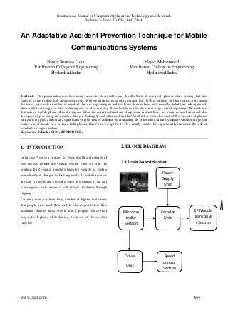
- 1. International Journal of Computer Applications Technology and Research Volume 3– Issue 10, 654 - 660, 2014 An Adaptative Accident Prevention Technique for Mobile Communications Systems Banda Srinivas Goud Vardhaman College of Engineering Hyderabad,India Eliyaz Mahammed Vardhaman College of Engineering Hyderabad,India Abstract: This paper introduces how many times our elders told about the ill-effects of using cell phones while driving, but how many of us have taken their advices seriously. Well we think not even thirty percent. Isn’t it? But whether we like it or not, it is one of the major reasons for number of accident that are happening nowadays. Even doctors have now recently stated that talking on cell phones while driving is as fatal as driving our car after drinking. It can lead to various disastrous major miss-happenings. Do you know that using a mobile phone while driving can affect the cognitive functions of a person, distract his or her visual concentration and also the speed of processing information Are you feeling Scared after reading this? Well it has been also proved that use of cell phones while driving puts a driver at a significantly higher risk of collision by distracting his or her mind. It hardly matters whether the person makes use of hands free or hand-held phones, there’s no escape to it. This deadly combo has significantly increased the risk of accidents in large numbers. Keywords: Vehicle , GSM, RF MODULE. 1. INTRODUCTION In this we Propose a concept for overcome this, it consists of two devices former the vehicle section once we start the ignition the RF signal transfer’s from the vehicle to mobile immediately it changes to Driving mode. If mobile receives the call, it attends and gives the voice information, if the call is emergency only means it will inform the driver through ringing. Certainly there has been large number of figures that shows that people have used their mobile phones just before their accidents. Studies have shown that if people reduce their usage of cell phone while driving, it can cut off the accident rates too. 2. BLOCK DIAGRAM 2.1 Dash Board Section: Power Supply Unit Encoder Unit Microcon troller Section RF Module Transceive r Section Speed control Section Driver Unit www.ijcat.com 654
- 2. International Journal of Computer Applications Technology and Research Volume 3– Issue 10, 654 - 660, 2014 2.2Mobile gadget: RF Module Transceiver Section Decoder Part 3. DESIGN AND IMPLEMENTATION Traditionally, the protection of kindergartens is very relied on the human’s effort and a spotlight like guardians and academics. However, if there's no active informing service give by kindergartens typically, parents haven't any plan of once and whether or not their children safely arrive in their schoolroom when they're picked up by motor coach. each morning the coed attendance offers the primary hand data of kids safety. however generally it's sophisticated to precisely track the attending since the youngsters arrive during a period of your time within the morning and a few of them return with their folks and a few return by motor coach. So we develop an energetic RFID attending system to overcome the barriers and mistakes of manually taking attendance and mix the wireless GSM message service to produce real time responses to their parents’ cellular phone. folks will check the message and understand once their youngsters Power Supply Unit Micro controller Call Indicator Unit Level Converter square measure safely arrived. On the contrary, a noticing message are going to be broadcasted to administrators and oldsters if the youngsters don't show up during a category on time in order that the adults have the enough time to examine out these specific youngsters and stop accident happens. 4. SYSTEM HARDWARE 4.1. ARM Processor: The ARM7 family includes the ARM7TDMI, ARM7TDMI-S, ARM720T, and ARM7EJ-S processors. The ARM7TDMI core is the industry’s most widely used 32-bit embedded RISC microprocessor solution. Optimized for cost and power-sensitive applications, the ARM7TDMI solution provides the low power consumption, small size, and high www.ijcat.com 655
- 3. International Journal of Computer Applications Technology and Research Volume 3– Issue 10, 654 - 660, 2014 performance needed in portable, embedded applications. The ARM7TDMI core uses a three-stage pipeline to increase the flow of instructions to the processor. This allows multiple simultaneous operations to take place and continuous operation of the processing and memory systems. 4.2 Operating modes The ARM7TDMI core has seven modes of operation: User mode is the usual program execution state Interrupt (IRQ) mode is used for general purpose interrupt handling Supervisor mode is a protected mode for the operating system Abort mode is entered after a data or instruction pre fetch abort System mode is a privileged user mode for the operating system Undefined mode is entered when an undefined instruction is executed. The interrupt setting of ARM supports the DHLS to response to the interrupt coming from the server section. 4.3 Interrupt controller The Vectored Interrupt Controller (VIC) accepts all of the interrupt request inputs from the home server section and categorizes them as Fast Interrupt Request (FIQ), vectored Interrupt Request (IRQ), and non-vectored IRQ as defined by programmable settings. So DHLS system can able to separate the command signals and easily will select the priority. The programmable assignment scheme means that priorities of interrupts from the various peripherals can be dynamically assigned and adjusted. Fast interrupt request (FIQ) has the highest priority. If more than one request is assigned to FIQ, the VIC combines the requests to produce the FIQ signal to the ARM processor. The fastest possible FIQ latency is achieved when only one request is classified as FIQ, because then the FIQ service routine does not need to branch into the interrupt service routine but can run from the interrupt vector location. If more than one request is assigned to the FIQ class, the FIQ service routine will read a word from the VIC that identifies which FIQ source(s) is (are) requesting an interrupt. Vectored IRQs have the middle priority. Sixteen of the interrupt requests can be assigned to this category. Any of the interrupt requests can be assigned to any of the 16 vectored IRQ slots, among which slot 0 has the highest priority and slot 15 has the lowest. Non-vectored IRQs have the lowest priority. The VIC combines the requests from all the vectored and non-vectored IRQs to produce the IRQ signal to the ARM processor. The IRQ service routine can start by reading a register from the VIC and jumping there. If any of the vectored IRQs are pending, the VIC provides the address of the highest-priority requesting IRQs service routine, otherwise it provides the address of a default routine that is shared by all the non-vectored IRQs. The default routine can read another VIC register to see what IRQs are active. 4.4 PIC micro controller: The was originally designed around 1980 by General Instrument as a small, fast, inexpensive embedded microcontroller with strong I/O capabilities. PIC stands for "Peripheral Interface Controller". General Instrument recognized the potential for the little PIC and eventually spun off Microchip, headquartered in Chandler, AZ to fabricate and market the PICmicro. The PIC has some advantages in many applications over the older chips such as the Intel 8048/8051/8052 and many others. Its unusual architecture is ideally suited for embedded control. Nearly all instructions execute in the same number of clock cycles, which makes timing control much easier. This is a RISC (Reduced Instruction Set Computer) design, with only thirty-odd instructions to remember; its code is extremely efficient, allowing the PIC to run with typically less program memory than its larger competitors. Very important, though, is the low cost, high available clock speeds, small size, and incredible ease of use of the tiny PIC. For timing-insensitive designs, the oscillator can consist of a cheap RC network. Clock speeds can range from low speed to 20MHz. Versions of the various PIC microcontroller families are available that are equipped with various combinations ROM, EPROM, OTP (One-Time Programmable) EPROM, EEPROM, and FLASH program and data memory. An 18-pin PIC microcontroller typically devotes 13 of those pins to I/O, giving the designer two full 8-bit I/O ports and an interrupt. In many cases, designing with a PIC microcontroller is much simpler and more efficient than using an older, larger embedded microprocessor. www.ijcat.com 656
- 4. International Journal of Computer Applications Technology and Research Volume 3– Issue 10, 654 - 660, 2014 5 ARCHITECTURE OVERVIEW The PIC uses Harvard architecture, unlike the von Neumann architecture used in most general-purpose processors. The von Neumann architecture uses the same bus for program memory, data memory, I/O, registers, etc. This makes it easy to bring the common bus out to device. I/O pins for adding memory, but it limits the bus bandwidth that can be used for any one function since the bus is shared. Von Neumann processors are generally micro coded, CISC (Complex Instruction Set Computer) designs (though there are, of course, exceptions). The Harvard architecture uses separate program memory and data memory busses. This makes it easy to design the processor for very efficient use of program memory, since the program memory bus can be of a much different width than the data memory. Instructions usually (always in the case of the PIC) take up only one program memory location, compared to one, two or even three in a typical von Neumann design. Harvard-architecture machines are generally non-micro coded, RISC (Reduced Instruction Set Computer) designs (again, exceptions are to be found). One drawback to the Harvard architecture is that it is very difficult to bring the memory address and data busses out to device pins, so adding external program memory is difficult at best. For this reason, most Harvard machines have only internal program memory. For example, the popular PIC16F84 contains 1K words of FLASH program memory, 68 bytes of data RAM, and 64 bytes of data EEPROM. While this seems like an extremely limited amount of code and data space, the PIC's incredibly compact code makes the most of it. 1024 instruction word memory actually means 1024 instructions, no less. Even immediate-mode instructions, where an operand is part of the instruction itself, takes only one memory location, as do CALL and GOTO instructions. There even exists a single-chip implementation of a TCP/IP stack and HTTP server written for a 16F84. The PIC is also a non-micro coded design. In larger processors, each binary machine language instruction often is "executed" by a series of microcode steps. While this is a great approach for building large, complex processors with a wide range of instructions, it also leads to great complexity and takes up a lot of real estate. The PIC uses the instruction word itself, decoded by logic gates as it is read from program memory, to control the flow of data through the chip. The seemingly odd 14-bit instruction word length is a direct result of the internal architecture of the processor itself. In the case of the 16F84 or 16C711, we need 13 bits just to address all of program memory. In the case of the smaller 16C54 with only 512 words of program memory and 25 bytes of RAM, we can get by with a 12-bit instruction word -- which is exactly what the 16C54 uses. Conversely, with more memory we would use a longer instruction word, like the 16 bits in the 18Cxxx family. 6 DRIVER UNIT A relay is an electrically operated switch. Current flowing through the coil of the relay creates a magnetic field which attracts a lever and changes the switch contacts. The coil current can be on or off so relays have two switch positions and they are double throw (changeover) switches. Relays allow one circuit to switch a second circuit which can be completely separate from the first. For example a low voltage battery circuit can use a relay to switch a 230V AC mains circuit. There is no electrical connection inside the relay between the two circuits, the link is magnetic and mechanical. Relays are very simple devices. There are four major parts in every really. They are Electromagnet Armature that can be attracted by the electromagnet Spring Set of electrical contacts 7 WORKING When a current flows through the coil, the resulting magnetic field attracts an armature that is mechanically linked to a moving contact. The movement either makes or breaks a connection with a fixed contact. When the current to the coil is switched off, the armature is returned by a force approximately half as strong as the magnetic force to its relaxed position. Usually this is a spring, but gravity is also used commonly in industrial motor starters. Most relays are manufactured to operate quickly. In a low voltage application, this is to reduce noise. In a high voltage or high current application, this is to reduce arcing. www.ijcat.com 657
- 5. International Journal of Computer Applications Technology and Research Volume 3– Issue 10, 654 - 660, 2014 Fig 8.1 Circuit symbol of a relay The relay's switch connections are usually labelled COM, NC and NO: COM = Common, always connect to this, it is the moving part of the switch. NC = Normally Closed, COM is connected to this when the relay coil is off. NO = Normally Open, COM is connected to this when the relay coil is on. NOTE: Connect to COM and NO if you want the switched circuit to be on when the relay coil is on. Connect to COM and NC if you want the switched circuit to be on when the relay coil is off. 7.1 Advantages of relays: Like relays, transistors can be used as an electrically operated switch. For switching small DC currents (< 1A) at low voltage they are usually a better choice than a relay. However transistors cannot switch AC or high voltages (such as mains electricity) and they are not usually a good choice for switching large currents (> 5A). In these cases a relay will be needed. Advantages of relays compared to other switching devices are: The complete electrical isolation improves safety by ensuring that high voltages and currents cannot appear where they should not be. Relays can switch many contacts at once. Relays come in all shapes and sizes for different applications and they have various switch contact configurations. Double Pole Double Throw (DPDT) relays are common and even 4-pole types are available. You can therefore control several circuits with one relay or use one relay to control the direction of a motor. Relays can switch AC and DC, transistors can only switch DC. Relays can switch high voltages, transistors cannot. 8 GSM MODEM: 8.1 Definitions: Global system for mobile communication (GSM) is a globally accepted standard for digital cellular communication. GSM is the name of a standardization group established in 1982 to create a common European mobile telephone standard that would formulate specifications for a pan-European mobile cellular radio system operating at 900 MHz’s 8.2 The GSM network: GSM provides recommendations, not requirements. The GSM specifications define the functions and interface requirements in detail but do not address the hardware. The reason for this is to limit the designers as little as possible but still to make it possible for the operators to buy equipment from different suppliers. The GSM network is divided into three major systems: the switching system (SS), the base station system (BSS), and the operation and support system (OSS). The basic GSM network elements are shown in below figure GSM Network Elements 8.3 GSM modem: A GSM modem is a wireless modem that works with a GSM wireless network. A wireless modem behaves like a dial-up modem. The main difference between them is that a dial-up modem sends and receives data through a fixed telephone line while a wireless modem sends and receives data through radio waves. 8.4 RF communication: www.ijcat.com 658
- 6. International Journal of Computer Applications Technology and Research Volume 3– Issue 10, 654 - 660, 2014 Radio Frequency, any frequency within the electromagnetic spectrum associated with radio wave propagation. When an RF current is supplied to an antenna, an electromagnetic field is created that then is able to propagate through space. Many wireless technologies are based on RF field propagation. Radio Frequency: The 10 kHz to 300 GHz frequency range that can be used for wireless communication. Also used generally to refer to the radio signal generated by the system transmitter, or to energy present from other sources that may be picked up by a wireless receiver. Wireless mouse, keyboard Wireless data communication Alarm and security systems Home Automation, Remote control Automotive Telemetry Intelligent sports equipment Handheld terminals, Data loggers Industrial telemetry and tele-communications In-building environmental monitoring and control High-end security and fire alarms 8.5 Transmitter: The TWS-434 extremely small, and are excellent for applications requiring short-range RF remote controls. The transmitter module is only 1/3 the size of a standard postage stamp, and can easily be placed inside a small plastic enclosure. TWS-434: The transmitter output is up to 8mW at 433.92MHz with a range of approximately 400 foot (open area) outdoors. Indoors, the range is approximately 200 foot, and will go through most walls. Figure – 7.1.2 The TWS-434 transmitter accepts both linear and digital inputs can operate from 1.5 to 12 Volts-DC, and makes building a miniature hand-held RF transmitter very easy. The TWS-434 is approximately 1/3 the size of a standard postage stamp. 9 CONCLUSION This deadly combo has significantly increased the risk of accidents in large numbers. Certainly there has been large number of figures that shows that people have used their mobile phones just before their accidents. Studies have shown that if people reduce their usage of cell phone while driving, it can cut off the accident rates too. So next time if your cell rings, make sure to answer your phone call only after when you reach your destination and not in-between the way. 10 REFERENCES: [1]. A. X. Liu and L. A. Bailey, "PAP: A privacy and authentication protocol for passive RFID tags," Comput. Commun., vol. 32, pp. 1194-1199, 2009. [2] .J. A. Wolff, "RFID tags – an intelligent bar code replacement," IBM Corporation, 2001. [3]. R. Weinstein, "RFID: a technical overview and its application to the enterprise," IT Professional, vol. 7, pp. 27 - 33, May-June 2005 [4] .A. Juels, "RFID Security and Privacy: A Reasearch Survey," RSA Laboratories, 28 September 2005. [5]. G. Venkataramani and S. Gopalan, "Mobile phone based RFID architecture for secure electronic Payments using RFID credit cards," Availability, Reliability and Security, 2007. www.ijcat.com 659
- 7. International Journal of Computer Applications Technology and Research Volume 3– Issue 10, 654 - 660, 2014 ARES 2007. The Second International Conference on, pp. 610-620, 10-13 April 2007. [6]..Mikko Lehtonen, Thorsten Staake, Florian Michahelles, and E. Fleisch, "From Identification to Authentication–A Review of RFID Product Authentication Techniques," Printed handout of Workshop on RFID Security-RFIDSec, Springer, 2006. [7]. N. W. Lo and K.-H. Yeh, "Novel RFID Authentication Schemes for Security Enhancement and System Efficiency," Lecture Notes in Computer Science, Secure Data Management, vol. 4721/2007, pp. 203-212, 2007. www.ijcat.com 660