
Recomendados
Más contenido relacionado
La actualidad más candente
La actualidad más candente (20)
Similar a Gearless transmission
Similar a Gearless transmission (20)
Último
Último (20)
Gearless transmission
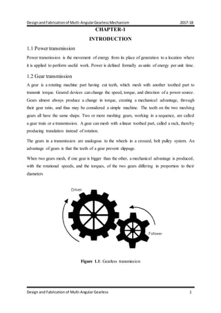
- 1. DesignandFabricationof Multi-AngularGearlessMechanism 2017-18 Design and Fabrication of Multi-Angular Gearless 1 CHAPTER-1 INTRODUCTION 1.1 Power transmission Power transmission is the movement of energy from its place of generation to a location where it is applied to perform useful work. Power is defined formally as units of energy per unit time. 1.2 Gear transmission A gear is a rotating machine part having cut teeth, which mesh with another toothed part to transmit torque. Geared devices can change the speed, torque, and direction of a power source. Gears almost always produce a change in torque, creating a mechanical advantage, through their gear ratio, and thus may be considered a simple machine. The teeth on the two meshing gears all have the same shape. Two or more meshing gears, working in a sequence, are called a gear train or a transmission. A gear can mesh with a linear toothed part, called a rack, thereby producing translation instead of rotation. The gears in a transmission are analogous to the wheels in a crossed, belt pulley system. An advantage of gears is that the teeth of a gear prevent slippage. When two gears mesh, if one gear is bigger than the other, a mechanical advantage is produced, with the rotational speeds, and the torques, of the two gears differing in proportion to their diameters Figure 1.1: Gearless transmission
- 2. DesignandFabricationof Multi-AngularGearlessMechanism 2017-18 Departmentof Mechanical Engineering,S.I.T,Tumakuru 2 1.3 Advantages: 1. The use of peripheral speed and power range. 2. High efficiency. 3. Transmission ratio stability. 4. Long life. 5. High reliability. 6. Can achieve parallel axis, arbitrary angle intersecting axis and arbitrary Angular cross shaft drive between. 1.4 Disadvantages: 1. Require a higher manufacturing and installation accuracy. 2. High cost. 3. Not suitable for long-distance drive between the two shafts. 1.5 What is gearless transmission? It is an ingenious link mechanism of slider and kinematic chain principle. Transmits power at any angle without utilising gears Transmits the power between two shafts whose axes are at 90 degrees through bent links. Three links slide relatively according to the motion given to input shaft. Due to this, the rotational motion of input shaft is converted into sliding motion of links which is then converted to rotational motion of the output shaft Figure 1.2: Gearless transmission
- 3. DesignandFabricationof Multi-AngularGearlessMechanism 2017-18 Departmentof Mechanical Engineering,S.I.T,Tumakuru 3 TABLE 1.1: Advantages of gearless over geared mechanism GEARLESS GEARED Manufacturing methods- Less costly. No need of special machines Less calculations Manufacturing methods- Costly. Manufactured on special purpose machines Complex calculations Cause of failure- Pitting, corrosion, erosion and fatigue effect less severely Replacement of defected pin only Cause of failure- Pitting, corrosion, erosion and fatigue have severe effect. Replacement of entire gear set needs to be done. Lubrication and cooling Simple Easy to cool Lubrication and cooling- Complex system Cooling is a big issue Torque transmitting capacity Used in low torque applications Torque transmitting capacity High torque applications Different speed at any angle is easily done Different speed at any angle is not easily possible 1.6 Disadvantages of gearless mechanism Does not work at very low starting torque. Improper hole drilling could pose much problem. Sudden load would cause mechanism breakdown. Links are to be replaced after certain cycle time. Speed ratio is always constant 1:1.
- 4. DesignandFabricationof Multi-AngularGearlessMechanism 2017-18 Departmentof Mechanical Engineering,S.I.T,Tumakuru 4 1.7 Multi -angular gearless mechanism Multi-Angular Gearless Drive is a motion transmitting device used for transmitting motion at multiple angles between the driving and the driven shaft. The scrutiny of this mechanism would reveal that it comprises of pins ranging from 3 to 8 pins per assembly and with increase in the number of pins operation becomes smoother. These pins slide inside symmetrically spaced holes machined on solid cylindrical disc. Thus, the sliding pairs help the shaft to revolve at various angles. Figure 1.3: Multi-Angular Gearless Transmission 1.8 Advantages of multi-angular mechanism High efficiency between input and output power shafts. It is very smooth acting device and power loss is minimum. It can be run at any speed even at very high speed and is very quiet Very little friction. 1.9 Applications of multi-angular gearless transmission Tower clocks Gang drilling (Multi-spindle drilling) Lubrication pump for CNC lathe Angular drilling between 0- 90 degree Movement of periscope in submarines
- 5. DesignandFabricationof Multi-AngularGearlessMechanism 2017-18 Departmentof Mechanical Engineering,S.I.T,Tumakuru 5 CHAPTER-2 OBJECTIVE To understand and implementation of multi-angular mechanism. The transmission of power from one shaft to another shaft. Flexible to transfer power from 0 to 90 degrees in without the usage of gears. Extensive literature survey. Modelling of mechanism with different number of pins Calculating the different size of equipment depending on requirement Fabrication of mechanism
- 6. DesignandFabricationof Multi-AngularGearlessMechanism 2017-18 Departmentof Mechanical Engineering,S.I.T,Tumakuru 6 CHAPTER-3 LITERATURE SURVEY R. Somaraj, et. al, Power transmission for skew shafts with the help of number of pins or links must be odd 3,5,7, 9... pins or links are fixed in the drilled holes at the both shaft ends due to which motion is transferred. The work king of this arrangement is very smooth and work effectively with a very minimum amount of power losses, Which is skilful and is having something precise in transmitting power at right angle without any gears being manufactured. [1] Shiv Pratap Singh Yadav,et.al, The Elbow Mechanism is the mechanism which is used to transmit power though strong shafts which are bend at 90°.In this the power is given to the outer plate and the outer plate rotates through which the L – shaped shafts and through which the power is transmitted to other plate which is present at an angle of 90°.Hence very little friction plays while the power is being transmitted.[2] Multi-angular gearless mechanism: The multi-angular gearless mechanism is the mechanism which is used to transmit power though strong shafts which are bend flexible to transmit power 0 to 90 degree. In this the power is given to the outer plate and the outer plate rotates through 90 degrees which the shafts and through which the power is transmitted to other plate which is present at an angle of 0 to 90 degrees. Hence very little friction plays while the power is being transmitted.
- 7. DesignandFabricationof Multi-AngularGearlessMechanism 2017-18 Departmentof Mechanical Engineering,S.I.T,Tumakuru 7 CHAPTER-4 METHODOLOGY Figure 4.1: Flow chart of methodology Study of research papers Study of mechanism Selection of material Design of parts ModellingSimulation Fabrication and assembly Comparison
- 8. DesignandFabricationof Multi-AngularGearlessMechanism 2017-18 Departmentof Mechanical Engineering,S.I.T,Tumakuru 8 4.1 Materials and cost Table 4.1: Materials used and cost SL.NO PART NAME MATERIAL QUANTITY TOTAL COST 1 DISC MILD STEEL 2 700rs 2 BEARINGS CAST IRON 2 1000rs 3 SHAFTS MILD STEEL 2 800rs 4 LINKS CAST STEEL 6 1200rs 5 FRAME MILD STEEL 1 2000rs
- 9. DesignandFabricationof Multi-AngularGearlessMechanism 2017-18 Departmentof Mechanical Engineering,S.I.T,Tumakuru 9 4.2 Designof 3D model and different views of projection Figure 4.2: Front View Figure 4.3: Right View Scale 1:2.5 Scale 1:2.5 Figure 4.4:Top view Figure 4.5:Iso-metric view Scale 1:2.5 Scale 1:2.5 All dimensions are in mm
- 10. DesignandFabricationof Multi-AngularGearlessMechanism 2017-18 Departmentof Mechanical Engineering,S.I.T,Tumakuru 10 4.3 General Procedure in Machine Design The general steps to be followed in designing the machine are as followed. Preparation of a statement of the problem indicating the purpose of the machine. Selection of groups of mechanism for the desire motion. Calculation of the force and energy on each machine member. Selection of material. Determining the size of component drawing and sending for manufacture. Preparation of component drawing and sending for manufacture. Manufacturing and assembling the machine. 4.4 DesignCalculations Designof Shaft: Considering 25% of overload, Tmax = 4947 N-mm T= 16 ×τ×dᵌ [Shear stress, τ= 2 40N mm d= 8.57 P.S.G. Design data book] d= 9 mm Taking, FOS= 2 d= d×2 d= 18 mm Designof Hub: Diameter of Hub, D= 2d+13 [P.S.G. Design data book] D= 49 Adopt, D= 50 mm Force acting on the Hub, F= T/r F= 197.88 N Designof Links: Torque on each shaft, 3 T = 1649 n-mm T = 16 ×τ×dᵌ = 5.943 d= 6 mm
- 11. DesignandFabricationof Multi-AngularGearlessMechanism 2017-18 Departmentof Mechanical Engineering,S.I.T,Tumakuru 11 4.5 WORKING Here is a wonderful mechanism that carries force through a 180-degree slot bend. Translating rotational motion around an axis usually involves gears, which can quickly become complicated, inflexible and clumsy-looking, often ugly. So, instead of using gears, this technology elegantly converts rotational motion using a set of cylindrical bars, bent to 90º, in a clever, simple and smooth process that translates strong rotational force even in restricted spaces. Although this illustration shows a right angle transmission this drive can be applied also to shafts located at intermediate angle between zero degree to ninety degree. In making this transmission, it is essential to have the holes for a given rod located accurately in the same holes must be equally spaced in radial and circumferential directions, be parallel to each rod should be bent to at angle at which the shaft are to be located. A gearless transmission is provided for transmitting rotational velocity from an input connected to three bent links. Both the input shaft and the housing have rotational axes. The rotational axis of the input shaft is disposed at an angle of 180 degree with respect to the rotational axis of the housing. As a result, rotation of the input shaft results in a processional motion of the axis of the bent link. The rotary and reciprocating motion of bent link transmit rotation of prime mover to flexible degree without any gear system to an output shaft without gears. The transmission includes an input shaft. Motion is transmitted from driving to the driven shaft through the sliding pairs which remain either straight or bent using universal joints, as per requirement between the shafts. These sliding pairs are placed in equally spaced holes around a solid cylindrical disc, which allow it to move freely. Thus, when the torque is applied at the input shaft, a uniform torque is generated at the output. Depending on the precision with which the gearless drive has been designed and the limitation of the universal joint, the angular range within which the Multi- Angular Gearless drive would operate smoothly is decided. This type of drive is especially suitable where quite operation at high speed and at various angles is required. Also, this type of gearless drive has low vibrations as compare to other motion transmission systems like simple universal joint which makes it preferable.
- 12. DesignandFabricationof Multi-AngularGearlessMechanism 2017-18 Departmentof Mechanical Engineering,S.I.T,Tumakuru 12 4.5.1 Fabrication It consists of links or rods that flexible to rotate 0 to 90 degrees. The number of links required would be 3 to 8. The more the links, the smoother will be the operation. Links are made up of bright bars as the bright bar material has good surface finish. These links slides inside the through and through drilled cylinder. Thus, forming a sliding pair. These cylinders are coupled to the input and output shaft with help of key. 4.5.2 Fabricated model Figure 4.6: Fabricated model
- 13. DesignandFabricationof Multi-AngularGearlessMechanism 2017-18 Departmentof Mechanical Engineering,S.I.T,Tumakuru 13 4.6 FABRICATION PROCESS 4.6.1MEASURING AND MARKING Figure 4.7: Measuring and marking After getting the material, the next step is measurement and marking material The equipment used in this process is measuring tape or steel rule and scriber all the components are marked as per required dimensions. 4.6.2 CUTTING MATERIAL After the measurement and marking process, introduce the process cutting the material using cutting machine. On the cutting machine, we cut the materials for making the desired shape and sizes of L- angular, fixed plate. Figure 4.8: Cutting Machine On the cutting machine, we cut the materials for making the desired shape and sizes of L- angular, fixed plate.
- 14. DesignandFabricationof Multi-AngularGearlessMechanism 2017-18 Departmentof Mechanical Engineering,S.I.T,Tumakuru 14 4.6.3 GRINDING Figure 4.9: Bench Grinder Grinding is an abrasive machining process that uses a grinding wheel as the cutting tool. A wide variety of machines are used for grinding: 1. Hand-cranked knife-sharpening stones (grindstones). 2. Handheld power tools such as angle grinders and die grinders. 3. Various kinds of expensive industrial machine tools called grinding machines. 4. Bench grinders often found in residential garages and basements. Grinding practice is a large and diverse area of manufacturing and tool making. It can produce very fine finishes and very accurate dimensions; yet in mass production contexts it can also rough out large volumes of metal quite rapidly. It is usually better suited to the machining of very hard materials than is "regular" machining (that is, cutting larger chips with cutting tools such as tool bits or milling cutters), and until recent decades it was the only practical way to machine such materials as hardened steels. Compared to "regular" machining, it is usually better suited to taking very shallow cuts, such as reducing a shaft’s diameter by half a thousandth of an inch or 12.7 um. Grinding is a subset of cutting, as grinding is a true metal- cutting process. Each grain of abrasive functions as a microscopic single-point cutting edge (although of high negative rake angle), and shears a tiny chip that is analogous to what would conventionally be called a "cut" chip (turning, milling, drilling, tapping, etc.). Similar abrasive cutting processes are lapping and sanding.
- 15. DesignandFabricationof Multi-AngularGearlessMechanism 2017-18 Departmentof Mechanical Engineering,S.I.T,Tumakuru 15 4.6.4 DRILLING Drilling is the most common machining process whereby the operation involves making round holes in metallic and nonmetallic materials. Figure 4.10: Drilling process After cutting the material, it is need to make holes for the parts like wooden sheet, clamps, frame, by different drill bits. So, mark the position to drill using steel rule and scriber and then punch a small hole by using center punch before start drill. After that, start the drilling. Drilling is a cutting process that uses a drill bit to cut or enlarge a hole of circular cross-section in solid materials. The drill bit is a rotary cutting tool, often multipoint. The bit is pressed against the work piece and rotated at rates from hundreds to thousands of revolutions per minute. This forces the cutting edge against the work piece, cutting off chips from what will become the hole being drilled. Exceptionally, specially-shaped bits can cut holes of non-circular cross section. Drilled holes are characterized by their sharp edge on the entrance side and the presence of burrs on the exit side (unless they have been removed). Also, the inside of the hole usually has helical feed marks. Drilling may affect the mechanical properties of the work piece by creating low residual stresses around the hole opening and a very thin layer of highly stressed and disturbed material on the newly formed surface. This causes the work piece to become more susceptible to corrosion at the stressed surface. A finish operation may be done to avoid the corrosion. Zinc plating or any other standard finish operation of 14 to 20 µm can be done which helps to avoid any sort of corrosion. When possible, drilled holes should be located perpendicular to the work
- 16. DesignandFabricationof Multi-AngularGearlessMechanism 2017-18 Departmentof Mechanical Engineering,S.I.T,Tumakuru 16 piece surface. This minimizes the drill bit's tendency to "walk", that is, to be deflected, which causes the hole to be misplaced. The higher the length-to-diameter ratio of the drill bit, the higher the tendency to walk. 4.6.5 WELDING Arc welding is a type of welding that uses a welding power supply to create an electric arc between an electrode and the base material to melt the metals at the welding point. By using this we make the frame and the handle. Welding is the process of joining similar metals by the application of heat, with or without application of pressure or filler metal, in such a way that the joint is equivalent in composition and characteristics of the metals joined. In the beginning, welding was mainly used for repairing all kinds of worn or damaged parts. Now, it is extensively used in manufacturing industry, construction industry (construction of ships, tanks, locomotives and automobiles) and maintenance work, replacing riveting and bolting, to a greater extent. Figure 4.11: Welding process
- 17. DesignandFabricationof Multi-AngularGearlessMechanism 2017-18 Departmentof Mechanical Engineering,S.I.T,Tumakuru 17 CHAPTER-5 CONCLUSION The gearless power transmission is one of the budding ideas of the technology. It has a high scope in future to replace the usage of bevel gears which will be replaced. It is being concluded from the fabrication that the mechanism with 6 links made up of mild steel material is works perfectly. Also concluded that as the number of links increases smoother the operation.
- 18. DesignandFabricationof Multi-AngularGearlessMechanism 2017-18 Departmentof Mechanical Engineering,S.I.T,Tumakuru 18 CHAPTER-6 REFERENCES [1] Ashish Kumar, Puwar, Sagar Rana, Shishir Bist “Multi-Angular Gearless Drive” International Journal of Scientific and Engineering Research, Volume 6, Issue 7, July- 2015 . [2] R. Somaraj, B. Sailesh “Design and Fabrication of Gearless Power Transmission for Skew Shafts” International Research Journal of Engineering and Technology (IRJET), Volume:04, Issue:04, April-2017 (pg.no:1018-1023). [3] Jagushte G.S, Kudalkar Hrishikesh, Patil Vikas, Vishal “Design, Analysis and Fabrication of Gearless Transmission by Elbow Mechanism” IJSRD-International Journal for Scientific Research and Development, Volume 4, Issue 02, 2016.