Pressure regulator valves for industrial process control
•
0 likes•1,490 views

Cash Valve provides highly engineered pressure regulating and back pressure valves along with cost effective custom packages for OEM engineered applications for industrial and commercial customers who require mechanical control of pressure. Cash Valve provides product from cryogenic through high temperature for Steam, Air, Gas, and Liquid applications meeting tight shut-off and extended service life. Cash Valve provides code certifications that meet various global standards such as PED, TPED, and Chinese as well as non-code requirements.
![2
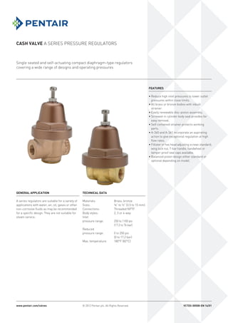
Cash Valve A Series pressure regulators
Operation
All A series pressure regulators are supplied with the requested delivery pressure pre-adjusted at
the factory. Pressure adjustment is accomplished by turning the adjusting screw either clockwise
to increase delivery pressure or counter-clockwise to reduce delivery pressure. For example,
turning the adjusting screw clockwise forces the adjusting spring to act against the diaphragm
assembly and move the internal valve seat to the open position.
When high inlet pressure is applied, it flows into the regulator, through the open seat, up under
the diaphragm and on through the outlet. As the outlet pressure builds up under the diaphragm to
the adjusted psi setting, the downward adjusting spring pressure is overcome and the regulating
valve seat closes to maintain the required delivery pressure.
Models overview
A-16
• Sizes: ¼” or ⅜” (7 or 10.5 mm)
• Body styles:
- Two-way valve with one female inlet and opposite female outlet.
- Three-way valve with one female inlet and opposite female outlet plus a left-hand side ¼” (7 mm)
NPTF gauge connection[1]
.
A-31 and A-31S
• Sizes: ⅛, ¼” and ⅜ (3.5, 7 and 10.5 mm)
• Body styles:
- Type A-31: two-way valve with one female inlet and opposite female outlet.
- Type A-31S: three-way valve with one female inlet and opposite female outlet plus either a left or
right-hand side ¼” (7 mm) NPTF gauge connection[1]
.
A-360 through A-365
• Sizes: ¼”, ⅜” and ½” (7, 10.5 and 15 mm)
• Body styles:
- Type A-360 and A-365 - two-way valve with one female inlet and opposite female outlet.
- Type A-361 - adaptable for three-way or four-way use.
Note
1. Gauge connection designation is in relation to main valve inlet with valve in upright position.
Type A-16 (two-way).
Type A-360, 365
Type A-361
Type A-31](data:image/gif;base64,R0lGODlhAQABAIAAAAAAAP///yH5BAEAAAAALAAAAAABAAEAAAIBRAA7)
Recommended
Recommended
More Related Content
What's hot
What's hot (20)
Viewers also liked
Viewers also liked (20)
Similar to Pressure regulator valves for industrial process control
Similar to Pressure regulator valves for industrial process control (20)
More from Mountain States Engineering and Controls
More from Mountain States Engineering and Controls (20)
Recently uploaded
Recently uploaded (20)
Pressure regulator valves for industrial process control
- 1. Cash Valve A Series pressure regulators © 2012 Pentair plc. All Rights Reserved. Single seated and self-actuating compact diaphragm-type regulators covering a wide range of designs and operating pressures Features • Reduce high inlet pressures to lower outlet pressures within close limits. • All brass or bronze bodies with inbuilt strainer. • Easily renewable disc-piston assembly. • Screwed-in cylinder body seat provides for easy removal. • Self contained strainer protects working parts. • A-360 and A-361 incorporate an aspirating action to give exceptional regulation at high flow rates. • Fillister or hex head adjusting screws standard; wing lock nut, T-bar handle, handwheel or tamper-proof seal caps available. • Balanced piston design either standard or optional depending on model. General application A series regulators are suitable for a variety of applications with water, air, oil, gases or other non-corrosive fluids as may be recommended for a specific design. They are not suitable for steam service. Technical data Materials: Brass, bronze Sizes: ⅛” to ½” (3.5 to 15 mm) Connections: Threaded NPTF Body styles: 2, 3 or 4-way Inlet pressure range: 250 to 1100 psi (17.2 to 76 bar) Reduced pressure range: 0 to 250 psi (0 to 17.2 bar) Max. temperature: 180°F (82°C) www.pentair.com/valves VCTDS-00508-EN 16/01
- 2. 2 Cash Valve A Series pressure regulators Operation All A series pressure regulators are supplied with the requested delivery pressure pre-adjusted at the factory. Pressure adjustment is accomplished by turning the adjusting screw either clockwise to increase delivery pressure or counter-clockwise to reduce delivery pressure. For example, turning the adjusting screw clockwise forces the adjusting spring to act against the diaphragm assembly and move the internal valve seat to the open position. When high inlet pressure is applied, it flows into the regulator, through the open seat, up under the diaphragm and on through the outlet. As the outlet pressure builds up under the diaphragm to the adjusted psi setting, the downward adjusting spring pressure is overcome and the regulating valve seat closes to maintain the required delivery pressure. Models overview A-16 • Sizes: ¼” or ⅜” (7 or 10.5 mm) • Body styles: - Two-way valve with one female inlet and opposite female outlet. - Three-way valve with one female inlet and opposite female outlet plus a left-hand side ¼” (7 mm) NPTF gauge connection[1] . A-31 and A-31S • Sizes: ⅛, ¼” and ⅜ (3.5, 7 and 10.5 mm) • Body styles: - Type A-31: two-way valve with one female inlet and opposite female outlet. - Type A-31S: three-way valve with one female inlet and opposite female outlet plus either a left or right-hand side ¼” (7 mm) NPTF gauge connection[1] . A-360 through A-365 • Sizes: ¼”, ⅜” and ½” (7, 10.5 and 15 mm) • Body styles: - Type A-360 and A-365 - two-way valve with one female inlet and opposite female outlet. - Type A-361 - adaptable for three-way or four-way use. Note 1. Gauge connection designation is in relation to main valve inlet with valve in upright position. Type A-16 (two-way). Type A-360, 365 Type A-361 Type A-31
- 3. 3 B C A A-16 X X X X 250 2-180 180 2-30 10-50 25-90 80-120 100-180 A-16 Moderate regulation low to medium capacity Application Type A-16 regulators are suitable for air, water, oil, fluids, and gas applications and are intended for use on equipment requiring moderate regulation, low to medium capacity and installations where space limitations and flexibility of hook-up are important factors. They are designed for initial pressures up to 250 psi (17.2 bar) and delivery pressures ranging from 2 to 180 psi (0.14 to 12.4 bar) depending on the spring used. The maximum operation temperature is 180°F (82°C). The A-16 type regulator is suitable for use in drinking fountains, bubblers, water coolers, humidifiers, beverage dispensers, spray paint rigs, air tools, etc. Type A-16 (two-way) interiorBody styles Style 1 (two-way) Style 2 (three-way) Inlet Inlet Outlet Outlet Outlet (Gauge conn.) Specifications Type Description Maximum inlet pressure psi Adjustable range psi Maximum operating temperature °F Size Body style ¼” ⅜” Two-way Three-way Cash Valve A Series pressure regulators A-16 Moderate regulation low to medium capacity Materials of construction Part description Materials Body Brass Spring chamber Aluminum Spring button Brass Adjusting spring Steel Diaphragm gasket Brass Diaphragm NBR Pressure plate Brass Pusher post button Brass Cylinder Brass Piston Brass Seat disc NBR Piston spring 302 stainless steel Strainer screen Brass Specifications Dimensions Description A B C Size Style Ship. wt. (lbs) 2¼” 3½” 13/16” ¼” or ⅜” 2-way, 3-way 1¾ Spring range of adjustment (in psi) Type A-16 (two-way)
- 4. 4 25 15 1.2 1.5 2.0 8 13 17 50 40 1.2 1.5 2.0 8 13 17 25 1.4 2.2 2.5 11 21 25 75 50 2.7 3.0 5.5 20 25 45 25 3.0 3.5 3.5 14 27 32 100 75 2.8 3.0 5.7 28 25 48 50 3.0 3.6 9.0 25 30 60 25 3.0 3.6 3.5 25 35 41 125 100 2.8 3.0 5.7 28 25 45 75 3.7 4.0 7.0 34 35 62 50 3.2 4.0 5.2 34 40 78 150 100 3.7 4.0 7.0 34 35 62 75 3.7 4.5 8.5 34 40 78 50 3.2 4.8 10.5 27 45 95 25 1.8 4.8 10.5 27 45 95 200 150 4.4 4.4 7.5 47 45 85 100 4.2 4.5 10.0 38 45 95 75 4.2 5.0 13.5 38 45 95 50 4.2 5.0 13.5 38 45 95 300 150 4.7 5.0 13.5 54 45 110 100 4.7 5.0 13.5 54 45 95 50 4.7 5.0 13.5 54 45 95 Cash Valve A Series pressure regulators Capacity Information Inlet - psig Outlet - psig Water (GPM) Air (SCFM) A-31/A-16 ¼” A-360 ½” A-360 A-31/A-16 ¼” A-360 ½” A-360 Notes 1. The capacity information in this table is for general application use representing average conditions. Where capacities and sizing are critical, consult your sales representative. 2. Types A-31 and A-16 provide the same capacity. 3. Capacity for ¼ and ⅜ A-360 same for A-361 and A-365. 4. Capacity for ½ A-360 same as A-361. 5. Capacities are based upon a 20% falloff.
- 5. 5 Cash Valve A Series pressure regulators Types A-31, A-31S: compact and economical regulators Application Types A-31 and A-31S pressure regulating valves are designed for installations in systems with initial pressures up to 300 psi (20.7 bar) and where space and cost limitations are important. The standard adjustment range is from 2 to 180 psi (0.14 to 12.4 bar) and the maximum operating temperature is 180°F (82°C). For higher temperature installations consult your sales representative. These regulators are for use on water and air, suitable for drinking fountains, bubblers, water coolers, humidifiers, beer pumps, beverage dispensers, spray paint outfits, air tools, etc. They are also suitable for other liquids and gases if recommended by the factory; for specific advice, please write giving full details of your requirements. Sizes Types A-31 and A-31S are available in ⅛”, ¼” and ⅜ (3.5, 7 and 10.5 mm) sizes and in various optional body styles. Body styles Type A-31: Two-way valve with one female inlet and opposite female outlet. Type A-31S: Three-way valve with one female inlet and opposite female outlet plus either a left or right-hand side ¼” (7 mm) NPTF gauge connection. Specify gauge connection required when ordering. Note Gauge connection designations are in relation to main valve inlet with valve in the upright position. Optional balanced piston The Type A-31 regulator can be furnished with a balanced piston construction for a small extra charge. This design is particularly effective in keeping the delivery pressure near constant when there are wide fluctuations in the inlet pressure. Pressure adjusting screws Type A-31 and A-31S pressure regulators are fitted with a Fillister head adjusting screw and hex lock nut as standard. They can also be supplied with either a T-handle or black plastic handwheel with wing lock nut arrangement at a small extra charge. The handwheels are particularly suited for panel mounted installations both for improved appearance as well as ease of making pressure adjustments. Mounting accessories These regulators can be equipped with a special bushing and nut for panel mounting. Special designs Various modifications of the Type A-31 pressure regulating valve are available to meet specific applications. Pressure adjusting screws Mounting accessories Type A-31 (with bushing for panel mounting, T-handle, or with handwheel) Standard adjusting screw T-Handle Handwheel Type A-31
- 6. 6 C B A A-31 X X X X 300 2-180 ❖ 180 A-31S X X X X 300 2-180 ❖ 180 2-15 2-30 10-50 30-90 80-120 100-180 Cash Valve A Series pressure regulators A-31, A-31S Compact and economical regulators Specifications Description Maximum inlet pressure (psi) Adjustable range (psi) Balanced piston design Maximum operating temperature (°F) Size Body style Type ⅛” ¼” ⅜” Two-way Three-way Note ❖ Optional Materials of construction Part description Materials Body Brass Spring chamber Brass or aluminum Spring button Brass Adjusting spring Steel or stainless steel Diaphragm gasket Brass Diaphragm NBR Pressure plate Brass Piston Brass Seat disc NBR Piston spring 302 stainless steel Specifications Dimensions Type A B C ⅛, ¼ ⅜ Ship. wt. (lbs) 2¼” 33/16” ¼” A31, A31S 1¼ 2¼” 33/16” ⅝” A31 balanced piston 1⅜ Spring range of adjustment (in psi) Type A-31 Note Additional spring ranges are available, see page 7.
- 7. 7 Cash Valve A Series pressure regulators A16, A31, A31S, A31VR, A32, A32S Selection guide Example: A16 A W S A S B B F 02 - D 0005 Model A16 A16 A31 A31 A31S A31S A31V A31VR A32Z A32 w/bronze body A32E A32 w/stainless steel body A32S A32S Size Y ⅛ (A31, A31S) A ¼ (A16, A31, A31S, A31VR, A32, A32S) B ⅜ (A16, A31, A31S, A32) Service W Water/air C Cryogenic (A32Z, A32E) F Final line gas (A31) V Vacuum service (A32VR) Body/connection style S Side inlet/side outlet - straight thru (A16, A31, A32) R Side inlet/side outlet - straight thru w/right side gauge port (A31S) L Side inlet/side outlet - straight thru w/left side gauge port (A16, A31S) B Side inlet/bottom outlet w/straight thru gauge connection (A31VR) Spring chamber material A Aluminum spring chamber (A16, A31, A31S, A32, A32S) Z Brass spring chamber (A31, A32, A31VR only) C Brass chrome plate spring chamber (A32 only) Spring chamber style S Standard P Panel mount N Non-vented Diaphragm material B NBR (A16, A31, A31S, A32S) T Neoprene w/PTFE liner (A31, A31S) L NBR w/ PTFE liner (A31, A31S) Z Bronze (A32 only) G 316 SST (A32) R EPR (A31VR, A32S) N Neoprene (A31, A31S) F EPR w/ PTFE liner (A31VR) Seat material B NBR (A16, A31, A31S, A32S) S Silicone (A31VR) T PTFE (A31, A32, A32S) K Kalrez (A31VR) V FKM (A31, A31S) Pressure screw style F Fillister (A16, A31, A31S, A32, A32S) K Knurled (A31VR) T T-handle (A31, A31S) W Handwheel plastic (A31) H Hex (A31, A31S, A32) Variation 01 Standard 11 Standard variation w/inlet screen (A31, A32) 02 Balanced piston (A31, A31S) 12 Balanced piston w/inlet screen (A31) Design revision (-) Original design Spring material D Carbon steel (Industrial or final line gas service only) E Stainless steel Set pressure 0005 5 psig 0100 100 psig 0015 15 psig Standard spring ranges - must specify during order process A16 (*) 2-30 10-50 25-90 80-120 100-180 A31, A31S, A32 (*) 2-30 10-50 30-90 80-120 100-180 A31, A32 (**) 2-15 2-25 15-65 40-100 50-150 75-175 100-250 200-400 (A32) 300-600 (A32) A31S (**) 2-15 A31VR (*) in/hg 0-15 10-30 Notes * Steel ** Stainless steel
- 8. 8 A-360 X X X X 400 0-250 180 A-361 X X X X 400 0-250 180 A-365 X X X 1100 0-250 180 Cash Valve A Series pressure regulators Types A-360, A-361 and A-365: accurate regulation medium and high capacity Application Types A-360, A-361 and A-365 pressure reducing regulating valves incorporate an aspirating action to give accurate regulation at high flow rates. Extreme fluctuations in the upstream or inlet pressure have little or no effect on the delivery or outlet pressure due to the balanced design. They are recommended for air, oils, water, gases and all non-corrosive fluids and are not for steam service. The maximum system operating temperature must not exceed 180°F (82°C). Types A-360, A-361 and A-365 regulators are recommended for any installation requiring more flow and finer regulator control than the small ordinary regulator can provide. They may be operated in any position, horizontal or vertical. Sizes Types A-360 and A-361 are designed for systems with a maximum inlet pressure of 400 psi (27.6 bar) and allow delivery pressures to be adjusted from 0 to 250 psi (0 to 17.2 bar) depending on the spring used. They are available in ¼”, ⅜, and ½” (7, 10.5 and 15 mm) sizes. Type A-365 is designed for a maximum inlet pressure of 1100 psi (76 bar), while allowing for delivery pressures to be adjusted from 0 to 250 psi (0 to 17.2 bar). It is available in ¼” and ⅜ (7 and 10.5 mm) sizes only. Specifications Description Maximum inlet pressure (psi) Adjustable range (psi) Maximum operating temperature (°F) Size Body style Type ¼” ⅜” ½” Two-way Three-way* or four-way Note * ¼” NPTF pipe plug fitted for three-way applications Type A-361 Type A-360, 365
- 9. 9 E D A C B Types A-360, A-361 and A-365 Operation Types A-360, A-361 and A-365 regulators produce maximum sensitivity to changes in demand or rate of flow, by the combination of long, responsive springs (see A) and a body port (B) past which fluid flowing at a higher velocity creates a suction or aspirating action. This materially reduces pressure in the chamber below the diaphragm (C), permitting wider valve opening resulting in higher capacity and closer regulation. Type A-360 series valves have a balanced internal piston design (D) to ensure stability of outlet pressure control despite widely varying inlet pressure conditions. An upper piston O-ring seal (E) is used to isolate the inlet pressure from the control chamber below the diaphragm and may be renewed easily from the top side by removing the O-ring retainer (two screws). All other operating parts below the diaphragm are accessible easily and removable readily through the bottom cap, which also employs an O-ring seal to preclude any leakage. The renewable valve seat disc is of a high quality composition to provide tight closure as long as the seat is clean and free from damage. Closure against the inlet pressure ensures smooth, quiet performance. Accurate regulation The balanced piston design maintains a near constant delivery pressure when there are wide fluctuations in the inlet pressure. Body styles Type A-360 and A-365 - Two-way valve with one female inlet and opposite female outlet. Type A-361 - Adaptable for three-way or four-way use. The design incorporates one female inlet and opposite female outlet plus one left and one right-hand side ¼” (7 mm) NPTF gauge connection. One ¼” (7 mm) NPTF plug is furnished to convert from four-way to three-way use. The four-way design permits installation with either one inlet and three outlets or two inlets and two outlets, to provide for all combinations of gauging upstream or downstream pressures. Pressure adjusting screws The valves are fitted with a square head screw and lock nut as standard. They may also be fitted with an optional tamper proof cap, a T-handle or a black plastic handwheel with lock nut at a small extra cost. Panel mounting All versions may be equipped with a special bushing and nut to mount the valve securely to a control panel. Replaceable seat disc, O-rings, diaphragm and piston Simplicity of design means minimal, easy and low-cost maintenance with few integral parts required. Cash Valve A Series pressure regulators Type A-360, A-361 Interior Tamper proof capStandard adjusting screw HandwheelT-handle Options Body Styles Inlet Inlet Outlet Outlet Outlet (Gauge Conn.) Inlet (Gauge Conn.) Right hand outlet and left hand outlet gauge connections Style 1 (two-way) Style 2 (four-way)
- 10. 10 C A B A-360 X X 2½ 4½ 1⅛ 2 A-360 X X 2⅞ 4½ 1⅝ 2½ A-361 X X 2½ 4½ 1⅛ 2⅛ A-361 X X 2⅞ 4½ 1⅝ 2⅝ A-365 X X 2½ 4½ 1⅛ 2 A-360, A-361, A-365 ¼, ⅜ 0-5 2-35 20-70 60-125 75-200 100-250 ½ 0-5 2-25 20-60 40-80 75-125 100-250 Cash Valve A Series pressure regulators Note * Except A-365 ** A-365 only Materials of construction Part description Materials Body Brass or bronze Spring housing Bronze Adjusting spring 302 stainless steel Diaphragm stop Brass Pressure plate Brass Diaphragm Neoprene Pusher post button Brass Retainer plate* Brass Cylinder** 302 stainless steel Pusher post 302 stainless steel Seat disc NBR Piston Brass Piston spring 302 stainless steel O-rings NBR Type A-360, A-365 Specifications Type Description Dimensions Shipping weight (lbs) Size Body style A B C½” ¼”, ⅜” Two-way Three- or four way Specifications Type Size Spring range of adjustment (in psi) TYPES A-360, A-361 AND A-365 Note Additional spring ranges are available, see page 11.
- 11. 11 Note NPTF, also referred to as 'Dryseal' thread, is designed to provide a more leak-free seal without the use of PTFE tape or other sealant compound. NPTF threads are interchangeable with NPT threads and are standard on all Cash Valve products. A360, A361, A365 Selection guide Example: A360 A W S Z S B B S 01 - D 0005 Model A360 A360 A361 A361 A365 A365 Size A ¼ B ⅜ C ½ (A360, A361) Service W Water/air Body/connection style S Side inlet / side outlet - straight thru (A360, A365) X Side inlet / side outlet - straight thru w/ two ¼ gauge ports (A361) Spring chamber material Z Bronze spring chamber Spring chamber style S Standard P Panel mount (A360, A361) D Differential connection and adjusting screw cap (A365) C Adjusting screw cap (A365) Diaphragm material B NBR Z Bronze L NBR w/ PTFE liner R EPR N Neoprene F EPR w/ PTFE liner T Neoprene w/ PTFE liner Seat material B NBR N Neoprene (A365) T PTFE (A360, A361) E EPR (A365) V FKM Pressure screw style S Standard T T-handle H Hex Variation 01 Standard Design revision (-) Original design Spring material D Carbon steel E Stainless steel Set pressure 0005 5 psig 0015 15 psig 0100 100 psig Cash Valve A Series pressure regulators Standard spring ranges - must specify during order process A360, A361 (**) 0-5 2-25 2-35 20-60 20-70 40-80 60-125 75-125 75-200 100-250 A365 (**) 0-40 40-80 25-150 100-200 200-250 200-400 Notes ** Stainless steel
- 12. 12 PENTAIR VALVES CONTROLS www.pentair.com/valves All Pentair trademarks and logos are owned by Pentair plc. All other brand or product names are trademarks or registered marks of their respective owners. Because we are continuously improving our products and services, Pentair reserves the right to change product designs and specifications without notice. Pentair is an equal opportunity employer. © 2015 Pentair plc. All rights reserved.