Sachpazis: Raft Foundation Analysis & Design BS8110:part 1-1997_for MultiStorey Buildings
•
4 recomendaciones•2,356 vistas

Sachpazis: Raft Foundation Analysis & Design, In accordance with BS8110:part 1-1997_for multistorey Buildings.

Recomendados
Recomendados
Más contenido relacionado
La actualidad más candente
La actualidad más candente (20)
Destacado
Destacado (19)
Similar a Sachpazis: Raft Foundation Analysis & Design BS8110:part 1-1997_for MultiStorey Buildings
Similar a Sachpazis: Raft Foundation Analysis & Design BS8110:part 1-1997_for MultiStorey Buildings (20)
Más de Dr.Costas Sachpazis
Más de Dr.Costas Sachpazis (20)
Último
Último (20)
Sachpazis: Raft Foundation Analysis & Design BS8110:part 1-1997_for MultiStorey Buildings
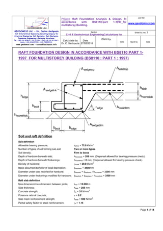
- 1. GEODOMISI Ltd. - Dr. Costas Sachpazis Civil & Geotechnical Engineering Consulting Company for Structural Engineering, Soil Mechanics, Rock Mechanics, Foundation Engineering & Retaining Structures. Tel.: (+30) 210 5238127, 210 5711263 - Fax.:+30 210 5711461 - Mobile: (+30) 6936425722 & (+44) 7585939944, www.geodomisi.com - costas@sachpazis.info Project: Raft Foundation Analysis & Design, In accordance with BS8110:part 1-1997_for multistorey Building. Job Ref. www.geodomisi.com Section Civil & Geotechnical EngineeringCalculations for Sheet no./rev. 1 Calc.Made by Dr. C. Sachpazis Date 27/02/2016 Chk'd by Date App'd by Date Page 1 of 14 RAFT FOUNDATION DESIGN IN ACCORDANCE WITH BS8110:PART 1- 1997_FOR MULTISTOREY BUILDING (BS8110 : PART 1 : 1997) hedge hboot bedgebboot aedge hslab hhcoreslab hhcorethick AsslabtopAsedgetop Asslabbtm Asedgebtm Asedgelink Soil and raft definition Soil definition Allowable bearing pressure; qallow = 75.0 kN/m 2 Number of types of soil forming sub-soil; Two or more types Soil density; Firm to loose Depth of hardcore beneath slab; hhcoreslab = 200 mm; (Dispersal allowed for bearing pressure check) Depth of hardcore beneath thickenings; hhcorethick = 0 mm; (Dispersal allowed for bearing pressure check) Density of hardcore; γhcore = 20.0 kN/m 3 Basic assumed diameter of local depression; φdepbasic = 3500mm Diameter under slab modified for hardcore; φdepslab = φdepbasic - hhcoreslab = 3300 mm Diameter under thickenings modified for hardcore; φdepthick = φdepbasic - hhcorethick = 3500 mm Raft slab definition Max dimension/max dimension between joints; lmax = 12.000 m Slab thickness; hslab = 250 mm Concrete strength; fcu = 35 N/mm 2 Poissons ratio of concrete; ν = 0.2 Slab mesh reinforcement strength; fyslab = 500 N/mm 2 Partial safety factor for steel reinforcement; γs = 1.15
- 2. GEODOMISI Ltd. - Dr. Costas Sachpazis Civil & Geotechnical Engineering Consulting Company for Structural Engineering, Soil Mechanics, Rock Mechanics, Foundation Engineering & Retaining Structures. Tel.: (+30) 210 5238127, 210 5711263 - Fax.:+30 210 5711461 - Mobile: (+30) 6936425722 & (+44) 7585939944, www.geodomisi.com - costas@sachpazis.info Project: Raft Foundation Analysis & Design, In accordance with BS8110:part 1-1997_for multistorey Building. Job Ref. www.geodomisi.com Section Civil & Geotechnical EngineeringCalculations for Sheet no./rev. 1 Calc.Made by Dr. C. Sachpazis Date 27/02/2016 Chk'd by Date App'd by Date Page 2 of 14 From C&CA document ‘Concrete ground floors’ Table 5 Minimum mesh required in top for shrinkage; A142; Actual mesh provided in top; A393 (Asslabtop = 393 mm 2 /m) Mesh provided in bottom; A393 (Asslabbtm = 393 mm 2 /m) Top mesh bar diameter; φslabtop = 10 mm Bottom mesh bar diameter; φslabbtm = 10 mm Cover to top reinforcement; ctop = 20 mm Cover to bottom reinforcement; cbtm = 40 mm Average effective depth of top reinforcement; dtslabav = hslab - ctop - φslabtop = 220 mm Average effective depth of bottom reinforcement; dbslabav = hslab - cbtm - φslabbtm = 200 mm Overall average effective depth; dslabav = (dtslabav + dbslabav)/2 = 210 mm Minimum effective depth of top reinforcement; dtslabmin = dtslabav - φslabtop/2 = 215 mm Minimum effective depth of bottom reinforcement; dbslabmin = dbslabav - φslabbtm/2 = 195 mm Edge beam definition Overall depth; hedge = 600 mm Width; bedge = 550 mm Depth of boot; hboot = 250 mm Width of boot; bboot = 250 mm Angle of chamfer to horizontal; αedge = 60 deg Strength of main bar reinforcement; fy = 500 N/mm 2 Strength of link reinforcement; fys = 500 N/mm 2 Reinforcement provided in top; 3 H25 bars (Asedgetop = 1473 mm 2 ) Reinforcement provided in bottom; 3 H20 bars (Asedgebtm = 942 mm 2 ) Link reinforcement provided; 2 H12 legs at 250 ctrs (Asv/sv = 0.905 mm) Bottom cover to links; cbeam = 40 mm Effective depth of top reinforcement; dedgetop = hedge - ctop - φslabtop - φedgelink - φedgetop/2 = 546 mm Effective depth of bottom reinforcement; dedgebtm = hedge - cbeam - φedgelink - φedgebtm/2 = 538 mm Boot main reinforcement; H8 bars at 250 ctrs (Asboot = 201 mm 2 /m) Effective depth of boot reinforcement; dboot = hboot - cbeam - φboot/2 = 206 mm Internal beam definition
- 3. GEODOMISI Ltd. - Dr. Costas Sachpazis Civil & Geotechnical Engineering Consulting Company for Structural Engineering, Soil Mechanics, Rock Mechanics, Foundation Engineering & Retaining Structures. Tel.: (+30) 210 5238127, 210 5711263 - Fax.:+30 210 5711461 - Mobile: (+30) 6936425722 & (+44) 7585939944, www.geodomisi.com - costas@sachpazis.info Project: Raft Foundation Analysis & Design, In accordance with BS8110:part 1-1997_for multistorey Building. Job Ref. www.geodomisi.com Section Civil & Geotechnical EngineeringCalculations for Sheet no./rev. 1 Calc.Made by Dr. C. Sachpazis Date 27/02/2016 Chk'd by Date App'd by Date Page 3 of 14 hint bint aint hslab hhcoreslab hhcorethick AsslabtopAsinttop Asslabbtm Asintbtm Asintlink Overall depth; hint = 550 mm Width; bint = 500 mm Angle of chamfer to horizontal; αint = 60 deg Strength of main bar reinforcement; fy = 500 N/mm 2 Strength of link reinforcement; fys = 500 N/mm 2 Reinforcement provided in top; 3 H25 bars (Asinttop = 1473 mm 2 ) Reinforcement provided in bottom; 3 H25 bars (Asintbtm = 1473 mm 2 ) Link reinforcement provided; 2 H12 legs at 225 ctrs (Asv/sv = 1.005 mm) Effective depth of top reinforcement; dinttop = hint - ctop - 2 × φslabtop - φinttop/2 = 498 mm Effective depth of bottom reinforcement; dintbtm = hint - cbeam - φintlink - φintbtm/2 = 486 mm Internal slab design checks Basic loading Slab self weight; wslab = 24 kN/m 3 × hslab = 6.0 kN/m 2 Hardcore; whcoreslab = γhcore × hhcoreslab = 4.0 kN/m 2 Applied loading Uniformly distributed dead load; wDudl = 2.0 kN/m 2 Uniformly distributed live load; wLudl = 2.5 kN/m 2 Slab load number 1
- 4. GEODOMISI Ltd. - Dr. Costas Sachpazis Civil & Geotechnical Engineering Consulting Company for Structural Engineering, Soil Mechanics, Rock Mechanics, Foundation Engineering & Retaining Structures. Tel.: (+30) 210 5238127, 210 5711263 - Fax.:+30 210 5711461 - Mobile: (+30) 6936425722 & (+44) 7585939944, www.geodomisi.com - costas@sachpazis.info Project: Raft Foundation Analysis & Design, In accordance with BS8110:part 1-1997_for multistorey Building. Job Ref. www.geodomisi.com Section Civil & Geotechnical EngineeringCalculations for Sheet no./rev. 1 Calc.Made by Dr. C. Sachpazis Date 27/02/2016 Chk'd by Date App'd by Date Page 4 of 14 Load type; Line load Dead load; wD1 = 3.0 kN/m Live load; wL1 = 2.0 kN/m Ultimate load; wult1 = 1.4 × wD1 + 1.6 × wL1 = 7.4 kN/m Line load width; b1 = 140 mm Internal slab bearing pressure check Total uniform load at formation level; wudl = wslab + whcoreslab + wDudl + wLudl = 14.5 kN/m 2 Bearing pressure beneath load number 1 Net bearing pressure available to resist line load; qnet = qallow - wudl = 60.5 kN/m 2 Net ‘ultimate’ bearing pressure available; qnetult = qnet × wult1/(wD1 + wL1) = 89.5 kN/m 2 Loaded width required at formation; lreq1 = wult1/qnetult = 0.083 m Effective loaded width at u/side slab; leff1 = max(b1, lreq1 - 2 × hhcoreslab × tan(30)) = 0.140 m Effective net ult bearing pressure at u/side slab; qnetulteff = qnetult × lreq1/leff1 = 52.9 kN/m 2 Cantilever bending moment; Mcant1 = qnetulteff × [(leff1 - b1)/2] 2 /2 = 0.0 kNm/m Reinforcement required in bottom Maximum cantilever moment; Mcantmax = 0.0 kNm/m K factor; Kslabbp = Mcantmax/(fcu × dbslabmin 2 ) = 0.000 Lever arm; zslabbp = dbslabmin × min(0.95, 0.5 + √(0.25 - Kslabbp/0.9)) = 185.3 mm Area of steel required; Asslabbpreq = Mcantmax/((1.0/γs) × fyslab × zslabbp) = 0 mm 2 /m PASS - Asslabbpreq <= Asslabbtm - Area of reinforcement provided to distribute the load is adequate The allowable bearing pressure will not be exceeded Internal slab bending and shear check Applied bending moments Span of slab; lslab = φdepslab + dtslabav = 3520 mm Ultimate self weight udl; wswult = 1.4 × wslab = 8.4 kN/m 2 Self weight moment at centre; Mcsw = wswult × lslab 2 × (1 + ν) / 64 = 2.0 kNm/m Self weight moment at edge; Mesw = wswult × lslab 2 / 32 = 3.3 kNm/m Self weight shear force at edge; Vsw = wswult × lslab / 4 = 7.4 kN/m Moments due to applied uniformly distributed loads Ultimate applied udl; wudlult = 1.4 × wDudl + 1.6 × wLudl = 6.8 kN/m 2 Moment at centre; Mcudl = wudlult × lslab 2 × (1 + ν) / 64 = 1.6 kNm/m Moment at edge; Meudl = wudlult × lslab 2 / 32 = 2.6 kNm/m Shear force at edge; Vudl = wudlult × lslab / 4 = 6.0 kN/m Moment due to load number 1 Approximate equivalent udl; wudl1 = wult1/(2 × 0.3 × lslab) = 3.5 kN/m 2 Moment at centre; Mc1 = wudl1 × lslab 2 × (1 + ν) / 64 = 0.8 kNm/m Moment at edge; Me1 = wudl1 × lslab 2 / 32 = 1.4 kNm/m Shear force at edge; V1 = wudl1 × lslab / 4 = 3.1 kN/m Resultant moments and shears Total moment at edge; MΣe = 7.2 kNm/m
- 5. GEODOMISI Ltd. - Dr. Costas Sachpazis Civil & Geotechnical Engineering Consulting Company for Structural Engineering, Soil Mechanics, Rock Mechanics, Foundation Engineering & Retaining Structures. Tel.: (+30) 210 5238127, 210 5711263 - Fax.:+30 210 5711461 - Mobile: (+30) 6936425722 & (+44) 7585939944, www.geodomisi.com - costas@sachpazis.info Project: Raft Foundation Analysis & Design, In accordance with BS8110:part 1-1997_for multistorey Building. Job Ref. www.geodomisi.com Section Civil & Geotechnical EngineeringCalculations for Sheet no./rev. 1 Calc.Made by Dr. C. Sachpazis Date 27/02/2016 Chk'd by Date App'd by Date Page 5 of 14 Total moment at centre; MΣc = 4.3 kNm/m Total shear force; VΣ = 16.5 kN/m Reinforcement required in top K factor; Kslabtop = MΣe/(fcu × dtslabav 2 ) = 0.004 Lever arm; zslabtop = dtslabav × min(0.95, 0.5 + √(0.25 - Kslabtop/0.9)) = 209.0 mm Area of steel required for bending; Asslabtopbend = MΣe/((1.0/γs) × fyslab × zslabtop) = 80 mm 2 /m Minimum area of steel required; Asslabmin = 0.0013 × hslab = 325 mm 2 /m Area of steel required; Asslabtopreq = max(Asslabtopbend, Asslabmin) = 325 mm 2 /m PASS - Asslabtopreq <= Asslabtop - Area of reinforcement provided in top to span local depressions is adequate Reinforcement required in bottom K factor; Kslabbtm = MΣc/(fcu × dbslabav 2 ) = 0.003 Lever arm; zslabbtm = dbslabav × min(0.95, 0.5 + √(0.25 - Kslabbtm/0.9)) = 190.0 mm Area of steel required for bending; Asslabbtmbend = MΣc/((1.0/γs) × fyslab × zslabbtm) = 53 mm 2 /m Area of steel required; Asslabbtmreq = max(Asslabbtmbend, Asslabmin) = 325 mm 2 /m PASS - Asslabbtmreq <= Asslabbtm - Area of reinforcement provided in bottom to span local depressions is adequate Shear check Applied shear stress; v = VΣ/dtslabmin = 0.077 N/mm 2 Tension steel ratio; ρ = 100 × Asslabtop/dtslabmin = 0.183 From BS8110-1:1997 - Table 3.8; Design concrete shear strength; vc = 0.469 N/mm 2 PASS - v <= vc - Shear capacity of the slab is adequate Internal slab deflection check Basic allowable span to depth ratio; Ratiobasic = 26.0 Moment factor; Mfactor = MΣc/dbslabav 2 = 0.109 N/mm 2 Steel service stress; fs = 2/3 × fyslab × Asslabbtmbend/Asslabbtm = 44.615 N/mm 2 Modification factor; MFslab = min(2.0, 0.55 + [(477N/mm 2 - fs)/(120 × (0.9N/mm 2 + Mfactor))]) MFslab = 2.000 Modified allowable span to depth ratio; Ratioallow = Ratiobasic × MFslab = 52.000 Actual span to depth ratio; Ratioactual = lslab/ dbslabav = 17.600 PASS - Ratioactual <= Ratioallow - Slab span to depth ratio is adequate Edge beam design checks Basic loading Hardcore; whcorethick = γhcore × hhcorethick = 0.0 kN/m 2 Edge beam Rectangular beam element; wbeam = 24 kN/m 3 × hedge × bedge = 7.9 kN/m Boot element; wboot = 24 kN/m3 × hboot × bboot = 1.5 kN/m Chamfer element; wchamfer = 24 kN/m 3 × (hedge - hslab) 2 /(2 × tan(αedge)) = 0.8 kN/m Slab element; wslabelmt = 24 kN/m 3 × hslab × (hedge - hslab)/tan(αedge) = 1.2 kN/m Edge beam self weight; wedge = wbeam + wboot + wchamfer + wslabelmt = 11.5 kN/m
- 6. GEODOMISI Ltd. - Dr. Costas Sachpazis Civil & Geotechnical Engineering Consulting Company for Structural Engineering, Soil Mechanics, Rock Mechanics, Foundation Engineering & Retaining Structures. Tel.: (+30) 210 5238127, 210 5711263 - Fax.:+30 210 5711461 - Mobile: (+30) 6936425722 & (+44) 7585939944, www.geodomisi.com - costas@sachpazis.info Project: Raft Foundation Analysis & Design, In accordance with BS8110:part 1-1997_for multistorey Building. Job Ref. www.geodomisi.com Section Civil & Geotechnical EngineeringCalculations for Sheet no./rev. 1 Calc.Made by Dr. C. Sachpazis Date 27/02/2016 Chk'd by Date App'd by Date Page 6 of 14 Edge load number 1 Load type; Longitudinal line load Dead load; wDedge1 = 13.2 kN/m Live load; wLedge1 = 0.0 kN/m Ultimate load; wultedge1 = 1.4 × wDedge1 + 1.6 × wLedge1 = 18.5 kN/m Longitudinal line load width; bedge1 = 102 mm Centroid of load from outside face of raft; xedge1 = 51 mm Edge load number 2 Load type; Longitudinal line load Dead load; wDedge2 = 16.1 kN/m Live load; wLedge2 = 5.6 kN/m Ultimate load; wultedge2 = 1.4 × wDedge2 + 1.6 × wLedge2 = 31.5 kN/m Longitudinal line load width; bedge2 = 100 mm Centroid of load from outside face of raft; xedge2 = 230 mm Edge beam bearing pressure check Effective bearing width of edge beam; bbearing = bedge + bboot + (hedge - hslab)/tan(αedge) = 1002 mm Total uniform load at formation level; wudledge = wDudl+wLudl+wedge/bbearing+whcorethick = 16.0 kN/m 2 Centroid of longitudinal and equivalent line loads from outside face of raft Load x distance for edge load 1; Moment1 = wultedge1 × xedge1 = 0.9 kN Load x distance for edge load 2; Moment2 = wultedge2 × xedge2 = 7.2 kN Sum of ultimate longitud’l and equivalent line loads; ΣUDL = 50.0 kN/m Sum of load x distances; ΣMoment = 8.2 kN Centroid of loads; xbar = ΣMoment/ΣUDL = 164 mm Initially assume no moment transferred into slab due to load/reaction eccentricity Sum of unfactored longitud’l and eff’tive line loads; ΣUDLsls = 34.9 kN/m Allowable bearing width; ballow = 2 × xbar + 2 × hhcoreslab × tan(30) = 559 mm Bearing pressure due to line/point loads; qlinepoint = ΣUDLsls/ ballow = 62.5 kN/m 2 Total applied bearing pressure; qedge = qlinepoint + wudledge = 78.4 kN/m 2 qedge > qallow - The slab is required to resist a moment due to eccentricity Now assume moment due to load/reaction eccentricity is resisted by slab Bearing width required; breq = ΣUDLsls/(qallow - wudledge) = 591 mm Effective bearing width at u/s of slab; breqeff = breq - 2 × hhcoreslab × tan(30) = 360 mm Load/reaction eccentricity; e = breqeff/2 - xbar = 16 mm Ultimate moment to be resisted by slab; Mecc = ΣUDL × e = 0.8 kNm/m From slab bending check Moment due to depression under slab (hogging); MΣe = 7.2 kNm/m Total moment to be resisted by slab top steel; Mslabtop = Mecc + MΣe = 8.1 kNm/m K factor; Kslab = Mslabtop/(fcu × dtslabmin 2 ) = 0.005 Lever arm; zslab = dtslabmin × min(0.95, 0.5 + √(0.25 - Kslab/0.9)) = 204 mm Area of steel required; Asslabreq = Mslabtop/((1.0/γs) × 460 N/mm 2 × zslab) = 99 mm 2 /m
- 7. GEODOMISI Ltd. - Dr. Costas Sachpazis Civil & Geotechnical Engineering Consulting Company for Structural Engineering, Soil Mechanics, Rock Mechanics, Foundation Engineering & Retaining Structures. Tel.: (+30) 210 5238127, 210 5711263 - Fax.:+30 210 5711461 - Mobile: (+30) 6936425722 & (+44) 7585939944, www.geodomisi.com - costas@sachpazis.info Project: Raft Foundation Analysis & Design, In accordance with BS8110:part 1-1997_for multistorey Building. Job Ref. www.geodomisi.com Section Civil & Geotechnical EngineeringCalculations for Sheet no./rev. 1 Calc.Made by Dr. C. Sachpazis Date 27/02/2016 Chk'd by Date App'd by Date Page 7 of 14 PASS - Asslabreq <= Asslabtop - Area of reinforcement provided to transfer moment into slab is adequate The allowable bearing pressure under the edge beam will not be exceeded Edge beam bending check Divider for moments due to udl’s; βudl = 12.0 Applied bending moments Span of edge beam; ledge = φdepthick + dedgetop = 4045 mm Ultimate self weight udl; wedgeult = 1.4 × wedge = 16.1 kN/m Ultimate slab udl (approx); wedgeslab = max(0 kN/m,1.4×wslab×((φdepthick/2×3/4)-(bedge+(hedge-hslab)/tan(αedge)))) wedgeslab = 4.7 kN/m Self weight and slab bending moment; Medgesw = (wedgeult + wedgeslab) × ledge 2 /βudl = 28.3 kNm Self weight shear force; Vedgesw = (wedgeult + wedgeslab) × ledge/2 = 42.0 kN Moments due to applied uniformly distributed loads Ultimate udl (approx); wedgeudl = wudlult × φdepthick/2 × 3/4 = 8.9 kN/m Bending moment; Medgeudl = wedgeudl × ledge 2 /βudl = 12.2 kNm Shear force; Vedgeudl = wedgeudl × ledge/2 = 18.1 kN Moment and shear due to load number 1 Bending moment; Medge1 = wultedge1 × ledge 2 /βudl = 25.2 kNm Shear force; Vedge1 = wultedge1 × ledge/2 = 37.4 kN Moment and shear due to load number 2 Bending moment; Medge2 = wultedge2 × ledge 2 /βudl = 43.0 kNm Shear force; Vedge2 = wultedge2 × ledge/2 = 63.7 kN Resultant moments and shears Total moment (hogging and sagging); MΣedge = 108.7 kNm Maximum shear force; VΣedge = 161.2 kN Reinforcement required in top Width of section in compression zone; bedgetop = bedge + bboot = 800 mm Average web width; bw = bedge + (hedge/tan(αedge))/2 = 723 mm K factor; Kedgetop = MΣedge/(fcu × bedgetop × dedgetop 2 ) = 0.013 Lever arm; zedgetop = dedgetop × min(0.95, 0.5 + √(0.25 - Kedgetop/0.9)) = 518 mm Area of steel required for bending; Asedgetopbend = MΣedge/((1.0/γs) × fy × zedgetop) = 482 mm 2 Minimum area of steel required; Asedgetopmin = 0.0013 × 1.0 × bw × hedge = 564 mm 2 Area of steel required; Asedgetopreq = max(Asedgetopbend, Asedgetopmin) = 564 mm 2 PASS - Asedgetopreq <= Asedgetop - Area of reinforcement provided in top of edge beams is adequate Reinforcement required in bottom Width of section in compression zone; bedgebtm = bedge + (hedge - hslab)/tan(αedge) + 0.1 × ledge = 1157 mm K factor; Kedgebtm = MΣedge/(fcu × bedgebtm × dedgebtm 2 ) = 0.009 Lever arm; zedgebtm = dedgebtm × min(0.95, 0.5 + √(0.25 - Kedgebtm/0.9)) = 511 mm Area of steel required for bending; Asedgebtmbend = MΣedge/((1.0/γs) × fy × zedgebtm) = 489 mm 2 Minimum area of steel required; Asedgebtmmin = 0.0013 × 1.0 × bw × hedge = 564 mm 2
- 8. GEODOMISI Ltd. - Dr. Costas Sachpazis Civil & Geotechnical Engineering Consulting Company for Structural Engineering, Soil Mechanics, Rock Mechanics, Foundation Engineering & Retaining Structures. Tel.: (+30) 210 5238127, 210 5711263 - Fax.:+30 210 5711461 - Mobile: (+30) 6936425722 & (+44) 7585939944, www.geodomisi.com - costas@sachpazis.info Project: Raft Foundation Analysis & Design, In accordance with BS8110:part 1-1997_for multistorey Building. Job Ref. www.geodomisi.com Section Civil & Geotechnical EngineeringCalculations for Sheet no./rev. 1 Calc.Made by Dr. C. Sachpazis Date 27/02/2016 Chk'd by Date App'd by Date Page 8 of 14 Area of steel required; Asedgebtmreq = max(Asedgebtmbend, Asedgebtmmin) = 564 mm 2 PASS - Asedgebtmreq <= Asedgebtm - Area of reinforcement provided in bottom of edge beams is adequate Edge beam shear check Applied shear stress; vedge = VΣedge/(bw × dedgetop) = 0.409 N/mm 2 Tension steel ratio; ρedge = 100 × Asedgetop/(bw × dedgetop) = 0.373 From BS8110-1:1997 - Table 3.8 Design concrete shear strength; vcedge = 0.509 N/mm 2 vedge <= vcedge + 0.4N/mm 2 - Therefore minimum links required Link area to spacing ratio required; Asv_upon_svreqedge = 0.4N/mm 2 × bw/((1.0/γs) × fys) = 0.665 mm Link area to spacing ratio provided; Asv_upon_svprovedge = Nedgelink×π×φedgelink 2 /(4×svedge) = 0.905 mm PASS - Asv_upon_svreqedge <= Asv_upon_svprovedge - Shear reinforcement provided in edge beams is adequate Boot design check Effective cantilever span; lboot = bboot + dboot/2 = 353 mm Approximate ultimate bearing pressure; qult = 1.55 × qallow = 116.3 kN/m 2 Cantilever moment; Mboot = qult × lboot 2 /2 = 7.2 kNm/m Shear force; Vboot = qult × lboot = 41.0 kN/m K factor; Kboot = Mboot/(fcu × dboot 2 ) = 0.005 Lever arm; zboot = dboot × min(0.95, 0.5 + √(0.25 - Kboot/0.9)) = 196 mm Area of reinforcement required; Asbootreq = Mboot/((1.0/γs) × fyboot × zboot) = 85 mm 2 /m PASS - Asbootreq <= Asboot - Area of reinforcement provided in boot is adequate for bending Applied shear stress; vboot = Vboot/dboot = 0.199 N/mm 2 Tension steel ratio; ρboot = 100 × Asboot/dboot = 0.098 From BS8110-1:1997 - Table 3.8 Design concrete shear strength; vcboot = 0.384 N/mm 2 PASS - vboot <= vcboot - Shear capacity of the boot is adequate Corner design checks Basic loading Corner load number 1 Load type; Line load in x direction Dead load; wDcorner1 = 13.2 kN/m Live load; wLcorner1 = 0.0 kN/m Ultimate load; wultcorner1 = 1.4 × wDcorner1 + 1.6 × wLcorner1 = 18.5 kN/m Centroid of load from outside face of raft; ycorner1 = 51 mm Corner load number 2 Load type; Line load in x direction Dead load; wDcorner2 = 16.1 kN/m Live load; wLcorner2 = 5.6 kN/m Ultimate load; wultcorner2 = 1.4 × wDcorner2 + 1.6 × wLcorner2 = 31.5 kN/m Centroid of load from outside face of raft; ycorner2 = 230 mm Corner load number 3
- 9. GEODOMISI Ltd. - Dr. Costas Sachpazis Civil & Geotechnical Engineering Consulting Company for Structural Engineering, Soil Mechanics, Rock Mechanics, Foundation Engineering & Retaining Structures. Tel.: (+30) 210 5238127, 210 5711263 - Fax.:+30 210 5711461 - Mobile: (+30) 6936425722 & (+44) 7585939944, www.geodomisi.com - costas@sachpazis.info Project: Raft Foundation Analysis & Design, In accordance with BS8110:part 1-1997_for multistorey Building. Job Ref. www.geodomisi.com Section Civil & Geotechnical EngineeringCalculations for Sheet no./rev. 1 Calc.Made by Dr. C. Sachpazis Date 27/02/2016 Chk'd by Date App'd by Date Page 9 of 14 Load type; Line load in y direction Dead load; wDcorner3 = 14.3 kN/m Live load; wLcorner3 = 0.0 kN/m Ultimate load; wultcorner3 = 1.4 × wDcorner3 + 1.6 × wLcorner3 = 20.0 kN/m Centroid of load from outside face of raft; xcorner3 = 51 mm Corner load number 4 Load type; Line load in y direction Dead load; wDcorner4 = 11.7 kN/m Live load; wLcorner4 = 0.0 kN/m Ultimate load; wultcorner4 = 1.4 × wDcorner4 + 1.6 × wLcorner4 = 16.4 kN/m Centroid of load from outside face of raft; xcorner4 = 230 mm Corner load number 5 Load type; Line load in y direction Dead load; wDcorner5 = 15.0 kN/m Live load; wLcorner5 = 0.0 kN/m Ultimate load; wultcorner5 = 1.4 × wDcorner5 + 1.6 × wLcorner5 = 21.0 kN/m Centroid of load from outside face of raft; xcorner5 = 230 mm Corner bearing pressure check Total uniform load at formation level; wudlcorner = wDudl+wLudl+wedge/bbearing+whcorethick = 16.0 kN/m 2 Net bearing press avail to resist line/point loads; qnetcorner = qallow - wudlcorner = 59.0 kN/m 2 Total line/point loads Total unfactored line load in x direction; wΣlinex = 34.9 kN/m Total ultimate line load in x direction; wΣultlinex =50.0 kN/m Total unfactored line load in y direction; wΣliney = 41.0 kN/m Total ultimate line load in y direction; wΣultliney = 57.4 kN/m Total unfactored point load; wΣpoint = 0.0 kN Total ultimate point load; wΣultpoint = 0.0 kN Length of side of sq reqd to resist line/point loads; pcorner =[wΣlinex+wΣliney+√((wΣlinex+wΣliney) 2 +4×qnetcorner×wΣpoint)]/(2×qnetcorner) pcorner = 1286 mm Bending moment about x-axis due to load/reaction eccentricity Moment due to load 1 (x line); Mx1 = max(0 kNm, wultcorner1 × pcorner × (pcorner/2 - ycorner1)) = 14.1 kNm Moment due to load 2 (x line); Mx2 = max(0 kNm, wultcorner2 × pcorner × (pcorner/2 - ycorner2)) = 16.7 kNm Total moment about x axis; MΣx = 30.8 kNm Bending moment about y-axis due to load/reaction eccentricity Moment due to load 3 (y line); My3 = max(0 kNm, wultcorner3 × pcorner × (pcorner/2 - xcorner3)) = 15.2 kNm Moment due to load 4 (y line); My4 = max(0 kNm, wultcorner4 × pcorner × (pcorner/2 - xcorner4)) = 8.7 kNm Moment due to load 5 (y line); My5 = max(0 kNm, wultcorner5 × pcorner × (pcorner/2 - xcorner5)) = 11.1 kNm Total moment about y axis; MΣy = 35.1 kNm Check top reinforcement in edge beams for load/reaction eccentric moment Max moment due to load/reaction eccentricity; MΣ = max(MΣx, MΣy) = 35.1 kNm
- 10. GEODOMISI Ltd. - Dr. Costas Sachpazis Civil & Geotechnical Engineering Consulting Company for Structural Engineering, Soil Mechanics, Rock Mechanics, Foundation Engineering & Retaining Structures. Tel.: (+30) 210 5238127, 210 5711263 - Fax.:+30 210 5711461 - Mobile: (+30) 6936425722 & (+44) 7585939944, www.geodomisi.com - costas@sachpazis.info Project: Raft Foundation Analysis & Design, In accordance with BS8110:part 1-1997_for multistorey Building. Job Ref. www.geodomisi.com Section Civil & Geotechnical EngineeringCalculations for Sheet no./rev. 1 Calc.Made by Dr. C. Sachpazis Date 27/02/2016 Chk'd by Date App'd by Date Page 10 of 14 Assume all of this moment is resisted by edge beam From edge beam design checks away from corners Moment due to edge beam spanning depression; MΣedge = 108.7 kNm Total moment to be resisted; MΣcornerbp = MΣ + MΣedge = 143.7 kNm Width of section in compression zone; bedgetop = bedge + bboot = 800 mm K factor; Kcornerbp = MΣcornerbp/(fcu × bedgetop × dedgetop 2 ) = 0.017 Lever arm; zcornerbp = dedgetop × min(0.95, 0.5 + √(0.25 - Kcornerbp/0.9)) = 518 mm Total area of top steel required; Ascornerbp = MΣcornerbp /((1.0/γs) × fy × zcornerbp) = 638 mm 2 PASS - Ascornerbp <= Asedgetop - Area of reinforcement provided to resist eccentric moment is adequate The allowable bearing pressure at the corner will not be exceeded Corner beam bending check Cantilever span of edge beam; lcorner = φdepthick/√(2) + dedgetop/2 = 2748 mm Moment and shear due to self weight Ultimate self weight udl; wedgeult = 1.4 × wedge = 16.1 kN/m Average ultimate slab udl (approx); wcornerslab = max(0 kN/m,1.4×wslab×(φdepthick/(√(2)×2)-(bedge+(hedge-hslab)/tan(αedge)))) wcornerslab = 4.1 kN/m Self weight and slab bending moment; Mcornersw = (wedgeult + wcornerslab) × lcorner 2 /2 = 76.1 kNm Self weight and slab shear force; Vcornersw = (wedgeult + wcornerslab) × lcorner = 55.4 kN Moment and shear due to udls Maximum ultimate udl; wcornerudl = ((1.4×wDudl)+(1.6×wLudl)) × φdepthick/√(2) = 16.8 kN/m Bending moment; Mcornerudl = wcornerudl × lcorner 2 /6 = 21.2 kNm Shear force; Vcornerudl = wcornerudl × lcorner/2 = 23.1 kN Moment and shear due to line loads in x direction Bending moment; Mcornerlinex = wΣultlinex × lcorner 2 /2 = 188.7 kNm Shear force; Vcornerlinex = wΣultlinex × lcorner = 137.3 kN Moment and shear due to line loads in y direction Bending moment; Mcornerliney = wΣultliney × lcorner 2 /2 = 216.7 kNm Shear force; Vcornerliney = wΣultliney × lcorner = 157.7 kN Total moments and shears due to point loads Bending moment about x axis; Mcornerpointx = 0.0 kNm Bending moment about y axis; Mcornerpointy = 0.0 kNm Shear force; Vcornerpoint = 0.0 kN Resultant moments and shears Total moment about x axis; MΣcornerx = Mcornersw+ Mcornerudl+ Mcornerliney+ Mcornerpointx = 313.9 kNm Total shear force about x axis; VΣcornerx = Vcornersw+ Vcornerudl+ Vcornerliney + Vcornerpoint = 236.2 kN Total moment about y axis; MΣcornery = Mcornersw+ Mcornerudl+ Mcornerlinex+ Mcornerpointy = 285.9 kNm Total shear force about y axis; VΣcornery = Vcornersw+ Vcornerudl+ Vcornerlinex + Vcornerpoint = 215.8 kN Deflection of both edge beams at corner will be the same therefore design for average of these moments and shears Design bending moment; MΣcorner = (MΣcornerx + MΣcornery)/2 = 299.9 kNm
- 11. GEODOMISI Ltd. - Dr. Costas Sachpazis Civil & Geotechnical Engineering Consulting Company for Structural Engineering, Soil Mechanics, Rock Mechanics, Foundation Engineering & Retaining Structures. Tel.: (+30) 210 5238127, 210 5711263 - Fax.:+30 210 5711461 - Mobile: (+30) 6936425722 & (+44) 7585939944, www.geodomisi.com - costas@sachpazis.info Project: Raft Foundation Analysis & Design, In accordance with BS8110:part 1-1997_for multistorey Building. Job Ref. www.geodomisi.com Section Civil & Geotechnical EngineeringCalculations for Sheet no./rev. 1 Calc.Made by Dr. C. Sachpazis Date 27/02/2016 Chk'd by Date App'd by Date Page 11 of 14 Design shear force; VΣcorner = (VΣcornerx + VΣcornery)/2 = 226.0 kN Reinforcement required in top of edge beam K factor; Kcorner = MΣcorner/(fcu × bedgetop × dedgetop 2 ) = 0.036 Lever arm; zcorner = dedgetop × min(0.95, 0.5 + √(0.25 - Kcorner/0.9)) = 518 mm Area of steel required for bending; Ascornerbend = MΣcorner/((1.0/γs) × fy × zcorner) = 1331 mm 2 Minimum area of steel required; Ascornermin = Asedgetopmin = 564 mm 2 Area of steel required; Ascorner = max(Ascornerbend, Ascornermin) = 1331 mm 2 PASS - Ascorner <= Asedgetop - Area of reinforcement provided in top of edge beams at corners is adequate Corner beam shear check Average web width; bw = bedge + (hedge/tan(αedge))/2 = 723 mm Applied shear stress; vcorner = VΣcorner/(bw × dedgetop) = 0.573 N/mm 2 Tension steel ratio; ρcorner = 100 × Asedgetop/(bw × dedgetop) = 0.373 From BS8110-1:1997 - Table 3.8 Design concrete shear strength; vccorner = 0.471 N/mm 2 vcorner <= vccorner + 0.4N/mm 2 - Therefore minimum links required Link area to spacing ratio required; Asv_upon_svreqcorner = 0.4N/mm 2 × bw/((1.0/γs) × fys) = 0.665 mm Link area to spacing ratio provided; Asv_upon_svprovedge = Nedgelink×π×φedgelink 2 /(4×svedge) = 0.905 mm PASS - Asv_upon_svreqcorner <= Asv_upon_svprovedge - Shear reinforcement provided in edge beams at corners is adequate Corner beam deflection check Basic allowable span to depth ratio; Ratiobasiccorner = 7.0 Moment factor; Mfactorcorner = MΣcorner/(bedgetop × dedgetop 2 ) = 1.260 N/mm 2 Steel service stress; fscorner = 2/3 × fy × Ascornerbend/Asedgetop = 301.285 N/mm 2 Modification factor; MFcorner=min(2.0,0.55+[(477N/mm 2 -fscorner)/(120×(0.9N/mm 2 +Mfactorcorner))]) MFcorner = 1.228 Modified allowable span to depth ratio; Ratioallowcorner = Ratiobasiccorner × MFcorner = 8.596 Actual span to depth ratio; Ratioactualcorner = lcorner/ dedgetop = 5.037 PASS - Ratioactualcorner <= Ratioallowcorner - Edge beam span to depth ratio is adequate Internal beam design checks Basic loading Hardcore; whcorethick = γhcore × hhcorethick = 0.0 kN/m 2 Internal beam self weight; wint=24 kN/m 3 ×[(hint×bint)+(hint-hslab) 2 /tan(αint)+2×hslab×(hint-hslab)/tan(αint)] wint = 9.9 kN/m Internal beam load number 1 Load type; Longitudinal line load Dead load; wDint1 = 15.0 kN/m Live load; wLint1 = 5.3 kN/m Ultimate load; wultint1 = 1.4 × wDint1 + 1.6 × wLint1 = 29.5 kN/m Longitudinal line load width; bint1 = 140 mm Centroid of load from centreline of beam; xint1 = 0 mm
- 12. GEODOMISI Ltd. - Dr. Costas Sachpazis Civil & Geotechnical Engineering Consulting Company for Structural Engineering, Soil Mechanics, Rock Mechanics, Foundation Engineering & Retaining Structures. Tel.: (+30) 210 5238127, 210 5711263 - Fax.:+30 210 5711461 - Mobile: (+30) 6936425722 & (+44) 7585939944, www.geodomisi.com - costas@sachpazis.info Project: Raft Foundation Analysis & Design, In accordance with BS8110:part 1-1997_for multistorey Building. Job Ref. www.geodomisi.com Section Civil & Geotechnical EngineeringCalculations for Sheet no./rev. 1 Calc.Made by Dr. C. Sachpazis Date 27/02/2016 Chk'd by Date App'd by Date Page 12 of 14 Internal beam load number 2 Load type; Full transverse line load; Dead load; wDint2 = 10.0 kN/m Live load; wLint2 = 4.0 kN/m Ultimate load; wultint2 = 1.4 × wDint2 + 1.6 × wLint2 = 20.4 kN/m Transverse line load width; bint2 = 140 mm Internal beam bearing pressure check Total uniform load at formation level; wudlint = wDudl+wLudl+whcorethick+24kN/m 3 ×hint = 17.7 kN/m 2 Effective point load due to transverse line/point loads Effective point load due to load 2 (Line load); Wint2 = wultint2 × [bint + 2×(hint - hslab)/tan(αint)] = 17.3 kN Total effective point load; Wint = 17.3 kN Minimum width of effective point load; bintmin = 140 mm Approximate longitudinal dispersal of effective point load Approx moment capacity of bottom steel; Mintbtm = (1.0/γs) × fy × 0.9 × dintbtm × Asintbtm = 279.8 kNm Max allow dispersal based on moment capacity; pintmom = [2×Mintbtm + √(4×Mintbtm 2 +2×Wint×Mintbtm×bintmin)]/Wint pintmom = 64880 mm Limiting max dispersal to say 5 x beam depth; pint = min(pintmom, 5 × hint) = 2750 mm Total dispersal length of effective point load; linteff = 2 × pint + bintmin = 5640 mm Equivalent and total beam line loads Equivalent ultimate udl of internal load 2; wintudl2 = Wint2/linteff = 3.1 kN/m Equivalent unfactored udl of internal load 2; wintudl2sls = wintudl2 × (wDint2 + wLint2)/wultint2 = 2.1 kN/m Sum of factored longitud’l and eff’tive line loads; ΣUDLint = 32.5 kN/m Sum of unfactored longitud’l and eff’tive line loads; ΣUDLslsint = 22.4 kN/m Centroid of loads from centreline of internal beam Load x distance for internal load 1; Momentint1 = wultint1 × xint1 = 0.0 kN Sum of load x distances; ΣMomentint = 0.0 kN Centroid of loads; xbarint = ΣMomentint/ΣUDLint = 0.0 mm Moment due to eccentricity to be resisted by slab; Meccint = ΣUDLint × abs(xbarint) = 0.0 kNm/m Assume moment due to eccentricity is resisted equally by top steel of slab on one side and bottom steel of slab on other From slab bending check Moment due to depression under slab (hogging); MΣe = 7.2 kNm/m Total moment to be resisted by slab top steel; Mslabtopint = Meccint/2 + MΣe = 7.2 kNm/m K factor; Kslabtopint = Mslabtopint/(fcu × dtslabmin 2 ) = 0.004 Lever arm; zslabtopint = dtslabmin × min(0.95, 0.5 + √(0.25 - Kslabtopint/0.9)) = 204 mm Area of steel required; Asslabtopintreq = Mslabtopint/((1.0/γs) × fyslab × zslabtopint) = 82 mm 2 /m PASS - Asslabtopintreq <= Asslabtop - Area of reinforcement in top of slab is adequate to transfer moment into slab Mt to be resisted by slab btm stl due to load ecc’ty; Mslabbtmint = Meccint/2 = 0.0 kNm/m K factor; Kslabbtmint = Mslabbtmint/(fcu × dbslabmin 2 ) = 0.000 Lever arm; zslabbtmint = dbslabmin × min(0.95, 0.5 + √(0.25-Kslabbtmint/0.9)) = 185 mm Area of steel required in bottom; Asslabbtmintreq = Mslabbtmint/((1.0/γs) × fyslab × zslabbtmint) = 0 mm 2 /m
- 13. GEODOMISI Ltd. - Dr. Costas Sachpazis Civil & Geotechnical Engineering Consulting Company for Structural Engineering, Soil Mechanics, Rock Mechanics, Foundation Engineering & Retaining Structures. Tel.: (+30) 210 5238127, 210 5711263 - Fax.:+30 210 5711461 - Mobile: (+30) 6936425722 & (+44) 7585939944, www.geodomisi.com - costas@sachpazis.info Project: Raft Foundation Analysis & Design, In accordance with BS8110:part 1-1997_for multistorey Building. Job Ref. www.geodomisi.com Section Civil & Geotechnical EngineeringCalculations for Sheet no./rev. 1 Calc.Made by Dr. C. Sachpazis Date 27/02/2016 Chk'd by Date App'd by Date Page 13 of 14 PASS - Asslabbtmintreq <= Asslabbtm - Area of reinforcement in bottom of slab is adequate to transfer moment into slab Bearing pressure Initially check bearing pressure based on beam soffit/chamfer width only Allowable bearing width; bbearint = bint + 2 × (hint - hslab)/tan(αint) = 846 mm Bearing pressure due to line/point loads; qlinepointint = ΣUDLslsint/bbearint = 26.5 kN/m 2 Total applied bearing pressure; qint = qlinepointint + wudlint = 44.2 kN/m 2 PASS - qint <= qallow - Allowable bearing pressure is not exceeded Internal beam bending check Divider for moments due to udl’s; βudl = 12.0 Divider for moments due to point loads; βpoint = 7.0 Applied bending moments Span of internal beam; lint = φdepthick + dinttop = 3998 mm Ultimate self weight udl; wintult = 1.4 × wint = 13.9 kN/m Ultimate slab udl (approx); wintslab = max(0 kN/m,1.4×wslab×((φdepthick×3/4)-(bint+2×(hint-hslab)/tan(αint)))) wintslab = 14.9 kN/m Self weight and slab bending moment; Mintsw = (wintult + wintslab) × lint 2 /βudl = 38.4 kNm Self weight shear force; Vintsw = (wintult + wintslab) × lint/2 = 57.6 kN Moments due to applied uniformly distributed loads Ultimate udl (approx); wintudl = wudlult × φdepthick × 3/4 = 17.9 kN/m Bending moment; Mintudl = wintudl × lint 2 /βudl = 23.8 kNm Shear force; Vintudl = wintudl × lint/2 = 35.7 kN Moment and shear due to load number 1 Bending moment; Mint1 = wultint1 × lint 2 /βudl = 39.3 kNm Shear force; Vint1 = wultint1 × lint/2 = 58.9 kN Moment and shear due to load number 2 Ultimate point load; Wint2 = wultint2 × φdepthick × 3/4 = 53.6 kN Bending moment; Mint2 = Wint2 × lint/βpoint = 30.6 kNm Shear force; Vint2 = Wint2 = 53.6 kN Resultant moments and shears Total moment (hogging and sagging); MΣint = 132.0 kNm Maximum shear force; VΣint = 205.8 kN Reinforcement required in top Width of section in compression zone; binttop = bint = 500 mm Average web width; bwint = bint + hint/tan(αint) = 818 mm K factor; Kinttop = MΣint/(fcu × binttop × dinttop 2 ) = 0.030 Lever arm; zinttop = dinttop × min(0.95, 0.5 + √(0.25 - Kinttop/0.9)) = 473 mm Area of steel required for bending; Asinttopbend = MΣint/((1.0/γs) × fy × zinttop) = 642 mm 2 Minimum area of steel; Asinttopmin = 0.0013 × bwint × hint = 585 mm 2 Area of steel required; Asinttopreq = max(Asinttopbend, Asinttopmin) = 642 mm 2
- 14. GEODOMISI Ltd. - Dr. Costas Sachpazis Civil & Geotechnical Engineering Consulting Company for Structural Engineering, Soil Mechanics, Rock Mechanics, Foundation Engineering & Retaining Structures. Tel.: (+30) 210 5238127, 210 5711263 - Fax.:+30 210 5711461 - Mobile: (+30) 6936425722 & (+44) 7585939944, www.geodomisi.com - costas@sachpazis.info Project: Raft Foundation Analysis & Design, In accordance with BS8110:part 1-1997_for multistorey Building. Job Ref. www.geodomisi.com Section Civil & Geotechnical EngineeringCalculations for Sheet no./rev. 1 Calc.Made by Dr. C. Sachpazis Date 27/02/2016 Chk'd by Date App'd by Date Page 14 of 14 PASS - Asinttopreq <= Asinttop - Area of reinforcement provided in top of internal beams is adequate Reinforcement required in bottom Width of section in compression zone; bintbtm = bint + 2 × (hint - hslab)/tan(αint) + 0.2 × lint = 1646 mm K factor; Kintbtm = MΣint/(fcu × bintbtm × dintbtm 2 ) = 0.010 Lever arm; zintbtm = dintbtm × min(0.95, 0.5 + √(0.25 - Kintbtm/0.9)) = 461 mm Area of steel required for bending; Asintbtmbend = MΣint/((1.0/γs) × fy × zintbtm) = 658 mm 2 Minimum area of steel required; Asintbtmmin = 0.0013 × 1.0 × bwint × hint = 585 mm 2 Area of steel required; Asintbtmreq = max(Asintbtmbend, Asintbtmmin) = 658 mm 2 PASS - Asintbtmreq <= Asintbtm - Area of reinforcement provided in bottom of internal beams is adequate Internal beam shear check Applied shear stress; vint = VΣint/(bwint × dinttop) = 0.506 N/mm 2 Tension steel ratio; ρint = 100 × Asinttop/(bwint × dinttop) = 0.362 From BS8110-1:1997 - Table 3.8 Design concrete shear strength; vcint = 0.477 N/mm 2 vint <= vcint + 0.4N/mm 2 - Therefore minimum links required Link area to spacing ratio required; Asv_upon_svreqint = 0.4N/mm 2 × bwint/((1.0/γs) × fys) = 0.752 mm Link area to spacing ratio provided; Asv_upon_svprovint = Nintlink×π×φintlink 2 /(4×svint) = 1.005 mm PASS - Asv_upon_svreqint <= Asv_upon_svprovint - Shear reinforcement provided in internal beams is adequate GEODOMISI Ltd. - Dr. Costas Sachpazis Civil & Geotechnical Engineering Consulting Company for Structural Engineering, Soil Mechanics, Rock Mechanics, Foundation Engineering & Retaining Structures. Tel.: (+30) 210 5238127, 210 5711263 - Fax.:+30 210 5711461 - Mobile: (+30) 6936425722 & (+44) 7585939944, www.geodomisi.com - costas@sachpazis.info