SlideShare una empresa de Scribd logo
1 de 78
Descargar para leer sin conexión
Chapter 12

WAVE FORCES ON SLENDER
CYLINDERS

12.1       Introduction
Chapters 6 through 11 have handled the hydromechanics of large (‡oating) bodies in the
sea. Attention now switches to the hydromechanics of slender cylinders. Examples of such
cylinders include the leg or brace of an o¤shore space truss structure, a pipeline or even
an umbilical cable extending down to some form of remotely controlled vehicle.


12.2       Basic Assumptions and De…nitions
A slender cylinder in this discussion implies that its diameter is small relative to the wave
length.The cylinder diameter, D, should be much less than the wave length, ¸; the methods
to be discussed here are often usable as long as D < about 0:1 to 0:2.
                                                   ¸
Derivations are done for a unit length of cylinder. Force relationships will yield a force per
unit length. This relationship must then be integrated over the cylinder length to yield a
total force. The implications of this unit length approach combined with the restriction
to slender cylinders is that the ambient water motions in the immediate vicinity of the
cylinder are all about the same at any instant in time. This is (assumed to be) true both
vertically and horizontally; the spatial variation in the undisturbed ‡ow near a unit length
of cylinder is simply neglected. A similar assumption was made for the heaving cylinder in
chapter 6, but this is not usually the case with a ship or other large structure as discussed
in the previous chapters.
The absence of a spatial variation in the ambient ‡ow as one moves from place to place near
the cylinder, makes it possible to characterize the ‡ow in the entire region of the cylinder
by the ambient ‡ow at one characteristic location. The axis of the cylinder is chosen as
that location; this simpli…es the bookkeeping.
The ‡ow around this cylinder segment will be considered to be two-dimensional - quite
analogous to strip theory for ships except that the axis of the in…nitely long cylinder is not
generally horizontal as it was for a ship. Flow components and any resulting forces parallel
  0
    J.M.J. Journée and W.W. Massie, ”OFFSHORE HYDROMECHANICS”, First Edition, January 2001,
Delft University of Technology. For updates see web site: http://www.shipmotions.nl.
12-2                       CHAPTER 12. WAVE FORCES ON SLENDER CYLINDERS

to the cylinder axis are neglected; all forces are caused by the ‡ow - and later cylinder
motion - components perpendicular to the cylinder axis.
The axis system used here is identical to that used for the waves in chapter 5, see …gure
5.2. The origin lies at the still water level with the positive z-axis directed upward. The
wave moves along the x-axis in the positive direction.
The resulting water motions come directly from chapter 5 as well:

                         @ ©w   dx          cosh k (h + z)
                   u=         =    = ³ a! ¢                ¢ cos (kx ¡ !t)            (12.1)
                          @x    dt             sinh kh
                        @©w     dz            sinh k (h + z)
                   w=        =      = ³ a! ¢                  ¢ sin (kx ¡ !t)         (12.2)
                         @z      dt               sinh kh
These can be simpli…ed for the following discussions, however. Since the location, x; of the
cylinder element is more or less …xed, the kx term in the above equations can be dropped.
For the moment, it is simplest to consider a vertical cylinder so that equation 12.1 will
yield the desired ‡ow velocity. All of this yields an undisturbed horizontal ‡ow velocity
given by:
                                           cosh k (h + z)
                         u(z; t) = ³ a ! ¢                ¢ cos (¡!t)                 (12.3)
                                               sinh kh
or at any chosen elevation, z:

                                     u(t) = ua cos(¡!t)                               (12.4)
and since cos(¡!t) = cos(!t) the sign is often dropped so that:
                                      u(t) = ua cos(!t)                               (12.5)
in which:
                    ua    = amplitude the wave-generated horizontal
                            water velocity at elevation z (m/s)
                     !    = wave frequency (rad/s)
Note that the elevation dependence in equation 12.3 has been included in ua in 12.4; this
dependence is not included speci…cally in the most of the following discussion.
Since the ‡ow is time dependent, it will have a horizontal acceleration as well. This can
be worked out to be:
                                 u(t) = ¡! ua sin (!t)
                                  _                                                (12.6)
The acceleration amplitude is thus given by:
                                          ua = ! ua
                                          _                                           (12.7)
Since potential theory describes waves so well, the above relations are assumed to hold for
any undisturbed wave ‡ow - even when viscosity is involved.


12.3        Force Components in Oscillating Flows
It is convenient to derive the relationships in this section for a smooth-surfaced vertical
cylinder. This restriction will be relaxed later in this chapter, however. Since potential
‡ows are so convenient for computations, this discussion of forces in oscillating ‡ows starts
with this idealization. The unit length of cylinder being considered is thus vertical and
submerged at some convenient depth below the water surface.
12.3. FORCE COMPONENTS IN OSCILLATING FLOWS                                                12-3

12.3.1     Inertia Forces
Remember from chapter 3 that D’Alembert proved that there is no resultant drag force
when a time-independent potential ‡ow is present. Here, it is the e¤ect of the ‡ow
accelerations that is of concern.
Consider …rst the undisturbed ambient (surrounding) ‡ow without any cylinder in it. Ac-
cording to Newton’s second law of motion, accelerations result from forces; this is univer-
sally true. Thus, the horizontal acceleration of the ambient ‡ow must be driven by a force
in the water which, in turn, must come from a horizontal pressure gradient. This pressure
gradient is present, even when there is no cylinder in the ‡ow. By examining the pressure
gradient force on a di¤erential ’block’ of ‡uid, one discovers that:

                                                  dp     du
                                                     = ½
                                                  dx     dt
                                                     = ½¢u _                             (12.8)

which is nothing more than Newton’s second law applied to a ‡uid.
Given this information, what happens when a cylinder is inserted into this pressure and ‡ow
…eld? This question is answered using an approach which has the advantage of physically
explaining the separate contributions of two separate inertia force components; a faster,
but less ’transparent’ derivation will be given later.

Pressure Gradient Force
One must ’drill a hole’ in the ambient pressure gradient …eld in order to ’insert’ the cylinder.
For now, the fact that the cylinder wall is impervious is neglected completely; the ‡ow is
still undisturbed. Any force which this undisturbed pressure …eld exerts on the cylinder
can be computed by integrating this pressure around the perimeter of the circular hole.
This integral yields, knowing that the cylinder is symmetrical with respect to the x-axis
and has a unit length:
                                         Z ¼
                            Fx1(t) = 2 ¢     p(R; µ; t) R cos µ ¢ 1 ¢ dµ                  (12.9)
                                              0

in which p(R; µ; t) is the undisturbed pressure (N/m2) on the perimeter of the circle and
R is the cylinder radius (m).
The resulting force is computed just as was done in chapter 3, using …gure 3.16.
Since the pressure di¤erence across the cylinder at any distance, y; away from the x-axis
is:

                                          ¢p = ½ ¢ u ¢ ¢x
                                                   _                                    (12.10)
where ¢x is the width of the cylinder at distance y from its axis. The integral can be
simpli…ed again so that:
                                          Z       ¼
                                                  2
                          F x1(t) = 2 ¢               ¢p(R; µ; t) ¢ R ¢ cos µ ¢ dµ      (12.11)
                                              0

After integrating one gets:
                                    Fx1(t) = ½ ¼ R2 ¢ u(t)
                                                      _                                 (12.12)
12-4                           CHAPTER 12. WAVE FORCES ON SLENDER CYLINDERS

In which one should recognize ¼R2 ½ as the mass, M1; of ‡uid displaced by the unit length
of cylinder - the mass of ‡uid one would have ’removed’ when ’drilling the hole’ in the
pressure gradient …eld.
This inertia force term stems from the pressure gradient already present in the accelerating
‡ow - even before the cylinder was installed. It is equal to the product of the mass of water
displaced by the cylinder and the acceleration already present in the undisturbed ‡ow.
This force component is fully equivalent to the Froude Krilov force mentioned in chapter
6.


Disturbance Force
The cylinder was not allowed to disturb the ‡ow when Fx1 was computed; this error is now
corrected. Obviously, the cylinder is impermeable; ‡uid cannot actually ‡ow through the
cylinder wall. The cylinder geometry forces the ‡uid to go around it modifying all the local
velocities and thus accelerations. This can only occur if a force is exerted on the ‡uid, and
this force can only come from the cylinder.
Figure 3.12, which can be found in chapter 3, shows how the streamlines diverge and
converge around a cylinder in a potential ‡ow. One way to evaluate the extra force causing
this total disturbance …eld is to examine the kinetic energy change caused by the cylinder
as was done by [Lamb, 1932]. He evaluated the kinetic energy represented by the entire
(disturbed) ‡ow …eld around the cylinder and subtracted from that value the kinetic energy
of the undisturbed ‡ow in the same - theoretically in…nite - region. This yields in equation
form:
                     ZZ
                      1                                  ZZ
                                                         1
                           1                  2             1
                E=           ½ ¢ [u (x; y; t)] dx ¢ dy ¡      ½ ¢ u2 (t) ¢ dx ¢ dy
                                                                   1                  (12.13)
                           2                                2
                   cyl: wall                       cyl: wall

It is convenient to associate this energy with some sort of equivalent mass, M2; moving
with the ambient (undisturbed ‡ow) velocity, u1; so that:

                                          1
                                       E = M2 u2
                                               1                                      (12.14)
                                          2
Lamb discovered that:
                                        M2 = ¼ R2 ½                                   (12.15)
or that M2 is simply the mass of ‡uid displaced by the cylinder segment (just as was M1)
so that:

                                     Fx2 = ¼ R2 ½ ¢ u(t)
                                                    _                                 (12.16)
Note that Fx2 has the same form as Fx1 and that they both have the same phase as well.
Fx2 is analogous to the part of the di¤raction force which was in phase with the ship
acceleration in chapter 6.
A thoughtful reader may wonder why this second force component, Fx2 , was not present
in a constant current; after all, that cylinder was then impervious to the ‡ow, too. The
answer to this question lies in the fact that Fx2 does not result from the pattern itself, but
rather from its continuous build-up and break-down which occurs only in a time-dependent
‡ow. In a constant current there is no time dependent change and thus no Fx2.
12.3. FORCE COMPONENTS IN OSCILLATING FLOWS                                              12-5

Resultant Inertia Force
Potential theory indicates that the resultant force on a …xed cylinder in an oscillating ‡ow
is the sum of two terms:


 Fx1(t) = ½ ¼ R2 ¢ u1(t)
                   _            from the ’hole’ in the undisturbed pressure gradient in the
                                ambient ‡ow. This is also know as the Froude-Krilov force.

 Fx2(t) = ½ ¼ R2 ¢ u1(t) from the ‡ow disturbance caused by the impervious cylinder.
                   _

The resultant force is then:

                                  FI (t) = Fx1 (t) + Fx2(t)
                                         = 2 ¢ ¼ R2 ½ ¢ u(t)
                                                        _                              (12.17)

Note that because this is still a potential ‡ow, there is no drag force. Also, since there is
no circulation, there is no lift, either.

Alternate Direct Calculation Approach
Another, possibly faster way to calculate the ‡ow disturbance force coe¢cient starts with
the potential function for an oscillating cylinder in still water. This approach is completely
analogous to that used in chapter 6 to determine the added mass of a ‡oating body. One
starts directly with the potential function just as was done there, and uses the Bernoulli
equation to calculate the pressure on the cylinder surface and then integrate this as was
done in chapter 3 to determine the resultant force.

Experimental Inertia Coe¢cients
The theoretical value of 2 in equation 12.17, above, is usually replaced by an experimental
coe¢cient, CM - often called the inertia coe¢cient. Remember that the theoretical
value of 2 is made up of 1 from Fx1 (the ambient pressure …eld) and 1 from Fx2, the
‡ow disturbance caused by the cylinder. In practice the 1 from the ambient pressure
…eld is usually considered to be acceptable; potential theory predicts the water motion in
undisturbed waves well. The coe¢cient from Fx2 is much less certain; the vortices in the
wake (in a real, [not potential!] ‡ow) disturb the theoretical ‡ow pattern used to determine
Fx2. This is taken into account by using a value C a - a ’coe¢cient of added mass’ -
instead. Usually Ca < 1. Note that Ca is quite analogous to the hydrodynamic mass used
in chapter 6. This is all summarize in the table below.

        Force             Force      Experimental     Theoretical      Experimental
        Component         Term       Coe¢cient        Value            Value

       Froude-Krylov       Fx1          1                 1               1
       Disturbance         Fx2          Ca                1           Usually < 1

       Inertia             FI           CM                2           Usually 1 to 2
12-6                       CHAPTER 12. WAVE FORCES ON SLENDER CYLINDERS

Remember that:
                                        jCM = 1 + Ca j                                   (12.18)

and that Ca is associated with ‡ow disturbance.
The phrase ’added mass’ has just been used above, much like it is often used in ship
hydromechanics as in chapters 6 through 9. Ca is often interpreted as ’hydrodynamic mass’
- some mysterious mass of surrounding ‡uid; this interpretation can be very misleading and
dangerous, however. Consider the following true situation taken from ship hydromechanics.
An investigator was carrying out tests to determine the hydrodynamic coe¢cients for a
‡at-bottomed barge in shallow water. Attention was focussed on its heave motion and the
in‡uence of the barge’s (relatively small) keel clearance on the hydrodynamic mass. Tests
were carried out with various (average) keel clearances so that Ca could be determined as
a function of (average) keel clearance value. Figure 12.1 shows a cross-section sketch of the
set-up.


               Figure 12.1: Cross Section of Barge Showing Keel Clearance


Since the relatively deeply loaded barge had vertical sides, these caused no waves or other
disturbance as the barge oscillated vertically; the only water that is initially really disturbed
by the vertical motions is the layer of water directly under the barge. The researcher who
carried out these tests then reasoned somewhat as follows: ”The mass of water under the
ship is directly proportional to the average keel clearance. This mass becomes less and
less as the keel clearance becomes smaller; it is therefore logical to expect Ca to approach
zero as the keel clearance becomes less and less.” His experiments proved however that C a
values became larger and larger as the keel clearance decreased.
The error here is the interpretation of Ca as if it represents a physical mass. It is not
this! Instead, C a (or even CM for that matter) should be interpreted as force per unit
acceleration or Acceleration . Returning to the experiments and the researcher above, C a
                    F orce

only represents an ’extra’ (in comparison the situation in air!) force needed to given the
barge a unit acceleration in the vertical direction. Thinking in this way, one can easily
reason that as the layer of water under the barge became thinner, it became more di¢cult
for it to ’get out of the way’ by being accelerated horizontally as the barge accelerated
downward. Conversely, it therefore took a larger force to give the barge its unit of vertical
acceleration as the keel clearance became smaller. With this reasoning, one gets the correct
answer: In the limit, Ca ! 1 as the keel clearance ! 0:
12.3. FORCE COMPONENTS IN OSCILLATING FLOWS                                             12-7

Fixed Cylinder in Waves
For a …xed cylinder in waves, one is confronted with both Fx1 and Fx2 so that equation
12.17 becomes:


                                FI (t) = Fx1(t) + F x2(t)
                                            ¼
                                       = ½ CM D2 ¢ u(t) _                            (12.19)
                                            4
in which:
             FI (t)   =   inertia force per unit cylinder length (N/m)
             ½        =   mass density of the ‡uid (kg/m3)
             CM       =   dimensionless inertia coe¢cient (-)
             u(t)
             _        =   time dependent undisturbed ‡ow acceleration (m/s2 )

CM has a theoretical value of 2 in a potential ‡ow.

Oscillating Cylinder in Still Water
One might reason that the ‡ow around an oscillating cylinder in still water would be
kinematically identical to that of an oscillating ‡ow past a …xed cylinder and that the
resulting forces would be identical. This is not the case, however.
There is no ambient dynamic pressure gradient present in still water so that the …rst inertia
force term above, Fx1 the Froude-Krilov force, is now identically equal to zero. Thus, if
the cylinder is oscillating such that its velocity is given by:
                                      _
                                      X(t) = a cos(!t)                               (12.20)

then the resultant hydrodynamic inertia force on the cylinder will be:
                                                               Ä
                           FI (t) = ¡F x2(t) = ¡C a ¢ ¼ R2 ½ ¢ X (t)                 (12.21)

The minus sign indicates that the hydrodynamic resisting force is opposite to the direction
of cylinder acceleration. The value of Ca will generally not be larger than its theoretical
value of 1. Note as well that if one is measuring forces within an instrumented pile on
a segment of this oscillating (accelerating) cylinder, one will usually also measure a force
component proportional to the mass times acceleration of the (solid) cylinder element itself.
Force measurements in the lab are often corrected for this by …rst measuring forces while
oscillating the cylinder in air before the basin is …lled with water. This force is usually
considered to be the inertia force of the measuring element itself. Only a slight error is
made here by neglecting the aerodynamic resistance caused by the accelerating ‡ow pattern
in the still air.

12.3.2      Drag Forces
Experiments have shown (see chapter 4) that a drag force proportional to U 2 and the
cylinder diameter, D; is caused by a constant current; it is only reasonable to expect a
similar force to be present in a time-dependent real ‡ow as well. Since the drag force is in
the same direction - has the same sign - as the velocity in an oscillating ‡ow, the constant
12-8                      CHAPTER 12. WAVE FORCES ON SLENDER CYLINDERS

current, U 2 ; is commonly replaced by its time-dependent counterpart, u(t) ju(t)j in order
to maintain a proper sign. Substituting relationships for u(t) and working this out yields:
                                    1
                          FD(t) =     ½ CD D u2 ¢ cos(!t) jcos(!t)j
                                              a                                     (12.22)
                                    2
in which:
                 FD (t)   =   drag force per unit length of cylinder (N/m)
                 CD       =   dimensionless drag coe¢cient (-)
                 D        =   cylinder diameter (m)
                 ua       =   water velocity amplitude (m/s)
                 !        =   circular water oscillation frequency (rad/s)
                 t        =   time (s)

One should not, however, expect the values of CD for an oscillating ‡ow to correspond
with those found in chapter 4 for a constant ‡ow. Instead, they will have to be determined
again in a time-dependent ‡ow.


12.4        Morison Equation
J.E. Morison, a graduate student at the University of California at the time, wanted to
predict wave forces on an exposed vertical pile; see [Morison et al., 1950]. He simply su-
perimposed the linear inertia force (from potential theory and oscillating ‡ows) and the
adapted quadratic drag force (from real ‡ows and constant currents) to get the following
resultant force (per unit length):

                                F (t) = Finertia (t) + Fdrag(t)                     (12.23)
or:
                    ¯                                                   ¯
                    ¯                                                   ¯
                    ¯ F (t) = ¼ ½ CM D2 ¢ u(t) + 1 ½ CD D ¢ u(t) ju(t)j ¯
                                          _                                         (12.24)
                    ¯         4                  2                      ¯

in which the …rst of these two terms is the inertia force and the second represents the drag
force.
Note that in equations 12.24 the drag and inertia force components are 90± out of phase
with each other when seen as functions of time. This is a direct consequence of the phase
shift between velocity and acceleration in an oscillatory motion; check equations 12.4 and
12.6 if necessary. Examples of this will be shown during the discussion of coe¢cients and
their determination below; see …gure 12.2 later in this chapter as well.

12.4.1      Experimental Discovery Path
Morison formulated his equation simply by hypothesizing that the superposition of two
separate and well know phenomena (drag in a current and hydrodynamic inertia in an
accelerating ‡ow) would yield a viable solution for a vertical pile in waves. This section
explains how one comes to the same equation via experiments much like those for ships.
Readers should know from earlier chapters that a common technique in marine hydrody-
namics is to oscillate a body with a chosen displacement amplitude in still water and to
12.4. MORISON EQUATION                                                                      12-9

record its displacement and the force, F (t) acting on it as functions of time. Further, the
force record is resolved into two components: one in phase with the acceleration and one
in phase with the velocity.
The …rst is determined by multiplying F (t) by ¡ cos(!t) and integrating the result to get
an inertia force; the second comes from the integral of the product of F (t) and sin(!t) to
yield a component in phase with velocity.
One single test might not tell too much, but if testing were done with di¤erent excitation
amplitudes, but at constant frequency (or period), then a plot of the amplitude of the
inertia force component versus the oscillation acceleleration amplitude would be linear; the
plot of the drag force amplitude as a function of velocity amplitude would be quadratic.
Similarly, comparison of test results carried out with cylinders of di¤erent diameter would
show that the inertia force component was proportional to D2 , while the drag force would
be linearly proportional to D.
Putting all this together would indicate that the force on a cylinder was of the form:

                          F (t) = A ¢ D2 ¢ u(t) + B ¢ D ¢ [u(t) ¢ ju(t)j]
                                           _                                             (12.25)
in which A and B are constants. It is then simple enough to use dimensional analysis and
common sense to express the unknown coe¢cients, A and B as:

                                ¼                             1
                           A=     ½ ¢ Ca       and      B=      ½ ¢ CD                   (12.26)
                                4                             2

12.4.2      Morison Equation Coe¢cient Determination
In this section, a vertical cylinder is assumed to be …xed in a horizontal sinusoidal oscillatory
‡ow. The force per unit length acting on the cylinder can be predicted using the Morison
equation with two empirical coe¢cients:
                     ¯                                                      ¯
                     ¯                                                      ¯
                     ¯F (t) = + ¼ ½ CM D 2 ¢ u(t) + 1 ½ CD D ¢ u(t) ju(t)j¯
                                              _                                          (12.27)
                     ¯           4                   2                      ¯

The values of the dimensionless force coe¢cients CD and CM can be determined experi-
mentally in a variety of ways. The …rst step, however, is always to get a recording of the
force, F; as a function of time, t. A characteristic of the ‡ow - usually the velocity - will
form the second time function.

Experimental Setup
These measurements can be made in a variety of test set-ups.

   1. Oscillating ‡ows can be generated in a large U-tube. Unfortunately the ‡ow can
      only oscillate with a limited frequency range - the natural oscillation frequency for
      the installation - unless an expensive driving system is installed. An advantage
      of a U-tube, on the other hand, is that its oscillating ‡ow is relatively ’pure’ and
      turbulence-free. A discussion continues about the applicability of results from such
      idealized tests in …eld situations, however. This topic will come up again later in this
      chapter.
12-10                      CHAPTER 12. WAVE FORCES ON SLENDER CYLINDERS

  2. A second method is to impose forced oscillations to a cylinder in still water. The
     ‡ow - when seen from the perspective of the cylinder - appears similar to that in a
     U-tube but the inertia force is not the same. Review the material above about Ca to
     understand why this is so.

  3. A third possibility is to place a vertical cylinder in regular waves. The waves are
     generated by a wave maker located at one end of the experimental tank; they are
     absorbed on an arti…cial beach at the other end. In this case it is often the wave
     height (actually the water surface elevation) which is measured as a function of time.
     The horizontal water velocity and acceleration at the location of the cylinder are in
     this latter case determined using linear wave theory - see chapter 5:

                                    ! H cosh [k (z + h)]
                          u(z; t) =       ¢                    ¢ cos (!t)
                                      2        sinh (k ¢ h)
                                  = ua (z) ¢ cos (!t)                                (12.28)
                                        !2 H cosh [k (z + h)]
                          u(z; t) = ¡
                          _                    ¢                   ¢ sin (!t)
                                          2        sinh (k ¢ h)
                                  = ¡ ! ¢ ua (z) ¢ sin (!t)                          (12.29)

        in which:

           ! = 2¼=T   =   wave frequency (rad/s)
           k = 2¼=¸   =   wave number (rad/m)
           z          =   elevation (+ is upward) from the still water level (m)
           H          =   wave height (m)
           h          =   water depth (m)
           T          =   wave period (s)
           ¸          =   wave length (m)
           ua(z)      =   amplitude of horizontal water velocity component (m/s)

Note that even though ua is now a function of z; this will not really complicate matters
when studying the forces on a short segment of a cylinder. The change in ua over such a
short distance can be neglected.
With any of these methods, the resultant force on a section of the cylinder is often measured
by mounting that section on a set of leaf springs which are equipped with strain gauges.
These - via a Wheatstone bridge circuit and a proper calibration - provide the force record,
F (t) to use in conjunction with the measured or computed u(t) and u(t)._

Data Processing
Once the necessary data time series have been obtained, one is still faced with the problem
of determining the appropriate CD and CM values. Here, again, one has several options
dependent upon the computer facilities available.
Several methods are presented here, primarily for reference purposes:

  1. Morison’s Method
     Morison, himself, suggested a simple method to determine the two unknown coe¢-
     cients, see [Morison et al., 1950]. His method was elegant in that it was possible to
12.4. MORISON EQUATION                                                            12-11

    determine the coe¢cients without the use of computers. (Computers - if available at
    all - were prohibitively expensive when he did his work.) His approach was suitable
    for hand processing and depended upon the realization that when:
    u is maximum, u is zero so that at that instant, t1; F (t1) = FD and
                     _
    u is maximum, u is zero so that at that instant, t2; F (t2) = FI :
     _
    Figure 12.2 shows a sample of an idealized measurement record. Under each of the
    above speci…c conditions, equation 12.27 can be re-arranged to yield:

                             2F
                  CD =                        at an instant t1 when u = 0
                                                                    _
                         ½D ¢ ua jua j
                              4F
                  CM   =                     at an instant t2 when u = 0         (12.30)
                         ¼ ½ D2 ¢ ! ua

    The method is simple, but it lacks accuracy because:


                  Figure 12.2: Measured Force and Velocity Record

    - A small error in the velocity record can cause a signi…cant phase error. Since the
12-12                       CHAPTER 12. WAVE FORCES ON SLENDER CYLINDERS

        curve of F (t) can be steep (especially when determining CD in …gure 12.2), this can
        cause quite some error in this coe¢cient. The e¤ect on CM is usually smaller.
        - Information from only two instants in the time record is used to determine the
        coe¢cients; the rest is thrown away.
        Morison reduced errors by averaging the coe¢cients over a large number of measure-
        ments (wave periods).
        One might try to use this same approach at other time instants in the record. The
        only di¢culty, however, is that one is then confronted with a single equation (for F
        at that instant) but with two unknown coe¢cients. This cannot be solved uniquely.
        A second equation could be created by examining the situation at a second, indepen-
        dent time instant. A generalization of this would be to use the data pairs at every
        instant with a least squares …tting technique. This is discussed below, but only after
        another approach using Fourier series has been presented.
  2. Fourier Series Approach
     An entirely di¤erent method for determining the drag and inertia coe¢cients is based
     upon the comparison of similar terms in each of two Fourier series: One for the water
     motion and one for the force. Appendix C summarizes the theory behind Fourier
     series.
     Since modern laboratory data records are stored at discrete time steps (instead of
     as continuous signals), the integrals needed to evaluate the Fourier coe¢cients are
     replaced by equivalent sums.
     Looking at this in a bit more detail, the water velocity and acceleration is already in
     a nice form as given in equation 12.28. A single Fourier series term is su¢cient to
     schematize this quite exactly. Since the inertia force, FI , is also well behaved, it can
     be ’captured’ with a single Fourier series term as well.
        The only remaining problem is the series development of the drag term; this requires
        the development of a function of form:
                                    f (t) = A cos (!t) ¢ j cos (!t)j                  (12.31)
        This has been worked out in Appendix C as well. The resulting coe¢cients (given
        there as well) for the …rst harmonic development of the quadratic drag turn out to
        be:
         Fourier
         Coe¢cient       Value
         Constant, a0 0
         Cosine, a1       8
                         3¼
                            ¢ A = 0:849 ¢ A
         Sine, b1        0
        As shown in Appendix C, the drag force, dependent upon u juj, develops into a series
        of odd-numbered harmonics in a Fourier series; only the …rst harmonic terms are used
        here. Since this has an amplitude of 3¼ times the original signal, one must multiply
                                               8

        the …rst order harmonic of the force in phase with the velocity by a factor 38¼ to get
        the amplitude of the quadratic drag force.
        Once this has been done, then the determination of C D and CM from the analysis of
        the compete force signal, F (t) is completely straightforward. Since the inertia force
        component shows up now in the b1 term of the series development, the results are:
                                 3¼                              4      b
                          CD =         ¢ a1    and     CM =           ¢ 1
                                                                   2 ½ ! u
                                                                                       (12.32)
                                4½D                            ¼D          a
12.4. MORISON EQUATION                                                                   12-13

    in which the following amplitudes are found:

                  a1 =     velocity-dependent Fourier amplitude (kg/m2)
                  b1 =     acceleration-dependent Fourier amplitude (N m)

    Notice that with this method one has used data from the entire time record in the
    determination of the Fourier series components and thus for the determination of
    CD and CM . This should be an improvement over the method used originally by
    Morison, but on the other hand, it is still only as accurate as the linearization can
    be.

 3. Least Squares Method
    A third approach treats the basic Morison equation, (12.27) as a computational
    approximation, F (t; CD; C M )computed , for the measured force record, F (t)measured . One
    is now faced with only the problem of determining the (linear) unknown coe¢cients,
    CD and CM . This is done by minimizing some residual di¤erence (or …t criterion)
    function. The method of least squares uses a residual function of the form:
                            Z T
              R(CD ; CM ) =      [F (t)measured ¡ F (t; CD; CM )computed] 2 dt          (12.33)
                               0

    in which T is now the length of the measurement record.
    Now one only needs to iteratively evaluate equation 12.33 for various values of CD
    and CM until the residual function, R(CD; C M ) is minimized. If one were to plot this
    function in three dimensions - with C D and CM on the two orthogonal horizontal
    axes and R(C D; CM ) on the vertical axis, then one would …nd a sort of ’bowl-shaped’
    function. It doesn’t take too much thought to realize that if the shape of the bottom
    of this ’bowl’ is rather ‡at, then there are many combinations of C D and CM which
    give about the same R(CD ; CM ) function value. The consequence of this is that it
    is quite di¢cult to determine the ’best’ C D and CM values exactly in a numerical
    way. On the other hand, it is theoretically possible to determine the minimum of the
                                                                       @R      @R
    function .R(CD; C M ) by setting both of its partial derivatives, @CD and @CM equal to
    zero analytically.


 4. Weighted Least Squares Method
    The least squares method, above, uses the entire time record for the determination of
    CD and CM ; it shares that advantage with the Fourier series approach. On the other
    hand, one can reason that for o¤shore design purposes, it is more important that the
    Morison equation predict the force peaks accurately than to be as precise at
    moments when the force is nearly zero. One way to improve the …tting near the peak
    forces is to weight the di¤erence found above in equation 12.33 with - for example -
    the measured or computed force value. Equation 12.33 can then become something
    like:
                          Z T
          Rw (CD ; CM ) =     [F (t)measured] 2 ¢ [F (t)measured ¡ F (t; C D; CM )computed]2 dt
                           0

    Of course the shape of the residual function - the shape of the ’bowl’ - will now be
    di¤erent and hopefully steeper and deeper (not so ‡at on its bottom). Even if this
12-14                       CHAPTER 12. WAVE FORCES ON SLENDER CYLINDERS

        is not the case, however, one can expect that a Morison equation …tted in this way
        will give a more accurate prediction of the force peaks.
        Note that most any researcher can dream up his own residual or criterion function to
        use in this approach. Residual values are usually not dimensionless quantities;
        the absolute (numerical) value of R or Rw (or any other criterion function for that
        matter) is quite irrelevant; only relative values are of interest. There is certainly
        no point in comparing them by, for example, comparing values of R with those of
        Rw . The only important matter is that of …nding the C D and CM associated with
        the minimum value of the criterion function chosen.

  5. Alternative Approach
     This method illustrates an entirely di¤erent approach to the problem. It was used
     by Massie some years ago - in an age when digital computers were still slow enough
     to make numerical integrations a cumbersome process. Instead, integrations were
     carried out using an analog computer; this could carry out these nearly instantly and
     painlessly. The analog computer was coupled to a digital computer which read the
     results of the integration and adjusted the coe¢cients accordingly for the next try.
     Such a computer was called a hybrid computer.
     The solution was based upon the following approach: First the Morison equation,
     12.27, was written in the following form:

                            F (t) = +P ¢ CM ¢ u(t) + Q ¢ C D ¢ u(t) ¢ ju(t)j
                                              _                                        (12.34)

        in which P and Q are simply known constants. Both u(t) and F (t) had been measured
        and were known functions of time.
        The special approach feature was to re-arrange equation 12.34 by solving it for u(t)_
        yielding:
                                     1    1           Q CD
                              u(t) = ¢
                              _               F (t) ¡ ¢       ¢ u(t) ¢ ju(t)j           (12.35)
                                     P CM             P CM
        Equation 12.35 is, thus, a …rst order nonlinear ordinary di¤erential equation in u(t)
        which has a given solution - the measured u(t) - but two unknown coe¢cients: 1=C M
        and CD =C M . Values for the unknown coe¢cients were set by the digital portion
        of the computer; the analog portion integrated the di¤erential equation to generate
        a computed uc(t) and simultaneously subtract it from the measured u(t) to give a
        residual which was also integrated over a time period in the analog portion. This
        integral value was the residual function to be minimized using a numerical routine in
        the attached digital computer. Notice that the criterion function is now based upon
        the velocity record instead of the force record! Of course, various weighting functions
        were tried as well.

Five di¤erent methods of determining CD and CM (or C a) coe¢cient values from a single
time record of water motion and force have been presented here. The frustrating result of
all this is that if one time record were to be analyzed with each of these methods, each
method would yield a di¤erent pair of CD and C M coe¢cient values! One can conclude -
correctly! - from this that it is impossible to determine exact values for these coe¢cients;
a tolerance of several percent is the very best one can expect.
It can also happen that one …nds widely varying values for CD or CM when comparing
results from two di¤erent time series with very similar test conditions. This can happen
12.4. MORISON EQUATION                                                                 12-15

with the drag coe¢cient, for example, when F (t) is inertia dominated as it is called.
Inertia dominated implies that the drag force is relatively unimportant so that since the
rest of the information used to compute FD is relatively small, this small value times any
coe¢cient value is still small. The converse is obviously also true: The inertia coe¢cient
value is unimportant if the force is drag dominated. More about the conditions which
can lead to this will be presented below in the discussion of the relative amplitudes of the
drag and inertia forces.

Cylinder Roughness
All of the above discussion has been for a smooth-surfaced (vertical) cylinder. Since o¤shore
structures accumulate marine growth very easily in at least the warmer seas, this modi…es
the hydrodynamic force computation in two ways: First, the cylinder can become larger -
a marine growth layer of 10 centimeters thickness will increase the cylinder’s diameter by
0.2 meters. This can be accounted for quite easily in the Morison equation. The second
in‡uence is that the roughness will in‡uence the boundary layer and vortex separation near
the cylinder. The drag and inertia coe¢cient values are generally adjusted to account for
this as will be seen later in this chapter.

Presentation Parameters
Now that C D and CM values have been found for a given ‡ow condition, it is logical to
want to present these results via a graph in which CD and CM are the dependent variables
plotted along the vertical axis. One must still choose a proper independent variable for
the horizontal axis, however. This would (ideally) include information on the wave (H; T
or something related to these), the ‡uid (½; º for example) and the cylinder (D is most
obvious choice for this, but it might include the roughness, too). Several possibilities for
making dimensionless combinations are discussed in this section.

  1. Reynolds number
     The Reynolds number for a constant current was given in chapter 4. This is modi…ed
     here for unsteady ‡ow by replacing the constant current by the amplitude of the
     oscillation velocity yielding:
                                             ua ¢ D
                                        Rn =                                     (12.36)
                                                º
     in which:
      Rn = Reynolds number (-)
      ua = ‡ow velocity amplitude (m/s)
      D = cylinder diameter (m)
      º     = kinematic viscosity (m2 /s)

  2. Froude Number
     The Froude number can now be expressed using the velocity amplitude as well as:
                                                 ua
                                          Fn = p                                     (12.37)
                                                g¢D
     in which:
      F n = Froude number (-)
      g    = acceleration of gravity (m/s2 )
12-16                       CHAPTER 12. WAVE FORCES ON SLENDER CYLINDERS

        The Froude number is associated primarily with free surface e¤ects while wave forces
        can be exerted on cylinder elements which are so far below the sea surface that no
        surface disturbance is generated. The Froude number is not really suitable for the
        present purpose, therefore.

  3. Keulegan Carpenter Number
     [Keulegan and Carpenter, 1958] determined C D and CM values for various cylinders
     in an oscillating ‡ow. They discovered that their data could be plotted reasonably
     as a function of the dimensionless Keulegan Carpenter number:
                                        ¯            ¯
                                        ¯            ¯
                                        ¯KC = ua ¢ T ¯                           (12.38)
                                        ¯        D ¯
        in which:
         KC = Keulegan Carpenter number (-)
         T     = oscillating ‡ow period (s)
        This number can be de…ned in alternate ways. In a sinusoidal wave, ua = ! ¢ xa ,
        in which xa is the (horizontal) water displacement amplitude. A bit of substitution
        then yields:
                                     water displacement amplitude         x
                         KC = 2¼ ¢                                   = 2¼ a            (12.39)
                                           cylinder diameter              D
        which is very likely an important characteristic for the wake formation in the ‡ow as
        well.
        In deep water, the water displacement amplitude xa at the sea surface is identical
        to the wave amplitude. This allows still another form in this speci…c situation:
                                        H       ³
                             KC = ¼ ¢     = 2¼ ¢ a    (deep water only)               (12.40)
                                        D       D
  4. Iversen Modulus
     Even before Keulegan and Carpenter did their work, [Iversen and Balent, 1951] sug-
     gested:

                                                   ua ¢ D
                                                   _
                                            Iv =                                      (12.41)
                                                     u2
                                                      a
        in which:
         Iv = Iversen modulus (-)
         ua = ‡ow acceleration amplitude (m/s2)
          _
        Knowing that in a sinusoidal wave ua = 2¼ ua ; and by doing a bit of algebra, one can
                                          _    T
        discover that:
                                                   2¼
                                            Iv =                                       (12.42)
                                                  KC
        KC is more convenient to use in practice, however.

  5. Sarpkaya Beta
     [Sarpkaya and Isaacson, 1981] carried out numerous experiments using a U-tube to
     generate an oscillating ‡ow. He found that the ratio:

                                                    D2
                                              ¯=                                      (12.43)
                                                   º¢T
12.4. MORISON EQUATION                                                                 12-17

     was convenient for plotting his data.
     Just as with the Iversen modulus, this can be ’processed’ a bit to reveal that:

                                                   Rn
                                             ¯=                                     (12.44)
                                                   KC
     so that this is not really anything new, either.

  6. Dimensionless Roughness
     Cylinder roughness is generally made dimensionless by dividing it by the diameter,
     yielding:

                                      "   roughness height
                                        =                                           (12.45)
                                      D   cylinder diameter


The Keulegan Carpenter number has survived as the most realistic and useful primary
independent parameter for plotting CD and CM : This is sometimes augmented by using
Rn , ¯ or D to label speci…c curves, thus introducing additional independent information.
          "


12.4.3     Typical Coe¢cient Values
Hundreds (at least) of researchers have conducted laboratory tests to determine CD and
CM coe¢cients in one way or another and often for very speci…c situations. In many cases,
their objective and/or experimental set-up limited their range of test conditions so that
their results are quite restricted, too. Typical results are listed in this section.
The results of Sarpkaya’s experiments with smooth cylinders in U-tubes are presented as
graphs of the coe¢cients CD and CM as functions of ¯ and K C: Note that in …gure 12.3
the horizontal (K C) axis is logarithmic. Individual curves on each graph are labeled with
appropriate values of ¯.
[Clauss, 1992] for example suggests drag and inertia coe¢cient values given in the following
table:

                                       Rn < 105    Rn > 105

                                       CD    CM    CD    CM
                               KC
                               < 10    1:2   2:0   0:6   2:0
                               > 10    1:2   1:5   0:6   1:5
                     Morison Coe¢cients Suggested by [Clauss, 1992]

Various design codes or rules also specify (or suggest) appropriate values for CD and CM .
Those published by [DetNorskeVeritas, 1989] or the American Petroleum Institute (API)
are the most widely accepted; the DNV suggestions for design purposes are shown in …gure
12.4.
The API as well as the SNAME have the simplest approach as listed in the table below:
12-18                 CHAPTER 12. WAVE FORCES ON SLENDER CYLINDERS


        Figure 12.3: Typical Laboratory Measurement Results from Sarpkaya
12.4. MORISON EQUATION                                                    12-19


      Figure 12.4: Suggested Drag and Inertia Coe¢cient Values from DNV
12-20                     CHAPTER 12. WAVE FORCES ON SLENDER CYLINDERS

                                         Smooth        Rough

                                   CD         CM     CD CM
                               API 0:65       1:6    1:05 1:2
                             SNAME 0:65       2:0    1:0 1:8

The following observations can be made from the above information:
 - For low values of K C, the inertia coe¢cient C M is almost equal to its theoretical value
      of 2 - at least if the K C value is used as a selection parameter. Also, one can notice
      that the drag coe¢cient CD generally increases or stays rather constant till a value
      of KC near 10 is reached.

 - One sees as well from …gure 12.3 that the CD value gets lower as ¯ increases. This is
     just the opposite of the trend observed with CM :

 - Comparison of Sarpkaya’s curves (…gure 12.3) with those from DNV (…gure 12.4) show
     that there can be quite some discrepancy in the value of CD or CM to choose.

 - The DNV curves (…gure 12.4) as well as the other design and assessment codes include
     roughness - that can easily result from marine growth, especially near the sea surface.
     The roughness in …gure 12.4 is an D ratio.
                                          ²


 - The API and SNAME recommendations seem rather simple in that they neglect the
     KC number; Clauss adds that e¤ect, but in a more simple way that suggested by
     DNV.

Comparisons
Examination and comparison of the various drag and inertia coe¢cient values presented
above shows that there is little agreement on exact values. This is true for smooth cylinder
values and even more so when a rough cylinder is involved. Di¤erences of up to roughly
40% can be found when comparing the drag or inertia coe¢cients suggested by the various
sources for a speci…c ‡ow situation.
This direct comparison of coe¢cient values can be misleading, however. In some cases a low
drag coe¢cient value can be at least partially compensated by a larger inertia coe¢cient.
After choosing a typical cylinder diameter and wave conditions, one can select appropriate
coe¢cients from each of the sources and compute the actual maximum force per unit length
upon which to base a comparison. Such an exercise can still lead to di¤erences of up to
about 30%. Luckily for survival design of o¤shore structures, the di¤erences found for
extreme wave conditions are generally less than this!
Even this comparison need not be correct. The ’purest’ approach is to select a typical
structure, and place it (in one’s mind) at a given location in the sea. Given this, one
should follow the entire procedure (given in each particular design or analysis code) to
select wave and current conditions and to translate these into forces on that structure.
These resulting forces should be compared. Carrying out such a comparison operation is
beyond the scope of this text, however.
One additional discovery that one will make when computing forces under …eld conditions
is that Sarpkaya’s data is a bit restricted for this. Indeed, the Reynolds numbers - needed
for his ¯ parameter - are much too low in nearly all laboratory situations.
12.4. MORISON EQUATION                                                                   12-21

12.4.4     Inertia or Drag Dominance
Now that CD and CM values have been presented, one should further re‡ect upon their use
and importance. The Keulegan Carpenter number can be a very important parameter for
this. Indeed, it can be used as an indication of the relative importance of drag versus inertia
forces in a particular situation. To prove this, one must work out the ratio of the amplitudes
of the drag and inertia forces. The 90± phase di¤erence between the force components is
completely neglected now; only the force component amplitudes are compared.

                                               1
                                Fdraga         ½ CD D ua juaj
                                               2
                                           =   ¼
                               Finertiaa       ½ CM D2 ! ua
                                               4
                                             2 CD jua j
                                           =                                           (12.46)
                                             ¼ CM D !
Note that the maximum value of juaj is the same as that of ua .
Since ! = 2¼=T ; then this can be reduced a bit to:

                                Fdraga     1          CD ua ¢ T
                                         =          ¢    ¢
                               Finertiaa   ¼2         CM    D
                                           1          CD
                                         =          ¢    ¢ KC                          (12.47)
                                           ¼2         CM

Since 1=¼ 2 ¼ 1=10 and the value of CD is often a bit more than half the CM value, the
two force component amplitudes are about equal when K C is in the range of roughly 15
to 20:
Remembering the earlier de…nition of KC from equation 12.39:
                                                   2¼ xa
                                           KC =                                        (12.48)
                                                    D
then this means that xa=D will be about 3; this is big enough to generate a very respectable
set of vortices.
The Morison equation includes a nonlinear (quadratic drag) term which is 90± out of phase
with the inertia force. Many o¤shore engineers want to avoid using the entire Morison
equation (and the quadratic drag computation especially) unless it is absolutely necessary.
It would be convenient to have a simple way to justify neglecting either the drag term or
the inertia term in that equation. The Keulegan Carpenter number is an excellent help
with this:
    ² For low values of K C (K C < 3), the inertia force is dominant. The ‡ow ’does not
      travel far enough’ relative to the cylinder diameter to generate much of a boundary
      layer not to mention vortices; potential ‡ow theory is still applicable. Drag can
      simply be neglected.

   ² For the next range until drag becomes signi…cant (3 < KC < 15); one will often
     linearize the drag as has been explained earlier in this chapter.

   ² There is a range of K C (15 < KC < 45) in which one cannot really avoid using the
     full Morison equation with its nonlinear drag.
12-22                       CHAPTER 12. WAVE FORCES ON SLENDER CYLINDERS

   ² For high values of KC (KC > 45), the drag force is dominant. The vortex
     shedding frequency becomes high compared to the wave frequency so the ‡ow tends
     to behave more and more like a uniform ‡ow. Inertia can be neglected. Indeed,
     the limit K C ! 1 corresponds to a constant current.


12.5       Forces on A Fixed Cylinder in Various Flows
This section describes the forces acting on a …xed cylinder in currents and/or waves. While
parts of it may seem like repetition of earlier work, its objective is to clarify the underlying
principles.

12.5.1     Current Alone
A …xed cylinder in a current alone will experience only a quadratic drag force (per unit
length) as already indicated in chapter 4. This force is assumed to be caused by the ‡ow
component:
                                       Up = U sin ·
acting perpendicular to the cylinder axis so that the force can be expressed as:
                                          1
                                   Fc =     ½ U 2 D CD sin2 ·                           (12.49)
                                          2
In these equations:

                  U     = Total velocity vector (m/s)
                  Up    = Perpendicular velocity component (m/s)
                  CD    = Drag coe¢cient for constant current (-)
                  ·     = Cone angle between the velocity vector, U;
                          and the cylinder axis.
                  Fc    = Current force per unit cylinder length (N/m)

See …gure 12.5 for a sketch showing the cone angle. The force, Fc ; will act in the direction
of Up of course; this is perpendicular to the cylinder axis and in the plane de…ned by the
cylinder axis and the approaching velocity vector, U:
Note that only the so-called cone angle, ·; is important in this computation. This is
su¢cient to describe the orientation of the cylinder relative to the current vector. It makes
no di¤erence whether the cylinder is in a vertical, horizontal or any other plane; it is only
the angle between the cylinder axis and total velocity vector which is important. (This
will be generalized to include inertia forces in waves below.)

12.5.2     Waves Alone
The time dependent ‡ow associated with waves requires the inclusion of inertia force com-
ponents into a force computation. Indeed, the basic Morison equation - derived for a unit
length of a …xed, vertical cylinder in waves is re-stated here for reference:
                     ¯                                                  ¯
                     ¯      1                     1                     ¯
                     ¯F = ¼ ½ D M u(t) + ½ C D D u(t) ju(t)j¯
                                     2 C  _                                        (12.50)
                     ¯      4                     2                     ¯
12.5. FORCES ON A FIXED CYLINDER IN VARIOUS FLOWS                                     12-23


                           Figure 12.5: Cone Angle De…nition

in which:
 F     =    Force per unit length of cylinder (N/m)
 D     =    Cylinder diameter (m)
 u(t) =     Horizontal velocity component (m/s)
 u(t) =
  _         Horizontal acceleration component (m/s2)
How can this be generalized in the light of the above information on currents for a cylinder
having a non-vertical orientation? The following steps are suggested in which the inertia
force and the drag force are considered to be separate entities until the end. The following
sequence of steps must be carried out sequentially and at each time step for which results
are desired::

  1. Determine the instantaneous water kinematics: velocity and acceleration (magnitudes
     as well as directions) in a …xed x; y; z axis system. Relate their phase to that of a
     reference such as the wave pro…le.

  2. Knowing the cylinder axis orientation (in that same x; y; z axis system), determine the
     instantaneous cone angles, ·I and ·D for the acceleration and velocity respectively.

  3. Determine the instantaneous perpendicular components of acceleration and velocity
     - up and up - as well as their directions. Use the results from the two previous steps
       _
     to do this. These two vectors will not generally be co-linear; they are both in the
     plane perpendicular to the cylinder axis, however.

  4. Evaluate the inertia and drag force components at each instant. Don’t forget that
     the drag is quadratic! The direction of each force component will correspond to that
     of its associated kinematics found in the previous step.

  5. If the force on an entire member is needed, then now is the time to integrate these
     separate force components over the length of the member in order to determine each
     resultant at that time. The member support forces - and thus the equivalent loads
     to be applied at the structure nodes - can be found by treating each member as a
     simple beam.
12-24                     CHAPTER 12. WAVE FORCES ON SLENDER CYLINDERS

  6. Since the inertia and drag force components are not generally colinear, they can
     be combined (if desired) via vector addition to yield the resulting force magnitude
     and its direction (still in a plane perpendicular to the cylinder axis). This step is
     not absolutely necessary for the computation of resulting forces on a large structure,
     however.

Note that these …ve or six steps must be repeated at each instant in time. These steps are
not di¢cult in principle, but very careful bookkeeping is essential!
In many simple cases, each of the quantities needed for this methodology will be express-
ible in terms of nicely behaved and convenient functions so that the resulting force can be
described as one or another continuous time function. On the other hand, if the wave is
irregular and thus composed of many frequency and direction components, then the neces-
sary bookkeeping becomes too cumbersome for a hand calculation. The only requirement
for the force computation is that the water acceleration and velocity be known at any time.

Special Orientations
One can check his or her understanding of the above by evaluating the forces acting on
two special cases of a horizontal cylinder in a regular wave. These are in addition to the
vertical cylinder used during the Morison equation derivation.
If the horizontal cylinder segment is oriented with its axis parallel to the direction
of wave propagation (and thus perpendicular to the wave crests), then it will experience
a vertical force which has a time trace which looks much like that for a vertical cylinder -
see …gure 12.2. This force record will be shifted 90± in phase relative to a similar record
for a vertical cylinder, however. The relative phases of the resulting drag and inertial force
components on consecutive segments of the cylinder will correspond - with some constant
shift - to that of the wave pro…le on the sea surface.
The second case has the horizontal cylinder turned parallel to the wave crests (and
thus perpendicular to the direction of wave propagation). If the cylinder is situated in a
deep water wave (in which the horizontal and vertical kinematic components have the same
magnitudes) then one will …nd a resultant force of constant magnitude which sweeps around
the cylinder once per wave period. It may seem strange, but the horizontal component of
this force will have a purely sinusoidal form (except for a possible phase shift) independent
of the fact that quadratic drag is involved. Force components on consecutive segments of
this cylinder will have identical phases in this case as compared to the previous one.

12.5.3     Currents plus Waves
It is generally accepted practice to vectorially superpose the current velocity on the velocity
resulting from the waves before calculating the drag force. In a general case the wave and
current directions will not be co-linear making a vector sum necessary. Once this has been
carried out, however, one simply has to use the sequential steps given above to determine
the resulting force at any instant.
Why is it not acceptable to compute the wave force and the current force separately? The
current has no e¤ect at all on the ‡ow accelerations so that the inertia force is unchanged
by the current. The di¢culty lies with the quadratic drag force. Since:

                                    Up + u2 < (Up + up )2
                                     2
                                          p                                            (12.51)
12.6. FORCES ON AN OSCILLATING CYLINDER IN VARIOUS FLOWS                                12-25

then a segregated treatment of the current drag and wave drag - which are superposed only
at the end of the computation - will lead to an underestimation of the forces involved.


12.6       Forces on An Oscillating Cylinder in Various Flows
Now that the hydrodynamic interaction of a …xed cylinder in a variety of ‡ows has been
explained, it is appropriate to discuss the hydrodynamic interaction of a moving cylinder
- again in a variety of ‡ow conditions.
A distinction will now have to be made between the (external) force exerted by the cylinder
on the surrounding water and the (internal, structural) force needed to cause the cylinder
(segment) to oscillate. In general, the internal force will often be one that is measured -
especially in a laboratory setting. This force includes the external hydrodynamic force but
also includes a force needed to accelerate the cylinder itself. Also, one should remember that
the hydrodynamic interaction force components will generally be in a direction opposite to
the actual velocity and acceleration of the cylinder.


12.6.1     Still Water
As indicated much earlier in this chapter, the Froude-Krilov force will be absent since
there are no ambient pressure gradients in water which is at rest. The inertia force will
be associated with a Ca value and there will be a drag force - associated with CD as well.
Analogous to the assumption made for a …xed cylinder, these forces will be associated with
the cylinder kinematics components (velocity and acceleration) which are perpendicular to
the cylinder’s axis.
The …ve steps used for determining the forces on a …xed cylinder can used here too, albeit
that the kinematics now is that of the cylinder instead of the water.


12.6.2     Current Alone
This interaction situation has already been discussed to some extent in chapter 4. One
should remember that the direction of cylinder oscillation and the current direction may
be quite di¤erent. Indeed, a vortex-induced vibration usually has its largest component
more or less perpendicular to the current direction. This results from the lift force - the
most important dynamic force in this ‡ow situation - which was discussed in chapter 4.
The drag component of the hydrodynamic interaction was quite well described in section
6 of that chapter too; there is no need to repeat that here.
Inertia forces will - in principle - now be present, too. They will be associated with a
Ca value since there is still no ambient time-dependent pressure gradient. These forces
will be opposite to the acceleration component which results exclusively from the cylinder
oscillation in this case.
In many realistic cases the approaching ‡ow velocity will be considerably larger than the
cylinder’s oscillation velocity. Also, since most oscillating cylinders are rather slender (an
umbilical cable to a ROV is an excellent example) the K C number will be large so that
inertia forces will be small anyway. In many practical situations, then, one considers only
a drag force as if it were exerted on a …xed cylinder. The drag coe¢cient is sometimes a
bit larger to account for the wider wake resulting from the cylinder oscillation.
12-26                     CHAPTER 12. WAVE FORCES ON SLENDER CYLINDERS

12.6.3      Waves Alone
The inertia and drag forces are treated entirely separately here for clarity.

Inertia Forces
Waves will contribute both a Froude-Krilov force (from the ambient, time-dependent pres-
sure gradient) as well as a disturbance force from the encounter with the solid cylinder.
The cylinder oscillation, on the other hand, plays no role in the Froude-Krilov force but
it does contribute to the disturbance term. (It is implicitly assumed here that the motion
of the cylinder is small relative to the wave length so that no phase changes result from
this displacement. It is hard to conceive of a practical situation for which this assumption
does not hold.) When one keeps in mind that the direction of cylinder oscillation need not
coincide with the wave direction, then careful bookkeeping is called for.
One …nds the following inertia terms in the equation of motion:

                          M X(t) ¯ CM MD up (t) ¡ Ca MD X(t)
                            Ä            _              Ä                           (12.52)

in which:
 M     =    Mass of the cylinder segment (kg/m)
 MD =       Displaced water mass = ¼ D2½ (kg/m)
                                      4
 up(t) =
  _         Perpendicular acceleration component from the waves (m/s2)
  Ä
 X(t) =     Cylinder acceleration (m/s2)
The symbol ¯ has been used to segregate terms from the left hand side of the full equation
of motion from those on the right. Since only selected terms are included, true equality
cannot be guaranteed. The above relationship can be re-arranged by splitting the wave
force term into its two components so that:

                   M X(t) ¯ 1 MD up(t) + Ca MD up (t) ¡ Ca MD X(t)
                     Ä           _             _              Ä                     (12.53)
If the cylinder acceleration corresponds exactly - in both magnitude and direction - to that
of the waves, then the last two terms in this latter equation cancel. This is logical; there
is then no disturbance at all and only the Froude-Krilov force remains.
In the more general case, all three hydrodynamic force components in equation 12.53 will
be present. It is often convenient to move all the force terms involving the cylinder motion
to the left hand side of the equation so that it becomes:

                           (M + C a MD ) X(t) ¯ C M M D up(t)
                                         Ä              _                           (12.54)

This isolates the (unknown) cylinder motion on the left hand side of the equation and
places the time-dependent external exciting force on the right. This right hand side can
be evaluated (without knowing the cylinder motion) as a pure time function before the
di¤erential equation of the cylinder motion is evaluated.

Drag Forces
Drag forces result from the ‡ow disturbance and wake near the cylinder. Two quite dif-
ferent approaches to the description of hydrodynamic drag are used. They are discussed
separately here.
12.6. FORCES ON AN OSCILLATING CYLINDER IN VARIOUS FLOWS                                12-27

Relative Velocity Approach It is reasonably simple to postulate that this wake de-
pends upon the motion of the water relative to the (moving) cylinder - the relative velocity:
     _
u ¡ X. It results in a drag force proportional to the square of this relative velocity so that
one …nds the following velocity-dependent terms in the equation of motion:
                                                         ¯             ¯
                               1
                      c X(t) ¯ ½ CD D (up(t) ¡ X (t)) ¯ up (t) ¡ X(t)¯
                        _                          _     ¯         _ ¯                 (12.55)
                               2
in which:
 c     = Material damping coe¢cient (N ¢ s/m)
 up(t) = Time-dependent perpendicular water velocity (m/s)
  _
 X(t) = Time-dependent cylinder velocity (m/s)
The linear damping term on the left hand side of relation 12.55 involves the internal material
damping of the cylinder itself. This has nothing to do with hydrodynamic interaction which
is concentrated on the right hand side of the relation.
Notice that the quadratic nature of the drag force makes it impossible to segregate the
(unknown) cylinder velocity from the ambient water velocity when computing this exciting
force in this way. It is not possible compute this time-dependent excitation force component
from the water motion independent of the (also time-dependent) dynamic response of the
cylinder. This requires simultaneous step-by-step solution of the di¤erential equation in
the time domain. Additionally, an extra iterative loop must be included within each
                                                               _
time step in order to successively approximate values of X until the entire di¤erential
equation is satis…ed at each time step. This makes such time-domain computations rather
time-consuming - even with modern computers.

Absolute Velocity Approach A strict interpretation of this approach uses the princi-
ples of superposition in much the same way as they are used in the hydrodynamics of larger
structures. The forces resulting from the combined motion of the cylinder in waves plus
currents is treated as if it were made up of two independent phenomena: A force caused
by the waves plus current on a stationary cylinder proportional to up jupj plus a separate
                                                                                 _
force exerted on a cylinder oscillating in still water which is proportional to X 2. This
                                                            _
approach inherently ’fails to see’ the cross product (¡2 up X) term included automatically
in the relative velocity approach. Further, since the motions of the cylinder will usually
be considerably less that those of the surrounding water, the largest contribution to the
(external) drag force will therefore come from the up jup j term. This can be left alone
on the right hand side of the equation; it can be evaluated quite easily. The relatively
        _
small X 2 term can be linearized and moved to the left hand side of the equation of mo-
tion. This linearized drag force now behaves in the same way as a linear damping; it has
the same e¤ect as increasing the structural damping which one normally includes in such
computations.
Alternatively, one can use an even more pragmatic approach by noticing that the latter two
terms of the time-dependent product in the expanded version of relation 12.55 involving
u are both smaller than the …rst term and are often of opposite sign; their combined
e¤ect will be small. One now linearizes this small e¤ect and associates it entirely with the
                   _
cylinder velocity, X; and treats it as above.
Even if the structure’s damping coe¢cient is not modi…ed, the result of either of these
approaches can be that the full di¤erential equation of motion for the cylinder has been
12-28                     CHAPTER 12. WAVE FORCES ON SLENDER CYLINDERS

linearized and that the wave-caused excitation force has been isolated on its right hand
side. Each motion is treated as if it is in a …xed axis system. It is for this reason that this
approach is often referred to as the absolute motion approach.

Comparison Designers tend to be conservative in practice. As a result of this, they tend
not to modify the linearized damping when using the absolute motion approach. Since a
dynamic system with a lower damping will often have a larger response, the absolute motion
approach most usually leads to higher predicted structural responses (internal stresses or
even displacements, for example) than does the relative velocity approach. This is indeed a
strong motivation to use the absolute velocity approach when evaluating the performance
of a proposed design. The additional advantage of having a straightforward and simple
computational procedure comes as an added bonus.

12.6.4     Currents Plus Waves
Just as with the …xed cylinder, all hydrodynamic velocity components are generally super-
posed before starting a force computation. Once this has been done, the further treatment
is identical to that for an oscillating cylinder in waves alone as discussed above.


12.7       Force Integration over A Structure
The discussion above has concentrated on the forces on a unit length of cylinder or at least
no more than a single member of a large truss structure. It is now time to integrate these
forces over the length of the cylinder in order to determine loads which are relevant for
structural analysis and design evaluation.
Since many space truss analysis computer programs work with externally applied joint
loads, the goal should be to transform the distributed hydrodynamic load on each member
of the structure to equivalent concentrated loads at the structure’s nodes. Generally, this
procedure will have to be followed during a whole series of discrete time steps in order to
generate time-dependent loadings which may be needed for a dynamic analysis.
Many computer programs for this purpose work somewhat as follows:
As preparation,

   ² The nodes of the structure are numbered sequentially.

   ² Each node is assigned a set of X; Y; Z coordinates corresponding to the intersection
     point of the member axes at that joint. (Any member eccentricity at the joint is
     neglected in the hydromechanics.)

   ² Each member is speci…ed by its diameter and the numbers of the two nodes which it
     joins. Each member’s geometric position and length is now de…ned.

Once this has been completed the following steps will be carried out for the dynamic loads
at each desired time step:

  1. The water kinematics - both combined velocities and accelerations - will be computed
     at each node location. It makes no di¤erence now whether the waves are regular or
     irregular; there can even be directional spreading or additional currents involved.
12.7. FORCE INTEGRATION OVER A STRUCTURE                                              12-29

     The result in all cases is known water kinematics at each node and at every chosen
     time.

  2. If a dynamic calculation is included, and relative velocity drag is used, then the
     structure’s velocity and acceleration at each node will have to be estimated as well.
     This is usually done by incrementally integrating the structure’s equations of motion
     by working from the previous time step.

  3. The results of the above two steps along with the known geometry allow the com-
     putation of the force per unit length (for inertia and drag forces separately) at each
     end of each member. These load intensities will have to be computed separately for
     each member and at each of its end joints.

  4. Most programs now consider each member to be a simple beam carrying a distributed
     load which is assumed to vary linearly from one end to the other. Note that both the
     intensity of the loading as well as the vector direction of the loading (about the axis
     of the cylinder) may vary along its length. (Direction variation can be present when
     the waves and current are not co-linear. It is also present when wave directional
     spreading is involved.)

  5. Basic mechanics yields the two reaction force components (relative to each member’s
     axis!) at each of its ends.

  6. It is now only a matter of bookkeeping to transform these individual member reaction
     forces into equivalent X; Y; Z force components at each joint.

  7. The above X; Y; Z components at each joint are summed to determine the total
     equivalent applied dynamic load at that joint at the chosen moment. This is the
     desired result.

  8. If relative velocity hydrodynamics is being used this result must be checked. The
     equations of motion of the structure must be integrated now to determine its new
     velocity and acceleration at the end of the time step. If these values do no correspond
     (within a chosen tolerance) with those estimated in step 2, then the above steps
     must be repeated for another iteration cycle - within this same time step - until the
     estimated and computed values appropriately coincide.

It is the extra iteration loop discussed in the last of the above steps that makes the rel-
ative velocity approach to hydromechanics so computationally ine¢cient relative to other
approaches.
Constant static loads, such as member weight and buoyant forces, can be included in the
above computation, but can be computed more e¢ciently separately before starting on the
dynamic computations. The computation principle is analogous to that for the dynamic
loads, by the way.
12-30   CHAPTER 12. WAVE FORCES ON SLENDER CYLINDERS

.
Chapter 13

SURVIVAL LOADS ON TOWER
STRUCTURES

13.1      Introduction
Chapter 12 has discussed how to compute the hydrodynamic forces on an element (of
unit length) of a single (slender) cylinder; a simpli…ed means of estimating the largest
hydrodynamic forces on an o¤shore tower structure will be handled in this chapter.
Figure 13.1 shows an isometric drawing of one of the larger o¤shore structures. The
annotations in that …gure will become clear in the course of this chapter.
Some refer to such a structure as a space frame, others see it as a space truss, some just
call it a tower. The terms ’frame’ and ’truss’ have quite di¤erent structural engineering
connotations which are not at all relevant to the hydrodynamic discussion in this chapter.
Another structural distinction is that a jacket is supported from the top by piles driven
through its legs while a tower is generally supported from below by piles driven through
sleeves - usually at the sea bed. This distinction is also irrelevant for the hydrodynamics
being discussed here; the term tower will be used more generically in this chapter to refer
to any three-dimensional structure made up from slender elements.
Imagine the bookkeeping and computational e¤ort needed to compute the total hydro-
dynamic forces on the structure shown in …gure 13.1 if this were to be done using the
elemental methods of chapter 12. Such a rigorous computation for a ’real’ tower structure
(with all its members: chords, braces, risers, etc.) is a very cumbersome undertaking,
indeed.
Many design engineers have no need for the computational accuracy suggested by a detailed
schematization of such a complex o¤shore structure - at least not during the preliminary
design phase. Instead, one more often needs a fast method of making a rough and preferably
conservative estimate of the hydrodynamic forces on a complex o¤shore structure. Such
a method can serve two purposes: Give a rough estimate for preliminary design or assure
that a detailed model is not making a major error. The objective of this chapter is to
outline a ’quick and dirty’ method to estimate the horizontal loads on a tower structure.
These loads generally yield the largest overall bending moments in the structure and thus
axial leg forces as well as the largest horizontal shear forces. These forces and moments are
also important for the foundation design. Maximum in-service bracing loads result from
  0
    J.M.J. Journée and W.W. Massie, ”OFFSHORE HYDROMECHANICS”, First Edition, January 2001,
Delft University of Technology. For updates see web site: http://www.shipmotions.nl.
13-2      CHAPTER 13. SURVIVAL LOADS ON TOWER STRUCTURES


       Figure 13.1: Typical Larger O¤shore Tower Structure
13.2. ENVIRONMENTAL CONDITIONS TO CHOOSE                                                  13-3

the horizontal wave and current loads as well.


13.1.1     Method Requirements
The results obtained with any approximation need not be exact - especially if one can
reasonably predict whether the ’real’ loads will be smaller (or larger) than the estimates.
Generally - and for preliminary design in particular - it is handy if the hydrodynamic loads
resulting from the approximation are larger than those which would follow from a more
sophisticated analysis.
When a preliminary design is based upon loads which are overestimated, it is most likely
that the resulting structure will be ’over-designed’; it will be a bit too big, or heavy, or
strong and thus probably too costly. Given this fact, then one would not expect the costs
of a structure resulting from a more detailed design to come out too high. Said in another
way, if the preliminary design survives an economic analysis, then the …nal design has a
good chance of surviving this too - at least to the extent that its total cost is determined by
hydrodynamics. An additional factor in practice is that topsides tend to become heavier
(as more equipment is added) rather than lighter during the design process. (Whether one
likes it or not, topside structures usually tend to get larger and heavier in the course of
their detailed design. This can result from equipment or throughput changes as well as
from modi…ed environmental or safety requirements.) To the extent that the tower design
is dictated by topside weight (if the water is not all that deep depending upon the sea
conditions), a bit of initial tower overdesign can prove to be handy during the later, more
detailed design analysis phase.
The objective of this chapter, therefore, is to come up with a computational procedure to
conservatively predict the hydrodynamic forces on a complex o¤shore tower structure.


13.1.2     Analysis Steps
Any hydrodynamic analysis of an o¤shore structure involves the following steps:
 1. Selection of environmental conditions (raw data).
 2. Schematization of the ambient hydrodynamics.
 3. Schematization of the structure.
 4. Computation of resulting (survival) forces and overturning moments.
These steps will be followed in the remainder of this chapter.


13.2       Environmental Conditions to Choose
Since one is looking for a maximum external load condition, it is common that this will
be caused by a maximum environmental input condition. (A signi…cant dynamic response
- which via resonance can lead to enhanced internal loads - can lead to internal response
maxima (leg forces, for example) which are caused by more moderate external sea condi-
tions. This is not considered here; it is not that common with tower structures, anyway.)
All of this means that extreme wind, wave and current conditions should be chosen for
this …rst design. Each of these involves at least two independent variables: Speed (in some
form) and direction. All of environmental inputs can be represented as vectors, but their
scalar magnitudes and directions are discussed separately here.
13-4                   CHAPTER 13. SURVIVAL LOADS ON TOWER STRUCTURES

Wind Speed

Wind loads on o¤shore structures often play a relatively minor role in comparison to the
hydrodynamic loads. For an o¤shore wind turbine, even - on which one would expect
to have a relatively high wind load - the wind load is seldom greater than the combined
wave and current load unless the structure is placed in water somewhat less than about 20
meters deep (in the North Sea). This implies that the selection of design wind conditions
is often not all that important. When one does want to estimate wind loads, a maximum
one-minute wind gust is often chosen. This wind speed is usually measured at a ’standard’
elevation of 10 meters above the sea surface.


Current Speed

Maximum current speeds are usually chosen for survival design purposes as well. One could
select a speed corresponding to a maximum spring tide current, for example. In some cases
a velocity pro…le giving the current as a function of depth will be available, too. If not, it
is of course conservative to assume that the maximum current acts over the entire depth.


Wave Height and Period

One should choose wave height and period values such that a maximum wave force or
overturning moment is obtained. A high wave is obviously needed. If one assumes that
the worst part of a storm will have a duration of about 3 to 6 hours and that an extreme
wave - if seen as a single wave - will have a period of in the order of 15 to 20 seconds,
then one can expect an exposure to something in the order of 1000 waves during the peak
of the storm. The highest wave in a series of 1000 would have a chance of exceedance of
 1000 : Substituting this in a Rayleigh wave height distribution yield a design wave height of
   1

1:86 times the design signi…cant wave height chosen. (If one works out these limits more
exactly, one should expect something more than 540 waves and less than 1440 of them;
                                                                 1        1
one thousand is pretty close to the average - by chance. If 540 and 1440 are used instead,
the wave height ratio is in the range 1.77 to 1.91; this makes no more than 5% di¤erence.)
Selecting the shortest wave period consistent with the chosen wave height will yield max-
imum water velocities and accelerations - at least near the water surface. On the other
hand, the hydrodynamics of waves with shorter periods ’die out’ faster at deeper locations;
a proper balance must be found between these two requirements. Wave breaking will, of
course, put a lower limit on the wave period for a given wave height; a very high and very
short wave will break so that one should also check any chosen combination of these to be
sure that the wave is not broken. The necessary relationships (for deep water and a quick
estimate) include:

                                                        H   1
                             ¸ = 1:56 ¢ T 2    and        <                            (13.1)
                                                        ¸   7
in which ¸ is the wave length (m), H is the wave height (m) and T is the wave period (s).
The above relations - which come directly from regular wave theory of chapter 5 - are less
dependable for larger and irregular waves at sea, however.
Since H will generally be rather large, ¸ will not be small, either. The signi…cance of this
will show up below.
13.2. ENVIRONMENTAL CONDITIONS TO CHOOSE                                                13-5


          Figure 13.2: Schematic Plan of Tower and Approaching Wave Crests

Wind, Current and Wave Directions
In general, each of these independent physical phenomena will have its own direction,
independent - at least to some extent - from that of others. This is most obvious for the
relation between the tidal current direction and the wave direction. These seldom have
much correlation. The wind direction and the wave direction - in a major storm at least -
is usually rather well (but not perfectly) correlated of course.
The conservative choice (which is easy to work with too!) is to simply assume that all
three of these phenomena are colinear; they all come from the same direction.
Be sure to keep the direction bookkeeping correct. The wind direction is speci…ed usually
as the direction from which it comes, while a current direction is most commonly stated as
the direction to which it goes. It sounds inconsistent, but a northwest wind and southeast
current go in the same vector direction.
An independent direction consideration involves the orientation of the structure (about its
vertical axis) relative to the environmental conditions. Consider a simpli…ed situation as
shown in plan in …gure 13.2. The solid circles represent the legs of the tower as seen from
above. Two possible wave and current approach directions (indicated by the wave crests)
are shown: One with crests parallel to a face of the structure (and its X axis) and one with
crests parallel to its diagonal - the D axis in the …gure. If one assumes for simplicity (for
now) that the total external horizontal force as well as the overturning moment about an
axis at the sea bed is independent of the approach direction, one will still …nd larger axial
pile forces when the wave crests are parallel to a diagonal. On the other hand, since the
horizontal shear forces within the structure are carried primarily by the bracings, waves
approaching parallel to one side of the tower will generally lead to maximum forces in these
members.This is because the entire shear load is carried by only half of the braces then;
braces parallel to the wave crests carry essentially no load.

Phasing
All of the independent environmental phenomena - wind, waves and tides - are time de-
pendent. Do all of the maxima selected above then occur at one and the same instant?
Formally, the answer to this lies in a comparison of the periods of the various phenomena.
Since the tidal period (12 h 24 min) is long relative to the wind gusts and waves, it is
13-6                  CHAPTER 13. SURVIVAL LOADS ON TOWER STRUCTURES

almost certain that a high wave or strong wind gust can occur when the tidal current is
high.
Looking next at the wind gust relative to the wave, its duration (1 minute) would be a
few wave periods long. Here, again, there is at least some …nite chance that a major wave
peak will coincide with this in time. On the other hand, many more waves will occur at
times when the design wind gust is not present!
Of course, assuming that the maxima of wind, waves and current do occur simultaneously
will lead to a conservative result; this is chosen here.

Implications
The choices made above already have signi…cant implications for the computations to be
carried out. For example, the wave length, ¸ , chosen above will be rather large relative to
the horizontal dimensions of (most) o¤shore structures being considered. This means that
there will be relatively little phase di¤erence between the ’upstream’ and ’downstream’
sides of the entire structure at any instant in time.
In chapter 12 the phase shift from one side to the other side (of a single cylinder) was
neglected. Now, with an extreme wave, the same reasoning is being applied to an en-
tire tower structure. Since phase di¤erences only tend to reduce the horizontal loads on
the structure, neglecting these will be conservative. Additionally, neglecting this phase
di¤erence will simplify the formulation of the structural model enormously.
Since the wave is relatively high, the Keulegan Carpenter number KC = ¼¢H (at the sea
                                                                              D
surface and in deep water) will tend to be high as well. This indicates that the wave forces
will tend to be drag dominated - at least at the sea surface where they are largest.
Note that if the structure is not in deep water, the actual KC value will be even higher
than that estimated above; this can be checked by using the complete equations - rather
than deep water approximations - to describe the water motion. When the current is added
to the water velocity caused by the wave, then this drag dominance becomes even more
pronounced, of course. In all cases, the water velocity will decrease with depth so that the
KC value will decrease as well. One can expect the inertia force to increase in importance
as one moves down along the structure. A signi…cant current can prevent it from ever
playing much role, however.
Remember too from wave kinematics that the maximum horizontal water velocity in a
wave occurs under that wave crest or trough. The total resulting force (integrated over
the structure) will be greatest when the wave crest passes by, simply because more of the
structure is then exposed to the wave. Wave kinematics will have to be predicted over the
entire height from the sea bed to the wave crest in order to carry out such a computation.


13.3      Ambient Flow Schematizations
This section discusses the numerical models needed to translate the raw data on environ-
mental conditions into input data for a force model.

Wind
Wind velocity distributions have been discussed in chapter 4. If - as is standard meteoro-
logical practice - the wind is given at a standard elevation of 10 meters above mean sea
Wave force
Wave force
Wave force
Wave force
Wave force
Wave force
Wave force
Wave force
Wave force
Wave force
Wave force
Wave force
Wave force
Wave force
Wave force
Wave force
Wave force
Wave force
Wave force
Wave force
Wave force
Wave force
Wave force
Wave force
Wave force
Wave force
Wave force
Wave force
Wave force
Wave force
Wave force
Wave force
Wave force
Wave force
Wave force
Wave force
Wave force
Wave force
Wave force
Wave force
Wave force
Wave force

Más contenido relacionado

La actualidad más candente

Lecture 10 bending stresses in beams
Lecture 10 bending stresses in beamsLecture 10 bending stresses in beams
Lecture 10 bending stresses in beamsDeepak Agarwal
 
Design Procedure of Singly,Doubly & T-Beam(As Per ACI code)
Design Procedure of Singly,Doubly & T-Beam(As Per ACI code)Design Procedure of Singly,Doubly & T-Beam(As Per ACI code)
Design Procedure of Singly,Doubly & T-Beam(As Per ACI code)Jahidur Rahman
 
Theories of columns
Theories of columnsTheories of columns
Theories of columnsJISHNU V
 
Deflection in beams
Deflection in beamsDeflection in beams
Deflection in beamsYatin Singh
 
Unit 3 flexibility-anujajape
Unit 3 flexibility-anujajapeUnit 3 flexibility-anujajape
Unit 3 flexibility-anujajapeanujajape
 
Lecture 11 Shear Strength of Soil CE240
Lecture 11 Shear Strength of Soil CE240Lecture 11 Shear Strength of Soil CE240
Lecture 11 Shear Strength of Soil CE240Wajahat Ullah
 
Stiffness matrix method for beam , examples ce525
Stiffness  matrix method for beam , examples   ce525Stiffness  matrix method for beam , examples   ce525
Stiffness matrix method for beam , examples ce525KAMARAN SHEKHA
 
Geotechnical Engineering-I [Lec #19: Consolidation-III]
Geotechnical Engineering-I [Lec #19: Consolidation-III]Geotechnical Engineering-I [Lec #19: Consolidation-III]
Geotechnical Engineering-I [Lec #19: Consolidation-III]Muhammad Irfan
 
Geotechnical Engineering-II [Lec #23: Rankine Earth Pressure Theory]
Geotechnical Engineering-II [Lec #23: Rankine Earth Pressure Theory]Geotechnical Engineering-II [Lec #23: Rankine Earth Pressure Theory]
Geotechnical Engineering-II [Lec #23: Rankine Earth Pressure Theory]Muhammad Irfan
 
Structural dynamics and earthquake engineering
Structural dynamics and earthquake engineeringStructural dynamics and earthquake engineering
Structural dynamics and earthquake engineeringBharat Khadka
 
Numerical problem , single ,group pile capacity (usefulsearch.org) (useful se...
Numerical problem , single ,group pile capacity (usefulsearch.org) (useful se...Numerical problem , single ,group pile capacity (usefulsearch.org) (useful se...
Numerical problem , single ,group pile capacity (usefulsearch.org) (useful se...Make Mannan
 
Redistribution of moments-Part-1
Redistribution of moments-Part-1Redistribution of moments-Part-1
Redistribution of moments-Part-1Subhash Patankar
 
Is code underremead pile Bearing capacity
Is code underremead pile Bearing capacityIs code underremead pile Bearing capacity
Is code underremead pile Bearing capacityMake Mannan
 

La actualidad más candente (20)

Shear Stress; Id no.: 10.01.03.033
Shear Stress; Id no.: 10.01.03.033Shear Stress; Id no.: 10.01.03.033
Shear Stress; Id no.: 10.01.03.033
 
Lecture 10 bending stresses in beams
Lecture 10 bending stresses in beamsLecture 10 bending stresses in beams
Lecture 10 bending stresses in beams
 
Design Procedure of Singly,Doubly & T-Beam(As Per ACI code)
Design Procedure of Singly,Doubly & T-Beam(As Per ACI code)Design Procedure of Singly,Doubly & T-Beam(As Per ACI code)
Design Procedure of Singly,Doubly & T-Beam(As Per ACI code)
 
Hydrostatics and stability
Hydrostatics and stabilityHydrostatics and stability
Hydrostatics and stability
 
Theories of columns
Theories of columnsTheories of columns
Theories of columns
 
Deflection in beams
Deflection in beamsDeflection in beams
Deflection in beams
 
Design of slabs 1
Design of slabs 1Design of slabs 1
Design of slabs 1
 
Unit 3 flexibility-anujajape
Unit 3 flexibility-anujajapeUnit 3 flexibility-anujajape
Unit 3 flexibility-anujajape
 
Lecture 11 Shear Strength of Soil CE240
Lecture 11 Shear Strength of Soil CE240Lecture 11 Shear Strength of Soil CE240
Lecture 11 Shear Strength of Soil CE240
 
Stiffness matrix method for beam , examples ce525
Stiffness  matrix method for beam , examples   ce525Stiffness  matrix method for beam , examples   ce525
Stiffness matrix method for beam , examples ce525
 
Geotechnical Engineering-I [Lec #19: Consolidation-III]
Geotechnical Engineering-I [Lec #19: Consolidation-III]Geotechnical Engineering-I [Lec #19: Consolidation-III]
Geotechnical Engineering-I [Lec #19: Consolidation-III]
 
Lecture 3 foundation settlement
Lecture 3 foundation settlementLecture 3 foundation settlement
Lecture 3 foundation settlement
 
Geotechnical Engineering-II [Lec #23: Rankine Earth Pressure Theory]
Geotechnical Engineering-II [Lec #23: Rankine Earth Pressure Theory]Geotechnical Engineering-II [Lec #23: Rankine Earth Pressure Theory]
Geotechnical Engineering-II [Lec #23: Rankine Earth Pressure Theory]
 
WAVES
WAVESWAVES
WAVES
 
Structural dynamics and earthquake engineering
Structural dynamics and earthquake engineeringStructural dynamics and earthquake engineering
Structural dynamics and earthquake engineering
 
Numerical problem , single ,group pile capacity (usefulsearch.org) (useful se...
Numerical problem , single ,group pile capacity (usefulsearch.org) (useful se...Numerical problem , single ,group pile capacity (usefulsearch.org) (useful se...
Numerical problem , single ,group pile capacity (usefulsearch.org) (useful se...
 
Deep beam
Deep beamDeep beam
Deep beam
 
Redistribution of moments-Part-1
Redistribution of moments-Part-1Redistribution of moments-Part-1
Redistribution of moments-Part-1
 
Sfd bmd
Sfd  bmdSfd  bmd
Sfd bmd
 
Is code underremead pile Bearing capacity
Is code underremead pile Bearing capacityIs code underremead pile Bearing capacity
Is code underremead pile Bearing capacity
 

Destacado

Rigid Body Dynamic
Rigid Body DynamicRigid Body Dynamic
Rigid Body DynamicNabeh Wildan
 
Tether chain, wire, and synthethic for offshore
Tether chain, wire, and synthethic for offshoreTether chain, wire, and synthethic for offshore
Tether chain, wire, and synthethic for offshoreNabeh Wildan
 
cross sectional properties of structural members
cross sectional properties of structural memberscross sectional properties of structural members
cross sectional properties of structural membersNabeh Wildan
 
Its undergraduate-11557-4305100021-paper
Its undergraduate-11557-4305100021-paperIts undergraduate-11557-4305100021-paper
Its undergraduate-11557-4305100021-paperDani Ermawan
 
Rigid body dynamic
Rigid body dynamicRigid body dynamic
Rigid body dynamicNabeh Wildan
 
Motion of particles in fluid (GIKI)
Motion of particles in fluid (GIKI)Motion of particles in fluid (GIKI)
Motion of particles in fluid (GIKI)SAFFI Ud Din Ahmad
 
Chapter 6 concrete dam engineering with examples
Chapter 6 concrete dam engineering with examplesChapter 6 concrete dam engineering with examples
Chapter 6 concrete dam engineering with examplesMohsin Siddique
 
Hibbeler chapter10
Hibbeler chapter10Hibbeler chapter10
Hibbeler chapter10ahmedalnamer
 
Calculo de engranajes dientes rectos
Calculo de engranajes dientes rectosCalculo de engranajes dientes rectos
Calculo de engranajes dientes rectosJose Mecanico
 
PMP Chap 7 - Project Cost Management - Part 1
PMP Chap 7 - Project Cost Management - Part 1PMP Chap 7 - Project Cost Management - Part 1
PMP Chap 7 - Project Cost Management - Part 1Anand Bobade
 

Destacado (11)

Launch analysis
Launch analysisLaunch analysis
Launch analysis
 
Rigid Body Dynamic
Rigid Body DynamicRigid Body Dynamic
Rigid Body Dynamic
 
Tether chain, wire, and synthethic for offshore
Tether chain, wire, and synthethic for offshoreTether chain, wire, and synthethic for offshore
Tether chain, wire, and synthethic for offshore
 
cross sectional properties of structural members
cross sectional properties of structural memberscross sectional properties of structural members
cross sectional properties of structural members
 
Its undergraduate-11557-4305100021-paper
Its undergraduate-11557-4305100021-paperIts undergraduate-11557-4305100021-paper
Its undergraduate-11557-4305100021-paper
 
Rigid body dynamic
Rigid body dynamicRigid body dynamic
Rigid body dynamic
 
Motion of particles in fluid (GIKI)
Motion of particles in fluid (GIKI)Motion of particles in fluid (GIKI)
Motion of particles in fluid (GIKI)
 
Chapter 6 concrete dam engineering with examples
Chapter 6 concrete dam engineering with examplesChapter 6 concrete dam engineering with examples
Chapter 6 concrete dam engineering with examples
 
Hibbeler chapter10
Hibbeler chapter10Hibbeler chapter10
Hibbeler chapter10
 
Calculo de engranajes dientes rectos
Calculo de engranajes dientes rectosCalculo de engranajes dientes rectos
Calculo de engranajes dientes rectos
 
PMP Chap 7 - Project Cost Management - Part 1
PMP Chap 7 - Project Cost Management - Part 1PMP Chap 7 - Project Cost Management - Part 1
PMP Chap 7 - Project Cost Management - Part 1
 

Similar a Wave force

Introduction to basic principles of fluid mechanics
Introduction to basic principles of fluid mechanicsIntroduction to basic principles of fluid mechanics
Introduction to basic principles of fluid mechanicsAlwin Johnnie DoraiRaj
 
120715 - LMAJdS paper - HydroVision 2012 presentation - 14 pages
120715 - LMAJdS paper - HydroVision 2012 presentation - 14 pages120715 - LMAJdS paper - HydroVision 2012 presentation - 14 pages
120715 - LMAJdS paper - HydroVision 2012 presentation - 14 pagesLuc-Marie Jeudy de Sauceray
 
ME3330_FluidFlow_Lab_Report
ME3330_FluidFlow_Lab_ReportME3330_FluidFlow_Lab_Report
ME3330_FluidFlow_Lab_ReportJordan Benn
 
WavesAppendix.pdf
WavesAppendix.pdfWavesAppendix.pdf
WavesAppendix.pdfcfisicaster
 
Transport phenomena Solved problems
Transport phenomena Solved problemsTransport phenomena Solved problems
Transport phenomena Solved problemsWolkite University
 
CZMAR_lecture L3A1_and Assignment for Class
CZMAR_lecture L3A1_and Assignment for ClassCZMAR_lecture L3A1_and Assignment for Class
CZMAR_lecture L3A1_and Assignment for ClassDoomDoctor
 
Chapter 3
Chapter 3Chapter 3
Chapter 3nimcan1
 
slidesWaveRegular.pdf
slidesWaveRegular.pdfslidesWaveRegular.pdf
slidesWaveRegular.pdfcfisicaster
 
Me 2204 fluid mechanics and machinery
Me 2204 fluid mechanics and machineryMe 2204 fluid mechanics and machinery
Me 2204 fluid mechanics and machineryanish antony
 

Similar a Wave force (20)

Introduction to basic principles of fluid mechanics
Introduction to basic principles of fluid mechanicsIntroduction to basic principles of fluid mechanics
Introduction to basic principles of fluid mechanics
 
Chapter9.pdf
Chapter9.pdfChapter9.pdf
Chapter9.pdf
 
120715 - LMAJdS paper - HydroVision 2012 presentation - 14 pages
120715 - LMAJdS paper - HydroVision 2012 presentation - 14 pages120715 - LMAJdS paper - HydroVision 2012 presentation - 14 pages
120715 - LMAJdS paper - HydroVision 2012 presentation - 14 pages
 
Drag force & Lift
Drag force & LiftDrag force & Lift
Drag force & Lift
 
ME3330_FluidFlow_Lab_Report
ME3330_FluidFlow_Lab_ReportME3330_FluidFlow_Lab_Report
ME3330_FluidFlow_Lab_Report
 
Velocity And acceleration
Velocity And accelerationVelocity And acceleration
Velocity And acceleration
 
WavesAppendix.pdf
WavesAppendix.pdfWavesAppendix.pdf
WavesAppendix.pdf
 
Chapter 4. diffrential
Chapter 4. diffrentialChapter 4. diffrential
Chapter 4. diffrential
 
Transport phenomena Solved problems
Transport phenomena Solved problemsTransport phenomena Solved problems
Transport phenomena Solved problems
 
Solution baupc 2004
Solution baupc 2004Solution baupc 2004
Solution baupc 2004
 
CZMAR_lecture L3A1_and Assignment for Class
CZMAR_lecture L3A1_and Assignment for ClassCZMAR_lecture L3A1_and Assignment for Class
CZMAR_lecture L3A1_and Assignment for Class
 
Chapter 3
Chapter 3Chapter 3
Chapter 3
 
cfd ahmed body
cfd ahmed bodycfd ahmed body
cfd ahmed body
 
TWO-DIMENSIONAL IDEAL FLOW (Chapter 6)
TWO-DIMENSIONAL IDEAL FLOW (Chapter 6)TWO-DIMENSIONAL IDEAL FLOW (Chapter 6)
TWO-DIMENSIONAL IDEAL FLOW (Chapter 6)
 
NS Equation .pdf
NS Equation .pdfNS Equation .pdf
NS Equation .pdf
 
slidesWaveRegular.pdf
slidesWaveRegular.pdfslidesWaveRegular.pdf
slidesWaveRegular.pdf
 
Forced convection
Forced convectionForced convection
Forced convection
 
IARE_SOM_II_PPT.pdf
IARE_SOM_II_PPT.pdfIARE_SOM_II_PPT.pdf
IARE_SOM_II_PPT.pdf
 
Me 2204 fluid mechanics and machinery
Me 2204 fluid mechanics and machineryMe 2204 fluid mechanics and machinery
Me 2204 fluid mechanics and machinery
 
Ijems 6(4) 188 197
Ijems 6(4) 188 197Ijems 6(4) 188 197
Ijems 6(4) 188 197
 

Wave force

  • 1. Chapter 12 WAVE FORCES ON SLENDER CYLINDERS 12.1 Introduction Chapters 6 through 11 have handled the hydromechanics of large (‡oating) bodies in the sea. Attention now switches to the hydromechanics of slender cylinders. Examples of such cylinders include the leg or brace of an o¤shore space truss structure, a pipeline or even an umbilical cable extending down to some form of remotely controlled vehicle. 12.2 Basic Assumptions and De…nitions A slender cylinder in this discussion implies that its diameter is small relative to the wave length.The cylinder diameter, D, should be much less than the wave length, ¸; the methods to be discussed here are often usable as long as D < about 0:1 to 0:2. ¸ Derivations are done for a unit length of cylinder. Force relationships will yield a force per unit length. This relationship must then be integrated over the cylinder length to yield a total force. The implications of this unit length approach combined with the restriction to slender cylinders is that the ambient water motions in the immediate vicinity of the cylinder are all about the same at any instant in time. This is (assumed to be) true both vertically and horizontally; the spatial variation in the undisturbed ‡ow near a unit length of cylinder is simply neglected. A similar assumption was made for the heaving cylinder in chapter 6, but this is not usually the case with a ship or other large structure as discussed in the previous chapters. The absence of a spatial variation in the ambient ‡ow as one moves from place to place near the cylinder, makes it possible to characterize the ‡ow in the entire region of the cylinder by the ambient ‡ow at one characteristic location. The axis of the cylinder is chosen as that location; this simpli…es the bookkeeping. The ‡ow around this cylinder segment will be considered to be two-dimensional - quite analogous to strip theory for ships except that the axis of the in…nitely long cylinder is not generally horizontal as it was for a ship. Flow components and any resulting forces parallel 0 J.M.J. Journée and W.W. Massie, ”OFFSHORE HYDROMECHANICS”, First Edition, January 2001, Delft University of Technology. For updates see web site: http://www.shipmotions.nl.
  • 2. 12-2 CHAPTER 12. WAVE FORCES ON SLENDER CYLINDERS to the cylinder axis are neglected; all forces are caused by the ‡ow - and later cylinder motion - components perpendicular to the cylinder axis. The axis system used here is identical to that used for the waves in chapter 5, see …gure 5.2. The origin lies at the still water level with the positive z-axis directed upward. The wave moves along the x-axis in the positive direction. The resulting water motions come directly from chapter 5 as well: @ ©w dx cosh k (h + z) u= = = ³ a! ¢ ¢ cos (kx ¡ !t) (12.1) @x dt sinh kh @©w dz sinh k (h + z) w= = = ³ a! ¢ ¢ sin (kx ¡ !t) (12.2) @z dt sinh kh These can be simpli…ed for the following discussions, however. Since the location, x; of the cylinder element is more or less …xed, the kx term in the above equations can be dropped. For the moment, it is simplest to consider a vertical cylinder so that equation 12.1 will yield the desired ‡ow velocity. All of this yields an undisturbed horizontal ‡ow velocity given by: cosh k (h + z) u(z; t) = ³ a ! ¢ ¢ cos (¡!t) (12.3) sinh kh or at any chosen elevation, z: u(t) = ua cos(¡!t) (12.4) and since cos(¡!t) = cos(!t) the sign is often dropped so that: u(t) = ua cos(!t) (12.5) in which: ua = amplitude the wave-generated horizontal water velocity at elevation z (m/s) ! = wave frequency (rad/s) Note that the elevation dependence in equation 12.3 has been included in ua in 12.4; this dependence is not included speci…cally in the most of the following discussion. Since the ‡ow is time dependent, it will have a horizontal acceleration as well. This can be worked out to be: u(t) = ¡! ua sin (!t) _ (12.6) The acceleration amplitude is thus given by: ua = ! ua _ (12.7) Since potential theory describes waves so well, the above relations are assumed to hold for any undisturbed wave ‡ow - even when viscosity is involved. 12.3 Force Components in Oscillating Flows It is convenient to derive the relationships in this section for a smooth-surfaced vertical cylinder. This restriction will be relaxed later in this chapter, however. Since potential ‡ows are so convenient for computations, this discussion of forces in oscillating ‡ows starts with this idealization. The unit length of cylinder being considered is thus vertical and submerged at some convenient depth below the water surface.
  • 3. 12.3. FORCE COMPONENTS IN OSCILLATING FLOWS 12-3 12.3.1 Inertia Forces Remember from chapter 3 that D’Alembert proved that there is no resultant drag force when a time-independent potential ‡ow is present. Here, it is the e¤ect of the ‡ow accelerations that is of concern. Consider …rst the undisturbed ambient (surrounding) ‡ow without any cylinder in it. Ac- cording to Newton’s second law of motion, accelerations result from forces; this is univer- sally true. Thus, the horizontal acceleration of the ambient ‡ow must be driven by a force in the water which, in turn, must come from a horizontal pressure gradient. This pressure gradient is present, even when there is no cylinder in the ‡ow. By examining the pressure gradient force on a di¤erential ’block’ of ‡uid, one discovers that: dp du = ½ dx dt = ½¢u _ (12.8) which is nothing more than Newton’s second law applied to a ‡uid. Given this information, what happens when a cylinder is inserted into this pressure and ‡ow …eld? This question is answered using an approach which has the advantage of physically explaining the separate contributions of two separate inertia force components; a faster, but less ’transparent’ derivation will be given later. Pressure Gradient Force One must ’drill a hole’ in the ambient pressure gradient …eld in order to ’insert’ the cylinder. For now, the fact that the cylinder wall is impervious is neglected completely; the ‡ow is still undisturbed. Any force which this undisturbed pressure …eld exerts on the cylinder can be computed by integrating this pressure around the perimeter of the circular hole. This integral yields, knowing that the cylinder is symmetrical with respect to the x-axis and has a unit length: Z ¼ Fx1(t) = 2 ¢ p(R; µ; t) R cos µ ¢ 1 ¢ dµ (12.9) 0 in which p(R; µ; t) is the undisturbed pressure (N/m2) on the perimeter of the circle and R is the cylinder radius (m). The resulting force is computed just as was done in chapter 3, using …gure 3.16. Since the pressure di¤erence across the cylinder at any distance, y; away from the x-axis is: ¢p = ½ ¢ u ¢ ¢x _ (12.10) where ¢x is the width of the cylinder at distance y from its axis. The integral can be simpli…ed again so that: Z ¼ 2 F x1(t) = 2 ¢ ¢p(R; µ; t) ¢ R ¢ cos µ ¢ dµ (12.11) 0 After integrating one gets: Fx1(t) = ½ ¼ R2 ¢ u(t) _ (12.12)
  • 4. 12-4 CHAPTER 12. WAVE FORCES ON SLENDER CYLINDERS In which one should recognize ¼R2 ½ as the mass, M1; of ‡uid displaced by the unit length of cylinder - the mass of ‡uid one would have ’removed’ when ’drilling the hole’ in the pressure gradient …eld. This inertia force term stems from the pressure gradient already present in the accelerating ‡ow - even before the cylinder was installed. It is equal to the product of the mass of water displaced by the cylinder and the acceleration already present in the undisturbed ‡ow. This force component is fully equivalent to the Froude Krilov force mentioned in chapter 6. Disturbance Force The cylinder was not allowed to disturb the ‡ow when Fx1 was computed; this error is now corrected. Obviously, the cylinder is impermeable; ‡uid cannot actually ‡ow through the cylinder wall. The cylinder geometry forces the ‡uid to go around it modifying all the local velocities and thus accelerations. This can only occur if a force is exerted on the ‡uid, and this force can only come from the cylinder. Figure 3.12, which can be found in chapter 3, shows how the streamlines diverge and converge around a cylinder in a potential ‡ow. One way to evaluate the extra force causing this total disturbance …eld is to examine the kinetic energy change caused by the cylinder as was done by [Lamb, 1932]. He evaluated the kinetic energy represented by the entire (disturbed) ‡ow …eld around the cylinder and subtracted from that value the kinetic energy of the undisturbed ‡ow in the same - theoretically in…nite - region. This yields in equation form: ZZ 1 ZZ 1 1 2 1 E= ½ ¢ [u (x; y; t)] dx ¢ dy ¡ ½ ¢ u2 (t) ¢ dx ¢ dy 1 (12.13) 2 2 cyl: wall cyl: wall It is convenient to associate this energy with some sort of equivalent mass, M2; moving with the ambient (undisturbed ‡ow) velocity, u1; so that: 1 E = M2 u2 1 (12.14) 2 Lamb discovered that: M2 = ¼ R2 ½ (12.15) or that M2 is simply the mass of ‡uid displaced by the cylinder segment (just as was M1) so that: Fx2 = ¼ R2 ½ ¢ u(t) _ (12.16) Note that Fx2 has the same form as Fx1 and that they both have the same phase as well. Fx2 is analogous to the part of the di¤raction force which was in phase with the ship acceleration in chapter 6. A thoughtful reader may wonder why this second force component, Fx2 , was not present in a constant current; after all, that cylinder was then impervious to the ‡ow, too. The answer to this question lies in the fact that Fx2 does not result from the pattern itself, but rather from its continuous build-up and break-down which occurs only in a time-dependent ‡ow. In a constant current there is no time dependent change and thus no Fx2.
  • 5. 12.3. FORCE COMPONENTS IN OSCILLATING FLOWS 12-5 Resultant Inertia Force Potential theory indicates that the resultant force on a …xed cylinder in an oscillating ‡ow is the sum of two terms: Fx1(t) = ½ ¼ R2 ¢ u1(t) _ from the ’hole’ in the undisturbed pressure gradient in the ambient ‡ow. This is also know as the Froude-Krilov force. Fx2(t) = ½ ¼ R2 ¢ u1(t) from the ‡ow disturbance caused by the impervious cylinder. _ The resultant force is then: FI (t) = Fx1 (t) + Fx2(t) = 2 ¢ ¼ R2 ½ ¢ u(t) _ (12.17) Note that because this is still a potential ‡ow, there is no drag force. Also, since there is no circulation, there is no lift, either. Alternate Direct Calculation Approach Another, possibly faster way to calculate the ‡ow disturbance force coe¢cient starts with the potential function for an oscillating cylinder in still water. This approach is completely analogous to that used in chapter 6 to determine the added mass of a ‡oating body. One starts directly with the potential function just as was done there, and uses the Bernoulli equation to calculate the pressure on the cylinder surface and then integrate this as was done in chapter 3 to determine the resultant force. Experimental Inertia Coe¢cients The theoretical value of 2 in equation 12.17, above, is usually replaced by an experimental coe¢cient, CM - often called the inertia coe¢cient. Remember that the theoretical value of 2 is made up of 1 from Fx1 (the ambient pressure …eld) and 1 from Fx2, the ‡ow disturbance caused by the cylinder. In practice the 1 from the ambient pressure …eld is usually considered to be acceptable; potential theory predicts the water motion in undisturbed waves well. The coe¢cient from Fx2 is much less certain; the vortices in the wake (in a real, [not potential!] ‡ow) disturb the theoretical ‡ow pattern used to determine Fx2. This is taken into account by using a value C a - a ’coe¢cient of added mass’ - instead. Usually Ca < 1. Note that Ca is quite analogous to the hydrodynamic mass used in chapter 6. This is all summarize in the table below. Force Force Experimental Theoretical Experimental Component Term Coe¢cient Value Value Froude-Krylov Fx1 1 1 1 Disturbance Fx2 Ca 1 Usually < 1 Inertia FI CM 2 Usually 1 to 2
  • 6. 12-6 CHAPTER 12. WAVE FORCES ON SLENDER CYLINDERS Remember that: jCM = 1 + Ca j (12.18) and that Ca is associated with ‡ow disturbance. The phrase ’added mass’ has just been used above, much like it is often used in ship hydromechanics as in chapters 6 through 9. Ca is often interpreted as ’hydrodynamic mass’ - some mysterious mass of surrounding ‡uid; this interpretation can be very misleading and dangerous, however. Consider the following true situation taken from ship hydromechanics. An investigator was carrying out tests to determine the hydrodynamic coe¢cients for a ‡at-bottomed barge in shallow water. Attention was focussed on its heave motion and the in‡uence of the barge’s (relatively small) keel clearance on the hydrodynamic mass. Tests were carried out with various (average) keel clearances so that Ca could be determined as a function of (average) keel clearance value. Figure 12.1 shows a cross-section sketch of the set-up. Figure 12.1: Cross Section of Barge Showing Keel Clearance Since the relatively deeply loaded barge had vertical sides, these caused no waves or other disturbance as the barge oscillated vertically; the only water that is initially really disturbed by the vertical motions is the layer of water directly under the barge. The researcher who carried out these tests then reasoned somewhat as follows: ”The mass of water under the ship is directly proportional to the average keel clearance. This mass becomes less and less as the keel clearance becomes smaller; it is therefore logical to expect Ca to approach zero as the keel clearance becomes less and less.” His experiments proved however that C a values became larger and larger as the keel clearance decreased. The error here is the interpretation of Ca as if it represents a physical mass. It is not this! Instead, C a (or even CM for that matter) should be interpreted as force per unit acceleration or Acceleration . Returning to the experiments and the researcher above, C a F orce only represents an ’extra’ (in comparison the situation in air!) force needed to given the barge a unit acceleration in the vertical direction. Thinking in this way, one can easily reason that as the layer of water under the barge became thinner, it became more di¢cult for it to ’get out of the way’ by being accelerated horizontally as the barge accelerated downward. Conversely, it therefore took a larger force to give the barge its unit of vertical acceleration as the keel clearance became smaller. With this reasoning, one gets the correct answer: In the limit, Ca ! 1 as the keel clearance ! 0:
  • 7. 12.3. FORCE COMPONENTS IN OSCILLATING FLOWS 12-7 Fixed Cylinder in Waves For a …xed cylinder in waves, one is confronted with both Fx1 and Fx2 so that equation 12.17 becomes: FI (t) = Fx1(t) + F x2(t) ¼ = ½ CM D2 ¢ u(t) _ (12.19) 4 in which: FI (t) = inertia force per unit cylinder length (N/m) ½ = mass density of the ‡uid (kg/m3) CM = dimensionless inertia coe¢cient (-) u(t) _ = time dependent undisturbed ‡ow acceleration (m/s2 ) CM has a theoretical value of 2 in a potential ‡ow. Oscillating Cylinder in Still Water One might reason that the ‡ow around an oscillating cylinder in still water would be kinematically identical to that of an oscillating ‡ow past a …xed cylinder and that the resulting forces would be identical. This is not the case, however. There is no ambient dynamic pressure gradient present in still water so that the …rst inertia force term above, Fx1 the Froude-Krilov force, is now identically equal to zero. Thus, if the cylinder is oscillating such that its velocity is given by: _ X(t) = a cos(!t) (12.20) then the resultant hydrodynamic inertia force on the cylinder will be: Ä FI (t) = ¡F x2(t) = ¡C a ¢ ¼ R2 ½ ¢ X (t) (12.21) The minus sign indicates that the hydrodynamic resisting force is opposite to the direction of cylinder acceleration. The value of Ca will generally not be larger than its theoretical value of 1. Note as well that if one is measuring forces within an instrumented pile on a segment of this oscillating (accelerating) cylinder, one will usually also measure a force component proportional to the mass times acceleration of the (solid) cylinder element itself. Force measurements in the lab are often corrected for this by …rst measuring forces while oscillating the cylinder in air before the basin is …lled with water. This force is usually considered to be the inertia force of the measuring element itself. Only a slight error is made here by neglecting the aerodynamic resistance caused by the accelerating ‡ow pattern in the still air. 12.3.2 Drag Forces Experiments have shown (see chapter 4) that a drag force proportional to U 2 and the cylinder diameter, D; is caused by a constant current; it is only reasonable to expect a similar force to be present in a time-dependent real ‡ow as well. Since the drag force is in the same direction - has the same sign - as the velocity in an oscillating ‡ow, the constant
  • 8. 12-8 CHAPTER 12. WAVE FORCES ON SLENDER CYLINDERS current, U 2 ; is commonly replaced by its time-dependent counterpart, u(t) ju(t)j in order to maintain a proper sign. Substituting relationships for u(t) and working this out yields: 1 FD(t) = ½ CD D u2 ¢ cos(!t) jcos(!t)j a (12.22) 2 in which: FD (t) = drag force per unit length of cylinder (N/m) CD = dimensionless drag coe¢cient (-) D = cylinder diameter (m) ua = water velocity amplitude (m/s) ! = circular water oscillation frequency (rad/s) t = time (s) One should not, however, expect the values of CD for an oscillating ‡ow to correspond with those found in chapter 4 for a constant ‡ow. Instead, they will have to be determined again in a time-dependent ‡ow. 12.4 Morison Equation J.E. Morison, a graduate student at the University of California at the time, wanted to predict wave forces on an exposed vertical pile; see [Morison et al., 1950]. He simply su- perimposed the linear inertia force (from potential theory and oscillating ‡ows) and the adapted quadratic drag force (from real ‡ows and constant currents) to get the following resultant force (per unit length): F (t) = Finertia (t) + Fdrag(t) (12.23) or: ¯ ¯ ¯ ¯ ¯ F (t) = ¼ ½ CM D2 ¢ u(t) + 1 ½ CD D ¢ u(t) ju(t)j ¯ _ (12.24) ¯ 4 2 ¯ in which the …rst of these two terms is the inertia force and the second represents the drag force. Note that in equations 12.24 the drag and inertia force components are 90± out of phase with each other when seen as functions of time. This is a direct consequence of the phase shift between velocity and acceleration in an oscillatory motion; check equations 12.4 and 12.6 if necessary. Examples of this will be shown during the discussion of coe¢cients and their determination below; see …gure 12.2 later in this chapter as well. 12.4.1 Experimental Discovery Path Morison formulated his equation simply by hypothesizing that the superposition of two separate and well know phenomena (drag in a current and hydrodynamic inertia in an accelerating ‡ow) would yield a viable solution for a vertical pile in waves. This section explains how one comes to the same equation via experiments much like those for ships. Readers should know from earlier chapters that a common technique in marine hydrody- namics is to oscillate a body with a chosen displacement amplitude in still water and to
  • 9. 12.4. MORISON EQUATION 12-9 record its displacement and the force, F (t) acting on it as functions of time. Further, the force record is resolved into two components: one in phase with the acceleration and one in phase with the velocity. The …rst is determined by multiplying F (t) by ¡ cos(!t) and integrating the result to get an inertia force; the second comes from the integral of the product of F (t) and sin(!t) to yield a component in phase with velocity. One single test might not tell too much, but if testing were done with di¤erent excitation amplitudes, but at constant frequency (or period), then a plot of the amplitude of the inertia force component versus the oscillation acceleleration amplitude would be linear; the plot of the drag force amplitude as a function of velocity amplitude would be quadratic. Similarly, comparison of test results carried out with cylinders of di¤erent diameter would show that the inertia force component was proportional to D2 , while the drag force would be linearly proportional to D. Putting all this together would indicate that the force on a cylinder was of the form: F (t) = A ¢ D2 ¢ u(t) + B ¢ D ¢ [u(t) ¢ ju(t)j] _ (12.25) in which A and B are constants. It is then simple enough to use dimensional analysis and common sense to express the unknown coe¢cients, A and B as: ¼ 1 A= ½ ¢ Ca and B= ½ ¢ CD (12.26) 4 2 12.4.2 Morison Equation Coe¢cient Determination In this section, a vertical cylinder is assumed to be …xed in a horizontal sinusoidal oscillatory ‡ow. The force per unit length acting on the cylinder can be predicted using the Morison equation with two empirical coe¢cients: ¯ ¯ ¯ ¯ ¯F (t) = + ¼ ½ CM D 2 ¢ u(t) + 1 ½ CD D ¢ u(t) ju(t)j¯ _ (12.27) ¯ 4 2 ¯ The values of the dimensionless force coe¢cients CD and CM can be determined experi- mentally in a variety of ways. The …rst step, however, is always to get a recording of the force, F; as a function of time, t. A characteristic of the ‡ow - usually the velocity - will form the second time function. Experimental Setup These measurements can be made in a variety of test set-ups. 1. Oscillating ‡ows can be generated in a large U-tube. Unfortunately the ‡ow can only oscillate with a limited frequency range - the natural oscillation frequency for the installation - unless an expensive driving system is installed. An advantage of a U-tube, on the other hand, is that its oscillating ‡ow is relatively ’pure’ and turbulence-free. A discussion continues about the applicability of results from such idealized tests in …eld situations, however. This topic will come up again later in this chapter.
  • 10. 12-10 CHAPTER 12. WAVE FORCES ON SLENDER CYLINDERS 2. A second method is to impose forced oscillations to a cylinder in still water. The ‡ow - when seen from the perspective of the cylinder - appears similar to that in a U-tube but the inertia force is not the same. Review the material above about Ca to understand why this is so. 3. A third possibility is to place a vertical cylinder in regular waves. The waves are generated by a wave maker located at one end of the experimental tank; they are absorbed on an arti…cial beach at the other end. In this case it is often the wave height (actually the water surface elevation) which is measured as a function of time. The horizontal water velocity and acceleration at the location of the cylinder are in this latter case determined using linear wave theory - see chapter 5: ! H cosh [k (z + h)] u(z; t) = ¢ ¢ cos (!t) 2 sinh (k ¢ h) = ua (z) ¢ cos (!t) (12.28) !2 H cosh [k (z + h)] u(z; t) = ¡ _ ¢ ¢ sin (!t) 2 sinh (k ¢ h) = ¡ ! ¢ ua (z) ¢ sin (!t) (12.29) in which: ! = 2¼=T = wave frequency (rad/s) k = 2¼=¸ = wave number (rad/m) z = elevation (+ is upward) from the still water level (m) H = wave height (m) h = water depth (m) T = wave period (s) ¸ = wave length (m) ua(z) = amplitude of horizontal water velocity component (m/s) Note that even though ua is now a function of z; this will not really complicate matters when studying the forces on a short segment of a cylinder. The change in ua over such a short distance can be neglected. With any of these methods, the resultant force on a section of the cylinder is often measured by mounting that section on a set of leaf springs which are equipped with strain gauges. These - via a Wheatstone bridge circuit and a proper calibration - provide the force record, F (t) to use in conjunction with the measured or computed u(t) and u(t)._ Data Processing Once the necessary data time series have been obtained, one is still faced with the problem of determining the appropriate CD and CM values. Here, again, one has several options dependent upon the computer facilities available. Several methods are presented here, primarily for reference purposes: 1. Morison’s Method Morison, himself, suggested a simple method to determine the two unknown coe¢- cients, see [Morison et al., 1950]. His method was elegant in that it was possible to
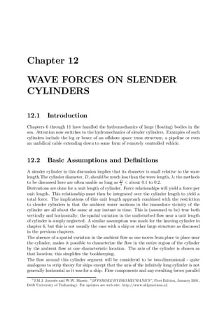
  • 11. 12.4. MORISON EQUATION 12-11 determine the coe¢cients without the use of computers. (Computers - if available at all - were prohibitively expensive when he did his work.) His approach was suitable for hand processing and depended upon the realization that when: u is maximum, u is zero so that at that instant, t1; F (t1) = FD and _ u is maximum, u is zero so that at that instant, t2; F (t2) = FI : _ Figure 12.2 shows a sample of an idealized measurement record. Under each of the above speci…c conditions, equation 12.27 can be re-arranged to yield: 2F CD = at an instant t1 when u = 0 _ ½D ¢ ua jua j 4F CM = at an instant t2 when u = 0 (12.30) ¼ ½ D2 ¢ ! ua The method is simple, but it lacks accuracy because: Figure 12.2: Measured Force and Velocity Record - A small error in the velocity record can cause a signi…cant phase error. Since the
  • 12. 12-12 CHAPTER 12. WAVE FORCES ON SLENDER CYLINDERS curve of F (t) can be steep (especially when determining CD in …gure 12.2), this can cause quite some error in this coe¢cient. The e¤ect on CM is usually smaller. - Information from only two instants in the time record is used to determine the coe¢cients; the rest is thrown away. Morison reduced errors by averaging the coe¢cients over a large number of measure- ments (wave periods). One might try to use this same approach at other time instants in the record. The only di¢culty, however, is that one is then confronted with a single equation (for F at that instant) but with two unknown coe¢cients. This cannot be solved uniquely. A second equation could be created by examining the situation at a second, indepen- dent time instant. A generalization of this would be to use the data pairs at every instant with a least squares …tting technique. This is discussed below, but only after another approach using Fourier series has been presented. 2. Fourier Series Approach An entirely di¤erent method for determining the drag and inertia coe¢cients is based upon the comparison of similar terms in each of two Fourier series: One for the water motion and one for the force. Appendix C summarizes the theory behind Fourier series. Since modern laboratory data records are stored at discrete time steps (instead of as continuous signals), the integrals needed to evaluate the Fourier coe¢cients are replaced by equivalent sums. Looking at this in a bit more detail, the water velocity and acceleration is already in a nice form as given in equation 12.28. A single Fourier series term is su¢cient to schematize this quite exactly. Since the inertia force, FI , is also well behaved, it can be ’captured’ with a single Fourier series term as well. The only remaining problem is the series development of the drag term; this requires the development of a function of form: f (t) = A cos (!t) ¢ j cos (!t)j (12.31) This has been worked out in Appendix C as well. The resulting coe¢cients (given there as well) for the …rst harmonic development of the quadratic drag turn out to be: Fourier Coe¢cient Value Constant, a0 0 Cosine, a1 8 3¼ ¢ A = 0:849 ¢ A Sine, b1 0 As shown in Appendix C, the drag force, dependent upon u juj, develops into a series of odd-numbered harmonics in a Fourier series; only the …rst harmonic terms are used here. Since this has an amplitude of 3¼ times the original signal, one must multiply 8 the …rst order harmonic of the force in phase with the velocity by a factor 38¼ to get the amplitude of the quadratic drag force. Once this has been done, then the determination of C D and CM from the analysis of the compete force signal, F (t) is completely straightforward. Since the inertia force component shows up now in the b1 term of the series development, the results are: 3¼ 4 b CD = ¢ a1 and CM = ¢ 1 2 ½ ! u (12.32) 4½D ¼D a
  • 13. 12.4. MORISON EQUATION 12-13 in which the following amplitudes are found: a1 = velocity-dependent Fourier amplitude (kg/m2) b1 = acceleration-dependent Fourier amplitude (N m) Notice that with this method one has used data from the entire time record in the determination of the Fourier series components and thus for the determination of CD and CM . This should be an improvement over the method used originally by Morison, but on the other hand, it is still only as accurate as the linearization can be. 3. Least Squares Method A third approach treats the basic Morison equation, (12.27) as a computational approximation, F (t; CD; C M )computed , for the measured force record, F (t)measured . One is now faced with only the problem of determining the (linear) unknown coe¢cients, CD and CM . This is done by minimizing some residual di¤erence (or …t criterion) function. The method of least squares uses a residual function of the form: Z T R(CD ; CM ) = [F (t)measured ¡ F (t; CD; CM )computed] 2 dt (12.33) 0 in which T is now the length of the measurement record. Now one only needs to iteratively evaluate equation 12.33 for various values of CD and CM until the residual function, R(CD; C M ) is minimized. If one were to plot this function in three dimensions - with C D and CM on the two orthogonal horizontal axes and R(C D; CM ) on the vertical axis, then one would …nd a sort of ’bowl-shaped’ function. It doesn’t take too much thought to realize that if the shape of the bottom of this ’bowl’ is rather ‡at, then there are many combinations of C D and CM which give about the same R(CD ; CM ) function value. The consequence of this is that it is quite di¢cult to determine the ’best’ C D and CM values exactly in a numerical way. On the other hand, it is theoretically possible to determine the minimum of the @R @R function .R(CD; C M ) by setting both of its partial derivatives, @CD and @CM equal to zero analytically. 4. Weighted Least Squares Method The least squares method, above, uses the entire time record for the determination of CD and CM ; it shares that advantage with the Fourier series approach. On the other hand, one can reason that for o¤shore design purposes, it is more important that the Morison equation predict the force peaks accurately than to be as precise at moments when the force is nearly zero. One way to improve the …tting near the peak forces is to weight the di¤erence found above in equation 12.33 with - for example - the measured or computed force value. Equation 12.33 can then become something like: Z T Rw (CD ; CM ) = [F (t)measured] 2 ¢ [F (t)measured ¡ F (t; C D; CM )computed]2 dt 0 Of course the shape of the residual function - the shape of the ’bowl’ - will now be di¤erent and hopefully steeper and deeper (not so ‡at on its bottom). Even if this
  • 14. 12-14 CHAPTER 12. WAVE FORCES ON SLENDER CYLINDERS is not the case, however, one can expect that a Morison equation …tted in this way will give a more accurate prediction of the force peaks. Note that most any researcher can dream up his own residual or criterion function to use in this approach. Residual values are usually not dimensionless quantities; the absolute (numerical) value of R or Rw (or any other criterion function for that matter) is quite irrelevant; only relative values are of interest. There is certainly no point in comparing them by, for example, comparing values of R with those of Rw . The only important matter is that of …nding the C D and CM associated with the minimum value of the criterion function chosen. 5. Alternative Approach This method illustrates an entirely di¤erent approach to the problem. It was used by Massie some years ago - in an age when digital computers were still slow enough to make numerical integrations a cumbersome process. Instead, integrations were carried out using an analog computer; this could carry out these nearly instantly and painlessly. The analog computer was coupled to a digital computer which read the results of the integration and adjusted the coe¢cients accordingly for the next try. Such a computer was called a hybrid computer. The solution was based upon the following approach: First the Morison equation, 12.27, was written in the following form: F (t) = +P ¢ CM ¢ u(t) + Q ¢ C D ¢ u(t) ¢ ju(t)j _ (12.34) in which P and Q are simply known constants. Both u(t) and F (t) had been measured and were known functions of time. The special approach feature was to re-arrange equation 12.34 by solving it for u(t)_ yielding: 1 1 Q CD u(t) = ¢ _ F (t) ¡ ¢ ¢ u(t) ¢ ju(t)j (12.35) P CM P CM Equation 12.35 is, thus, a …rst order nonlinear ordinary di¤erential equation in u(t) which has a given solution - the measured u(t) - but two unknown coe¢cients: 1=C M and CD =C M . Values for the unknown coe¢cients were set by the digital portion of the computer; the analog portion integrated the di¤erential equation to generate a computed uc(t) and simultaneously subtract it from the measured u(t) to give a residual which was also integrated over a time period in the analog portion. This integral value was the residual function to be minimized using a numerical routine in the attached digital computer. Notice that the criterion function is now based upon the velocity record instead of the force record! Of course, various weighting functions were tried as well. Five di¤erent methods of determining CD and CM (or C a) coe¢cient values from a single time record of water motion and force have been presented here. The frustrating result of all this is that if one time record were to be analyzed with each of these methods, each method would yield a di¤erent pair of CD and C M coe¢cient values! One can conclude - correctly! - from this that it is impossible to determine exact values for these coe¢cients; a tolerance of several percent is the very best one can expect. It can also happen that one …nds widely varying values for CD or CM when comparing results from two di¤erent time series with very similar test conditions. This can happen
  • 15. 12.4. MORISON EQUATION 12-15 with the drag coe¢cient, for example, when F (t) is inertia dominated as it is called. Inertia dominated implies that the drag force is relatively unimportant so that since the rest of the information used to compute FD is relatively small, this small value times any coe¢cient value is still small. The converse is obviously also true: The inertia coe¢cient value is unimportant if the force is drag dominated. More about the conditions which can lead to this will be presented below in the discussion of the relative amplitudes of the drag and inertia forces. Cylinder Roughness All of the above discussion has been for a smooth-surfaced (vertical) cylinder. Since o¤shore structures accumulate marine growth very easily in at least the warmer seas, this modi…es the hydrodynamic force computation in two ways: First, the cylinder can become larger - a marine growth layer of 10 centimeters thickness will increase the cylinder’s diameter by 0.2 meters. This can be accounted for quite easily in the Morison equation. The second in‡uence is that the roughness will in‡uence the boundary layer and vortex separation near the cylinder. The drag and inertia coe¢cient values are generally adjusted to account for this as will be seen later in this chapter. Presentation Parameters Now that C D and CM values have been found for a given ‡ow condition, it is logical to want to present these results via a graph in which CD and CM are the dependent variables plotted along the vertical axis. One must still choose a proper independent variable for the horizontal axis, however. This would (ideally) include information on the wave (H; T or something related to these), the ‡uid (½; º for example) and the cylinder (D is most obvious choice for this, but it might include the roughness, too). Several possibilities for making dimensionless combinations are discussed in this section. 1. Reynolds number The Reynolds number for a constant current was given in chapter 4. This is modi…ed here for unsteady ‡ow by replacing the constant current by the amplitude of the oscillation velocity yielding: ua ¢ D Rn = (12.36) º in which: Rn = Reynolds number (-) ua = ‡ow velocity amplitude (m/s) D = cylinder diameter (m) º = kinematic viscosity (m2 /s) 2. Froude Number The Froude number can now be expressed using the velocity amplitude as well as: ua Fn = p (12.37) g¢D in which: F n = Froude number (-) g = acceleration of gravity (m/s2 )
  • 16. 12-16 CHAPTER 12. WAVE FORCES ON SLENDER CYLINDERS The Froude number is associated primarily with free surface e¤ects while wave forces can be exerted on cylinder elements which are so far below the sea surface that no surface disturbance is generated. The Froude number is not really suitable for the present purpose, therefore. 3. Keulegan Carpenter Number [Keulegan and Carpenter, 1958] determined C D and CM values for various cylinders in an oscillating ‡ow. They discovered that their data could be plotted reasonably as a function of the dimensionless Keulegan Carpenter number: ¯ ¯ ¯ ¯ ¯KC = ua ¢ T ¯ (12.38) ¯ D ¯ in which: KC = Keulegan Carpenter number (-) T = oscillating ‡ow period (s) This number can be de…ned in alternate ways. In a sinusoidal wave, ua = ! ¢ xa , in which xa is the (horizontal) water displacement amplitude. A bit of substitution then yields: water displacement amplitude x KC = 2¼ ¢ = 2¼ a (12.39) cylinder diameter D which is very likely an important characteristic for the wake formation in the ‡ow as well. In deep water, the water displacement amplitude xa at the sea surface is identical to the wave amplitude. This allows still another form in this speci…c situation: H ³ KC = ¼ ¢ = 2¼ ¢ a (deep water only) (12.40) D D 4. Iversen Modulus Even before Keulegan and Carpenter did their work, [Iversen and Balent, 1951] sug- gested: ua ¢ D _ Iv = (12.41) u2 a in which: Iv = Iversen modulus (-) ua = ‡ow acceleration amplitude (m/s2) _ Knowing that in a sinusoidal wave ua = 2¼ ua ; and by doing a bit of algebra, one can _ T discover that: 2¼ Iv = (12.42) KC KC is more convenient to use in practice, however. 5. Sarpkaya Beta [Sarpkaya and Isaacson, 1981] carried out numerous experiments using a U-tube to generate an oscillating ‡ow. He found that the ratio: D2 ¯= (12.43) º¢T
  • 17. 12.4. MORISON EQUATION 12-17 was convenient for plotting his data. Just as with the Iversen modulus, this can be ’processed’ a bit to reveal that: Rn ¯= (12.44) KC so that this is not really anything new, either. 6. Dimensionless Roughness Cylinder roughness is generally made dimensionless by dividing it by the diameter, yielding: " roughness height = (12.45) D cylinder diameter The Keulegan Carpenter number has survived as the most realistic and useful primary independent parameter for plotting CD and CM : This is sometimes augmented by using Rn , ¯ or D to label speci…c curves, thus introducing additional independent information. " 12.4.3 Typical Coe¢cient Values Hundreds (at least) of researchers have conducted laboratory tests to determine CD and CM coe¢cients in one way or another and often for very speci…c situations. In many cases, their objective and/or experimental set-up limited their range of test conditions so that their results are quite restricted, too. Typical results are listed in this section. The results of Sarpkaya’s experiments with smooth cylinders in U-tubes are presented as graphs of the coe¢cients CD and CM as functions of ¯ and K C: Note that in …gure 12.3 the horizontal (K C) axis is logarithmic. Individual curves on each graph are labeled with appropriate values of ¯. [Clauss, 1992] for example suggests drag and inertia coe¢cient values given in the following table: Rn < 105 Rn > 105 CD CM CD CM KC < 10 1:2 2:0 0:6 2:0 > 10 1:2 1:5 0:6 1:5 Morison Coe¢cients Suggested by [Clauss, 1992] Various design codes or rules also specify (or suggest) appropriate values for CD and CM . Those published by [DetNorskeVeritas, 1989] or the American Petroleum Institute (API) are the most widely accepted; the DNV suggestions for design purposes are shown in …gure 12.4. The API as well as the SNAME have the simplest approach as listed in the table below:
  • 18. 12-18 CHAPTER 12. WAVE FORCES ON SLENDER CYLINDERS Figure 12.3: Typical Laboratory Measurement Results from Sarpkaya
  • 19. 12.4. MORISON EQUATION 12-19 Figure 12.4: Suggested Drag and Inertia Coe¢cient Values from DNV
  • 20. 12-20 CHAPTER 12. WAVE FORCES ON SLENDER CYLINDERS Smooth Rough CD CM CD CM API 0:65 1:6 1:05 1:2 SNAME 0:65 2:0 1:0 1:8 The following observations can be made from the above information: - For low values of K C, the inertia coe¢cient C M is almost equal to its theoretical value of 2 - at least if the K C value is used as a selection parameter. Also, one can notice that the drag coe¢cient CD generally increases or stays rather constant till a value of KC near 10 is reached. - One sees as well from …gure 12.3 that the CD value gets lower as ¯ increases. This is just the opposite of the trend observed with CM : - Comparison of Sarpkaya’s curves (…gure 12.3) with those from DNV (…gure 12.4) show that there can be quite some discrepancy in the value of CD or CM to choose. - The DNV curves (…gure 12.4) as well as the other design and assessment codes include roughness - that can easily result from marine growth, especially near the sea surface. The roughness in …gure 12.4 is an D ratio. ² - The API and SNAME recommendations seem rather simple in that they neglect the KC number; Clauss adds that e¤ect, but in a more simple way that suggested by DNV. Comparisons Examination and comparison of the various drag and inertia coe¢cient values presented above shows that there is little agreement on exact values. This is true for smooth cylinder values and even more so when a rough cylinder is involved. Di¤erences of up to roughly 40% can be found when comparing the drag or inertia coe¢cients suggested by the various sources for a speci…c ‡ow situation. This direct comparison of coe¢cient values can be misleading, however. In some cases a low drag coe¢cient value can be at least partially compensated by a larger inertia coe¢cient. After choosing a typical cylinder diameter and wave conditions, one can select appropriate coe¢cients from each of the sources and compute the actual maximum force per unit length upon which to base a comparison. Such an exercise can still lead to di¤erences of up to about 30%. Luckily for survival design of o¤shore structures, the di¤erences found for extreme wave conditions are generally less than this! Even this comparison need not be correct. The ’purest’ approach is to select a typical structure, and place it (in one’s mind) at a given location in the sea. Given this, one should follow the entire procedure (given in each particular design or analysis code) to select wave and current conditions and to translate these into forces on that structure. These resulting forces should be compared. Carrying out such a comparison operation is beyond the scope of this text, however. One additional discovery that one will make when computing forces under …eld conditions is that Sarpkaya’s data is a bit restricted for this. Indeed, the Reynolds numbers - needed for his ¯ parameter - are much too low in nearly all laboratory situations.
  • 21. 12.4. MORISON EQUATION 12-21 12.4.4 Inertia or Drag Dominance Now that CD and CM values have been presented, one should further re‡ect upon their use and importance. The Keulegan Carpenter number can be a very important parameter for this. Indeed, it can be used as an indication of the relative importance of drag versus inertia forces in a particular situation. To prove this, one must work out the ratio of the amplitudes of the drag and inertia forces. The 90± phase di¤erence between the force components is completely neglected now; only the force component amplitudes are compared. 1 Fdraga ½ CD D ua juaj 2 = ¼ Finertiaa ½ CM D2 ! ua 4 2 CD jua j = (12.46) ¼ CM D ! Note that the maximum value of juaj is the same as that of ua . Since ! = 2¼=T ; then this can be reduced a bit to: Fdraga 1 CD ua ¢ T = ¢ ¢ Finertiaa ¼2 CM D 1 CD = ¢ ¢ KC (12.47) ¼2 CM Since 1=¼ 2 ¼ 1=10 and the value of CD is often a bit more than half the CM value, the two force component amplitudes are about equal when K C is in the range of roughly 15 to 20: Remembering the earlier de…nition of KC from equation 12.39: 2¼ xa KC = (12.48) D then this means that xa=D will be about 3; this is big enough to generate a very respectable set of vortices. The Morison equation includes a nonlinear (quadratic drag) term which is 90± out of phase with the inertia force. Many o¤shore engineers want to avoid using the entire Morison equation (and the quadratic drag computation especially) unless it is absolutely necessary. It would be convenient to have a simple way to justify neglecting either the drag term or the inertia term in that equation. The Keulegan Carpenter number is an excellent help with this: ² For low values of K C (K C < 3), the inertia force is dominant. The ‡ow ’does not travel far enough’ relative to the cylinder diameter to generate much of a boundary layer not to mention vortices; potential ‡ow theory is still applicable. Drag can simply be neglected. ² For the next range until drag becomes signi…cant (3 < KC < 15); one will often linearize the drag as has been explained earlier in this chapter. ² There is a range of K C (15 < KC < 45) in which one cannot really avoid using the full Morison equation with its nonlinear drag.
  • 22. 12-22 CHAPTER 12. WAVE FORCES ON SLENDER CYLINDERS ² For high values of KC (KC > 45), the drag force is dominant. The vortex shedding frequency becomes high compared to the wave frequency so the ‡ow tends to behave more and more like a uniform ‡ow. Inertia can be neglected. Indeed, the limit K C ! 1 corresponds to a constant current. 12.5 Forces on A Fixed Cylinder in Various Flows This section describes the forces acting on a …xed cylinder in currents and/or waves. While parts of it may seem like repetition of earlier work, its objective is to clarify the underlying principles. 12.5.1 Current Alone A …xed cylinder in a current alone will experience only a quadratic drag force (per unit length) as already indicated in chapter 4. This force is assumed to be caused by the ‡ow component: Up = U sin · acting perpendicular to the cylinder axis so that the force can be expressed as: 1 Fc = ½ U 2 D CD sin2 · (12.49) 2 In these equations: U = Total velocity vector (m/s) Up = Perpendicular velocity component (m/s) CD = Drag coe¢cient for constant current (-) · = Cone angle between the velocity vector, U; and the cylinder axis. Fc = Current force per unit cylinder length (N/m) See …gure 12.5 for a sketch showing the cone angle. The force, Fc ; will act in the direction of Up of course; this is perpendicular to the cylinder axis and in the plane de…ned by the cylinder axis and the approaching velocity vector, U: Note that only the so-called cone angle, ·; is important in this computation. This is su¢cient to describe the orientation of the cylinder relative to the current vector. It makes no di¤erence whether the cylinder is in a vertical, horizontal or any other plane; it is only the angle between the cylinder axis and total velocity vector which is important. (This will be generalized to include inertia forces in waves below.) 12.5.2 Waves Alone The time dependent ‡ow associated with waves requires the inclusion of inertia force com- ponents into a force computation. Indeed, the basic Morison equation - derived for a unit length of a …xed, vertical cylinder in waves is re-stated here for reference: ¯ ¯ ¯ 1 1 ¯ ¯F = ¼ ½ D M u(t) + ½ C D D u(t) ju(t)j¯ 2 C _ (12.50) ¯ 4 2 ¯
  • 23. 12.5. FORCES ON A FIXED CYLINDER IN VARIOUS FLOWS 12-23 Figure 12.5: Cone Angle De…nition in which: F = Force per unit length of cylinder (N/m) D = Cylinder diameter (m) u(t) = Horizontal velocity component (m/s) u(t) = _ Horizontal acceleration component (m/s2) How can this be generalized in the light of the above information on currents for a cylinder having a non-vertical orientation? The following steps are suggested in which the inertia force and the drag force are considered to be separate entities until the end. The following sequence of steps must be carried out sequentially and at each time step for which results are desired:: 1. Determine the instantaneous water kinematics: velocity and acceleration (magnitudes as well as directions) in a …xed x; y; z axis system. Relate their phase to that of a reference such as the wave pro…le. 2. Knowing the cylinder axis orientation (in that same x; y; z axis system), determine the instantaneous cone angles, ·I and ·D for the acceleration and velocity respectively. 3. Determine the instantaneous perpendicular components of acceleration and velocity - up and up - as well as their directions. Use the results from the two previous steps _ to do this. These two vectors will not generally be co-linear; they are both in the plane perpendicular to the cylinder axis, however. 4. Evaluate the inertia and drag force components at each instant. Don’t forget that the drag is quadratic! The direction of each force component will correspond to that of its associated kinematics found in the previous step. 5. If the force on an entire member is needed, then now is the time to integrate these separate force components over the length of the member in order to determine each resultant at that time. The member support forces - and thus the equivalent loads to be applied at the structure nodes - can be found by treating each member as a simple beam.
  • 24. 12-24 CHAPTER 12. WAVE FORCES ON SLENDER CYLINDERS 6. Since the inertia and drag force components are not generally colinear, they can be combined (if desired) via vector addition to yield the resulting force magnitude and its direction (still in a plane perpendicular to the cylinder axis). This step is not absolutely necessary for the computation of resulting forces on a large structure, however. Note that these …ve or six steps must be repeated at each instant in time. These steps are not di¢cult in principle, but very careful bookkeeping is essential! In many simple cases, each of the quantities needed for this methodology will be express- ible in terms of nicely behaved and convenient functions so that the resulting force can be described as one or another continuous time function. On the other hand, if the wave is irregular and thus composed of many frequency and direction components, then the neces- sary bookkeeping becomes too cumbersome for a hand calculation. The only requirement for the force computation is that the water acceleration and velocity be known at any time. Special Orientations One can check his or her understanding of the above by evaluating the forces acting on two special cases of a horizontal cylinder in a regular wave. These are in addition to the vertical cylinder used during the Morison equation derivation. If the horizontal cylinder segment is oriented with its axis parallel to the direction of wave propagation (and thus perpendicular to the wave crests), then it will experience a vertical force which has a time trace which looks much like that for a vertical cylinder - see …gure 12.2. This force record will be shifted 90± in phase relative to a similar record for a vertical cylinder, however. The relative phases of the resulting drag and inertial force components on consecutive segments of the cylinder will correspond - with some constant shift - to that of the wave pro…le on the sea surface. The second case has the horizontal cylinder turned parallel to the wave crests (and thus perpendicular to the direction of wave propagation). If the cylinder is situated in a deep water wave (in which the horizontal and vertical kinematic components have the same magnitudes) then one will …nd a resultant force of constant magnitude which sweeps around the cylinder once per wave period. It may seem strange, but the horizontal component of this force will have a purely sinusoidal form (except for a possible phase shift) independent of the fact that quadratic drag is involved. Force components on consecutive segments of this cylinder will have identical phases in this case as compared to the previous one. 12.5.3 Currents plus Waves It is generally accepted practice to vectorially superpose the current velocity on the velocity resulting from the waves before calculating the drag force. In a general case the wave and current directions will not be co-linear making a vector sum necessary. Once this has been carried out, however, one simply has to use the sequential steps given above to determine the resulting force at any instant. Why is it not acceptable to compute the wave force and the current force separately? The current has no e¤ect at all on the ‡ow accelerations so that the inertia force is unchanged by the current. The di¢culty lies with the quadratic drag force. Since: Up + u2 < (Up + up )2 2 p (12.51)
  • 25. 12.6. FORCES ON AN OSCILLATING CYLINDER IN VARIOUS FLOWS 12-25 then a segregated treatment of the current drag and wave drag - which are superposed only at the end of the computation - will lead to an underestimation of the forces involved. 12.6 Forces on An Oscillating Cylinder in Various Flows Now that the hydrodynamic interaction of a …xed cylinder in a variety of ‡ows has been explained, it is appropriate to discuss the hydrodynamic interaction of a moving cylinder - again in a variety of ‡ow conditions. A distinction will now have to be made between the (external) force exerted by the cylinder on the surrounding water and the (internal, structural) force needed to cause the cylinder (segment) to oscillate. In general, the internal force will often be one that is measured - especially in a laboratory setting. This force includes the external hydrodynamic force but also includes a force needed to accelerate the cylinder itself. Also, one should remember that the hydrodynamic interaction force components will generally be in a direction opposite to the actual velocity and acceleration of the cylinder. 12.6.1 Still Water As indicated much earlier in this chapter, the Froude-Krilov force will be absent since there are no ambient pressure gradients in water which is at rest. The inertia force will be associated with a Ca value and there will be a drag force - associated with CD as well. Analogous to the assumption made for a …xed cylinder, these forces will be associated with the cylinder kinematics components (velocity and acceleration) which are perpendicular to the cylinder’s axis. The …ve steps used for determining the forces on a …xed cylinder can used here too, albeit that the kinematics now is that of the cylinder instead of the water. 12.6.2 Current Alone This interaction situation has already been discussed to some extent in chapter 4. One should remember that the direction of cylinder oscillation and the current direction may be quite di¤erent. Indeed, a vortex-induced vibration usually has its largest component more or less perpendicular to the current direction. This results from the lift force - the most important dynamic force in this ‡ow situation - which was discussed in chapter 4. The drag component of the hydrodynamic interaction was quite well described in section 6 of that chapter too; there is no need to repeat that here. Inertia forces will - in principle - now be present, too. They will be associated with a Ca value since there is still no ambient time-dependent pressure gradient. These forces will be opposite to the acceleration component which results exclusively from the cylinder oscillation in this case. In many realistic cases the approaching ‡ow velocity will be considerably larger than the cylinder’s oscillation velocity. Also, since most oscillating cylinders are rather slender (an umbilical cable to a ROV is an excellent example) the K C number will be large so that inertia forces will be small anyway. In many practical situations, then, one considers only a drag force as if it were exerted on a …xed cylinder. The drag coe¢cient is sometimes a bit larger to account for the wider wake resulting from the cylinder oscillation.
  • 26. 12-26 CHAPTER 12. WAVE FORCES ON SLENDER CYLINDERS 12.6.3 Waves Alone The inertia and drag forces are treated entirely separately here for clarity. Inertia Forces Waves will contribute both a Froude-Krilov force (from the ambient, time-dependent pres- sure gradient) as well as a disturbance force from the encounter with the solid cylinder. The cylinder oscillation, on the other hand, plays no role in the Froude-Krilov force but it does contribute to the disturbance term. (It is implicitly assumed here that the motion of the cylinder is small relative to the wave length so that no phase changes result from this displacement. It is hard to conceive of a practical situation for which this assumption does not hold.) When one keeps in mind that the direction of cylinder oscillation need not coincide with the wave direction, then careful bookkeeping is called for. One …nds the following inertia terms in the equation of motion: M X(t) ¯ CM MD up (t) ¡ Ca MD X(t) Ä _ Ä (12.52) in which: M = Mass of the cylinder segment (kg/m) MD = Displaced water mass = ¼ D2½ (kg/m) 4 up(t) = _ Perpendicular acceleration component from the waves (m/s2) Ä X(t) = Cylinder acceleration (m/s2) The symbol ¯ has been used to segregate terms from the left hand side of the full equation of motion from those on the right. Since only selected terms are included, true equality cannot be guaranteed. The above relationship can be re-arranged by splitting the wave force term into its two components so that: M X(t) ¯ 1 MD up(t) + Ca MD up (t) ¡ Ca MD X(t) Ä _ _ Ä (12.53) If the cylinder acceleration corresponds exactly - in both magnitude and direction - to that of the waves, then the last two terms in this latter equation cancel. This is logical; there is then no disturbance at all and only the Froude-Krilov force remains. In the more general case, all three hydrodynamic force components in equation 12.53 will be present. It is often convenient to move all the force terms involving the cylinder motion to the left hand side of the equation so that it becomes: (M + C a MD ) X(t) ¯ C M M D up(t) Ä _ (12.54) This isolates the (unknown) cylinder motion on the left hand side of the equation and places the time-dependent external exciting force on the right. This right hand side can be evaluated (without knowing the cylinder motion) as a pure time function before the di¤erential equation of the cylinder motion is evaluated. Drag Forces Drag forces result from the ‡ow disturbance and wake near the cylinder. Two quite dif- ferent approaches to the description of hydrodynamic drag are used. They are discussed separately here.
  • 27. 12.6. FORCES ON AN OSCILLATING CYLINDER IN VARIOUS FLOWS 12-27 Relative Velocity Approach It is reasonably simple to postulate that this wake de- pends upon the motion of the water relative to the (moving) cylinder - the relative velocity: _ u ¡ X. It results in a drag force proportional to the square of this relative velocity so that one …nds the following velocity-dependent terms in the equation of motion: ¯ ¯ 1 c X(t) ¯ ½ CD D (up(t) ¡ X (t)) ¯ up (t) ¡ X(t)¯ _ _ ¯ _ ¯ (12.55) 2 in which: c = Material damping coe¢cient (N ¢ s/m) up(t) = Time-dependent perpendicular water velocity (m/s) _ X(t) = Time-dependent cylinder velocity (m/s) The linear damping term on the left hand side of relation 12.55 involves the internal material damping of the cylinder itself. This has nothing to do with hydrodynamic interaction which is concentrated on the right hand side of the relation. Notice that the quadratic nature of the drag force makes it impossible to segregate the (unknown) cylinder velocity from the ambient water velocity when computing this exciting force in this way. It is not possible compute this time-dependent excitation force component from the water motion independent of the (also time-dependent) dynamic response of the cylinder. This requires simultaneous step-by-step solution of the di¤erential equation in the time domain. Additionally, an extra iterative loop must be included within each _ time step in order to successively approximate values of X until the entire di¤erential equation is satis…ed at each time step. This makes such time-domain computations rather time-consuming - even with modern computers. Absolute Velocity Approach A strict interpretation of this approach uses the princi- ples of superposition in much the same way as they are used in the hydrodynamics of larger structures. The forces resulting from the combined motion of the cylinder in waves plus currents is treated as if it were made up of two independent phenomena: A force caused by the waves plus current on a stationary cylinder proportional to up jupj plus a separate _ force exerted on a cylinder oscillating in still water which is proportional to X 2. This _ approach inherently ’fails to see’ the cross product (¡2 up X) term included automatically in the relative velocity approach. Further, since the motions of the cylinder will usually be considerably less that those of the surrounding water, the largest contribution to the (external) drag force will therefore come from the up jup j term. This can be left alone on the right hand side of the equation; it can be evaluated quite easily. The relatively _ small X 2 term can be linearized and moved to the left hand side of the equation of mo- tion. This linearized drag force now behaves in the same way as a linear damping; it has the same e¤ect as increasing the structural damping which one normally includes in such computations. Alternatively, one can use an even more pragmatic approach by noticing that the latter two terms of the time-dependent product in the expanded version of relation 12.55 involving u are both smaller than the …rst term and are often of opposite sign; their combined e¤ect will be small. One now linearizes this small e¤ect and associates it entirely with the _ cylinder velocity, X; and treats it as above. Even if the structure’s damping coe¢cient is not modi…ed, the result of either of these approaches can be that the full di¤erential equation of motion for the cylinder has been
  • 28. 12-28 CHAPTER 12. WAVE FORCES ON SLENDER CYLINDERS linearized and that the wave-caused excitation force has been isolated on its right hand side. Each motion is treated as if it is in a …xed axis system. It is for this reason that this approach is often referred to as the absolute motion approach. Comparison Designers tend to be conservative in practice. As a result of this, they tend not to modify the linearized damping when using the absolute motion approach. Since a dynamic system with a lower damping will often have a larger response, the absolute motion approach most usually leads to higher predicted structural responses (internal stresses or even displacements, for example) than does the relative velocity approach. This is indeed a strong motivation to use the absolute velocity approach when evaluating the performance of a proposed design. The additional advantage of having a straightforward and simple computational procedure comes as an added bonus. 12.6.4 Currents Plus Waves Just as with the …xed cylinder, all hydrodynamic velocity components are generally super- posed before starting a force computation. Once this has been done, the further treatment is identical to that for an oscillating cylinder in waves alone as discussed above. 12.7 Force Integration over A Structure The discussion above has concentrated on the forces on a unit length of cylinder or at least no more than a single member of a large truss structure. It is now time to integrate these forces over the length of the cylinder in order to determine loads which are relevant for structural analysis and design evaluation. Since many space truss analysis computer programs work with externally applied joint loads, the goal should be to transform the distributed hydrodynamic load on each member of the structure to equivalent concentrated loads at the structure’s nodes. Generally, this procedure will have to be followed during a whole series of discrete time steps in order to generate time-dependent loadings which may be needed for a dynamic analysis. Many computer programs for this purpose work somewhat as follows: As preparation, ² The nodes of the structure are numbered sequentially. ² Each node is assigned a set of X; Y; Z coordinates corresponding to the intersection point of the member axes at that joint. (Any member eccentricity at the joint is neglected in the hydromechanics.) ² Each member is speci…ed by its diameter and the numbers of the two nodes which it joins. Each member’s geometric position and length is now de…ned. Once this has been completed the following steps will be carried out for the dynamic loads at each desired time step: 1. The water kinematics - both combined velocities and accelerations - will be computed at each node location. It makes no di¤erence now whether the waves are regular or irregular; there can even be directional spreading or additional currents involved.
  • 29. 12.7. FORCE INTEGRATION OVER A STRUCTURE 12-29 The result in all cases is known water kinematics at each node and at every chosen time. 2. If a dynamic calculation is included, and relative velocity drag is used, then the structure’s velocity and acceleration at each node will have to be estimated as well. This is usually done by incrementally integrating the structure’s equations of motion by working from the previous time step. 3. The results of the above two steps along with the known geometry allow the com- putation of the force per unit length (for inertia and drag forces separately) at each end of each member. These load intensities will have to be computed separately for each member and at each of its end joints. 4. Most programs now consider each member to be a simple beam carrying a distributed load which is assumed to vary linearly from one end to the other. Note that both the intensity of the loading as well as the vector direction of the loading (about the axis of the cylinder) may vary along its length. (Direction variation can be present when the waves and current are not co-linear. It is also present when wave directional spreading is involved.) 5. Basic mechanics yields the two reaction force components (relative to each member’s axis!) at each of its ends. 6. It is now only a matter of bookkeeping to transform these individual member reaction forces into equivalent X; Y; Z force components at each joint. 7. The above X; Y; Z components at each joint are summed to determine the total equivalent applied dynamic load at that joint at the chosen moment. This is the desired result. 8. If relative velocity hydrodynamics is being used this result must be checked. The equations of motion of the structure must be integrated now to determine its new velocity and acceleration at the end of the time step. If these values do no correspond (within a chosen tolerance) with those estimated in step 2, then the above steps must be repeated for another iteration cycle - within this same time step - until the estimated and computed values appropriately coincide. It is the extra iteration loop discussed in the last of the above steps that makes the rel- ative velocity approach to hydromechanics so computationally ine¢cient relative to other approaches. Constant static loads, such as member weight and buoyant forces, can be included in the above computation, but can be computed more e¢ciently separately before starting on the dynamic computations. The computation principle is analogous to that for the dynamic loads, by the way.
  • 30. 12-30 CHAPTER 12. WAVE FORCES ON SLENDER CYLINDERS .
  • 31. Chapter 13 SURVIVAL LOADS ON TOWER STRUCTURES 13.1 Introduction Chapter 12 has discussed how to compute the hydrodynamic forces on an element (of unit length) of a single (slender) cylinder; a simpli…ed means of estimating the largest hydrodynamic forces on an o¤shore tower structure will be handled in this chapter. Figure 13.1 shows an isometric drawing of one of the larger o¤shore structures. The annotations in that …gure will become clear in the course of this chapter. Some refer to such a structure as a space frame, others see it as a space truss, some just call it a tower. The terms ’frame’ and ’truss’ have quite di¤erent structural engineering connotations which are not at all relevant to the hydrodynamic discussion in this chapter. Another structural distinction is that a jacket is supported from the top by piles driven through its legs while a tower is generally supported from below by piles driven through sleeves - usually at the sea bed. This distinction is also irrelevant for the hydrodynamics being discussed here; the term tower will be used more generically in this chapter to refer to any three-dimensional structure made up from slender elements. Imagine the bookkeeping and computational e¤ort needed to compute the total hydro- dynamic forces on the structure shown in …gure 13.1 if this were to be done using the elemental methods of chapter 12. Such a rigorous computation for a ’real’ tower structure (with all its members: chords, braces, risers, etc.) is a very cumbersome undertaking, indeed. Many design engineers have no need for the computational accuracy suggested by a detailed schematization of such a complex o¤shore structure - at least not during the preliminary design phase. Instead, one more often needs a fast method of making a rough and preferably conservative estimate of the hydrodynamic forces on a complex o¤shore structure. Such a method can serve two purposes: Give a rough estimate for preliminary design or assure that a detailed model is not making a major error. The objective of this chapter is to outline a ’quick and dirty’ method to estimate the horizontal loads on a tower structure. These loads generally yield the largest overall bending moments in the structure and thus axial leg forces as well as the largest horizontal shear forces. These forces and moments are also important for the foundation design. Maximum in-service bracing loads result from 0 J.M.J. Journée and W.W. Massie, ”OFFSHORE HYDROMECHANICS”, First Edition, January 2001, Delft University of Technology. For updates see web site: http://www.shipmotions.nl.
  • 32. 13-2 CHAPTER 13. SURVIVAL LOADS ON TOWER STRUCTURES Figure 13.1: Typical Larger O¤shore Tower Structure
  • 33. 13.2. ENVIRONMENTAL CONDITIONS TO CHOOSE 13-3 the horizontal wave and current loads as well. 13.1.1 Method Requirements The results obtained with any approximation need not be exact - especially if one can reasonably predict whether the ’real’ loads will be smaller (or larger) than the estimates. Generally - and for preliminary design in particular - it is handy if the hydrodynamic loads resulting from the approximation are larger than those which would follow from a more sophisticated analysis. When a preliminary design is based upon loads which are overestimated, it is most likely that the resulting structure will be ’over-designed’; it will be a bit too big, or heavy, or strong and thus probably too costly. Given this fact, then one would not expect the costs of a structure resulting from a more detailed design to come out too high. Said in another way, if the preliminary design survives an economic analysis, then the …nal design has a good chance of surviving this too - at least to the extent that its total cost is determined by hydrodynamics. An additional factor in practice is that topsides tend to become heavier (as more equipment is added) rather than lighter during the design process. (Whether one likes it or not, topside structures usually tend to get larger and heavier in the course of their detailed design. This can result from equipment or throughput changes as well as from modi…ed environmental or safety requirements.) To the extent that the tower design is dictated by topside weight (if the water is not all that deep depending upon the sea conditions), a bit of initial tower overdesign can prove to be handy during the later, more detailed design analysis phase. The objective of this chapter, therefore, is to come up with a computational procedure to conservatively predict the hydrodynamic forces on a complex o¤shore tower structure. 13.1.2 Analysis Steps Any hydrodynamic analysis of an o¤shore structure involves the following steps: 1. Selection of environmental conditions (raw data). 2. Schematization of the ambient hydrodynamics. 3. Schematization of the structure. 4. Computation of resulting (survival) forces and overturning moments. These steps will be followed in the remainder of this chapter. 13.2 Environmental Conditions to Choose Since one is looking for a maximum external load condition, it is common that this will be caused by a maximum environmental input condition. (A signi…cant dynamic response - which via resonance can lead to enhanced internal loads - can lead to internal response maxima (leg forces, for example) which are caused by more moderate external sea condi- tions. This is not considered here; it is not that common with tower structures, anyway.) All of this means that extreme wind, wave and current conditions should be chosen for this …rst design. Each of these involves at least two independent variables: Speed (in some form) and direction. All of environmental inputs can be represented as vectors, but their scalar magnitudes and directions are discussed separately here.
  • 34. 13-4 CHAPTER 13. SURVIVAL LOADS ON TOWER STRUCTURES Wind Speed Wind loads on o¤shore structures often play a relatively minor role in comparison to the hydrodynamic loads. For an o¤shore wind turbine, even - on which one would expect to have a relatively high wind load - the wind load is seldom greater than the combined wave and current load unless the structure is placed in water somewhat less than about 20 meters deep (in the North Sea). This implies that the selection of design wind conditions is often not all that important. When one does want to estimate wind loads, a maximum one-minute wind gust is often chosen. This wind speed is usually measured at a ’standard’ elevation of 10 meters above the sea surface. Current Speed Maximum current speeds are usually chosen for survival design purposes as well. One could select a speed corresponding to a maximum spring tide current, for example. In some cases a velocity pro…le giving the current as a function of depth will be available, too. If not, it is of course conservative to assume that the maximum current acts over the entire depth. Wave Height and Period One should choose wave height and period values such that a maximum wave force or overturning moment is obtained. A high wave is obviously needed. If one assumes that the worst part of a storm will have a duration of about 3 to 6 hours and that an extreme wave - if seen as a single wave - will have a period of in the order of 15 to 20 seconds, then one can expect an exposure to something in the order of 1000 waves during the peak of the storm. The highest wave in a series of 1000 would have a chance of exceedance of 1000 : Substituting this in a Rayleigh wave height distribution yield a design wave height of 1 1:86 times the design signi…cant wave height chosen. (If one works out these limits more exactly, one should expect something more than 540 waves and less than 1440 of them; 1 1 one thousand is pretty close to the average - by chance. If 540 and 1440 are used instead, the wave height ratio is in the range 1.77 to 1.91; this makes no more than 5% di¤erence.) Selecting the shortest wave period consistent with the chosen wave height will yield max- imum water velocities and accelerations - at least near the water surface. On the other hand, the hydrodynamics of waves with shorter periods ’die out’ faster at deeper locations; a proper balance must be found between these two requirements. Wave breaking will, of course, put a lower limit on the wave period for a given wave height; a very high and very short wave will break so that one should also check any chosen combination of these to be sure that the wave is not broken. The necessary relationships (for deep water and a quick estimate) include: H 1 ¸ = 1:56 ¢ T 2 and < (13.1) ¸ 7 in which ¸ is the wave length (m), H is the wave height (m) and T is the wave period (s). The above relations - which come directly from regular wave theory of chapter 5 - are less dependable for larger and irregular waves at sea, however. Since H will generally be rather large, ¸ will not be small, either. The signi…cance of this will show up below.
  • 35. 13.2. ENVIRONMENTAL CONDITIONS TO CHOOSE 13-5 Figure 13.2: Schematic Plan of Tower and Approaching Wave Crests Wind, Current and Wave Directions In general, each of these independent physical phenomena will have its own direction, independent - at least to some extent - from that of others. This is most obvious for the relation between the tidal current direction and the wave direction. These seldom have much correlation. The wind direction and the wave direction - in a major storm at least - is usually rather well (but not perfectly) correlated of course. The conservative choice (which is easy to work with too!) is to simply assume that all three of these phenomena are colinear; they all come from the same direction. Be sure to keep the direction bookkeeping correct. The wind direction is speci…ed usually as the direction from which it comes, while a current direction is most commonly stated as the direction to which it goes. It sounds inconsistent, but a northwest wind and southeast current go in the same vector direction. An independent direction consideration involves the orientation of the structure (about its vertical axis) relative to the environmental conditions. Consider a simpli…ed situation as shown in plan in …gure 13.2. The solid circles represent the legs of the tower as seen from above. Two possible wave and current approach directions (indicated by the wave crests) are shown: One with crests parallel to a face of the structure (and its X axis) and one with crests parallel to its diagonal - the D axis in the …gure. If one assumes for simplicity (for now) that the total external horizontal force as well as the overturning moment about an axis at the sea bed is independent of the approach direction, one will still …nd larger axial pile forces when the wave crests are parallel to a diagonal. On the other hand, since the horizontal shear forces within the structure are carried primarily by the bracings, waves approaching parallel to one side of the tower will generally lead to maximum forces in these members.This is because the entire shear load is carried by only half of the braces then; braces parallel to the wave crests carry essentially no load. Phasing All of the independent environmental phenomena - wind, waves and tides - are time de- pendent. Do all of the maxima selected above then occur at one and the same instant? Formally, the answer to this lies in a comparison of the periods of the various phenomena. Since the tidal period (12 h 24 min) is long relative to the wind gusts and waves, it is
  • 36. 13-6 CHAPTER 13. SURVIVAL LOADS ON TOWER STRUCTURES almost certain that a high wave or strong wind gust can occur when the tidal current is high. Looking next at the wind gust relative to the wave, its duration (1 minute) would be a few wave periods long. Here, again, there is at least some …nite chance that a major wave peak will coincide with this in time. On the other hand, many more waves will occur at times when the design wind gust is not present! Of course, assuming that the maxima of wind, waves and current do occur simultaneously will lead to a conservative result; this is chosen here. Implications The choices made above already have signi…cant implications for the computations to be carried out. For example, the wave length, ¸ , chosen above will be rather large relative to the horizontal dimensions of (most) o¤shore structures being considered. This means that there will be relatively little phase di¤erence between the ’upstream’ and ’downstream’ sides of the entire structure at any instant in time. In chapter 12 the phase shift from one side to the other side (of a single cylinder) was neglected. Now, with an extreme wave, the same reasoning is being applied to an en- tire tower structure. Since phase di¤erences only tend to reduce the horizontal loads on the structure, neglecting these will be conservative. Additionally, neglecting this phase di¤erence will simplify the formulation of the structural model enormously. Since the wave is relatively high, the Keulegan Carpenter number KC = ¼¢H (at the sea D surface and in deep water) will tend to be high as well. This indicates that the wave forces will tend to be drag dominated - at least at the sea surface where they are largest. Note that if the structure is not in deep water, the actual KC value will be even higher than that estimated above; this can be checked by using the complete equations - rather than deep water approximations - to describe the water motion. When the current is added to the water velocity caused by the wave, then this drag dominance becomes even more pronounced, of course. In all cases, the water velocity will decrease with depth so that the KC value will decrease as well. One can expect the inertia force to increase in importance as one moves down along the structure. A signi…cant current can prevent it from ever playing much role, however. Remember too from wave kinematics that the maximum horizontal water velocity in a wave occurs under that wave crest or trough. The total resulting force (integrated over the structure) will be greatest when the wave crest passes by, simply because more of the structure is then exposed to the wave. Wave kinematics will have to be predicted over the entire height from the sea bed to the wave crest in order to carry out such a computation. 13.3 Ambient Flow Schematizations This section discusses the numerical models needed to translate the raw data on environ- mental conditions into input data for a force model. Wind Wind velocity distributions have been discussed in chapter 4. If - as is standard meteoro- logical practice - the wind is given at a standard elevation of 10 meters above mean sea