ICT Role in 21st Century Education & its Challenges.pptx
Boiler
1. Can superheated steam be used in process heat exchangers and
other heating processes?
Although not the ideal medium for transferring heat, superheated steam is sometimes used for process heating in
many steam plants around the world, especially in the HPIs (Hydrocarbon Processing Industries) which produce
oils and petrochemicals. This is more likely to be because superheated steam is already available on site for
power generation, being the preferred energy source for turbines, rather than because it has any advantage over
saturated steam for heating purposes. To be clear on this point, in most cases, saturated steam should be used
for heat transfer processes, even if it means desuperheating the steam to do so. HPIs often desuperheat steam
to within about ten degrees of superheat. This small degree of superheat is removed readily in the first part of the
heating surface. Greater amounts of superheat are more difficult, and often uneconomic to deal with and (for
heating purposes) are best avoided.
There are quite a few reasons why superheated steam is not as suitable for process heating as saturated steam:
Superheated steam has to cool to saturation temperature before it can condense to release its enthalpy of
evaporation. The amount of heat given up by the superheated steam as it cools to saturation temperature is
relatively small in comparison to its enthalpy of evaporation.
If the steam has only a few degrees of superheat, this small amount of heat is quickly given up before it
condenses. However, if the steam has a large degree of superheat, it may take a relatively long time to cool,
during which time the steam is releasing very little energy.
Unlike saturated steam, the temperature of superheated steam is not uniform. Superheated steam has to cool to
give up heat, whilst saturated steam changes phase. This means that temperature gradients over the heat
transfer surface may occur with superheated steam.
In a heat exchanger, use of superheated steam can lead to the formation of a dry wall boiling zone, close to the
tube sheet. This dry wall area can quickly become scaled or fouled, and the resulting high temperature of the
tube wall may cause tube failure.
This clearly shows that in heat transfer applications, steam with a large degree of superheat is of little use
because it:
Gives up little heat until it has cooled to saturation temperature.
Creates temperature gradients over the heat transfer surface as it cools to saturation temperature.
Provides lower rates of heat transfer whilst the steam is superheated.
Requires larger heat transfer areas.
So, superheated steam is not as effective as saturated steam for heat transfer applications. This may seem
strange, considering that the rate of heat transfer across a heating surface is directly proportional to the
temperature difference across it. If superheated steam has a higher temperature than saturated steam at the
same pressure, surely superheated steam should be able to impart more heat? The answer to this is 'no'. This
will now be looked at in more detail.
It is true that the temperature difference will have an effect on the rate of heat transfer across the heat transfer
surface, as clearly shown by Equation 2.5.3.
Equation 2.5.3
Where:
= Heat transferred per unit time (W)
2
U = Overall thermal transmittance (heat transfer coefficient) (W/m °C)
2
A = Heat transfer area (m )
ΔT = Temperature difference between primary and secondary fluid (°C)
Equation 2.5.3 also shows that heat transfer will depend on the overall heat transfer coefficient 'U', and the heat
transfer area 'A'.
For any single application, the heat transfer area might be fixed. However, the same cannot be said of the 'U'
value; and this is the major difference between saturated and superheated steam. The overall 'U' value for
superheated steam will vary throughout the process, but will always be much lower than that for saturated steam.
It is difficult to predict 'U' values for superheated steam, as these will depend upon many factors, but generally,
the higher the degree of superheat, the lower the 'U' value.
1
2. 2
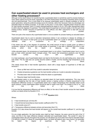
Typically, for a horizontal steam coil surrounded with water, 'U' values might be as low as 50 to 100 W/m )°C for
2
superheated steam but 1 200 W/m )°C for saturated steam, as depicted in Figure 2.3.4.
2
For steam to oil applications, the 'U' values might be considerably less, perhaps as low as 20 W/m )°C for
2
superheated steam and 150 W/m )°C for saturated steam.
2 2
In a shell and tube heat exchanger, 100 W/m )°C for superheated steam and 500 W/m )°C for saturated steam
can be expected. These figures are typical; actual figures will vary due to other design and operational
considerations.
Figure 2.3.4
Typical ‘U’ values for superheated
and saturated steam coils in water
Although the temperature of superheated steam is always higher than saturated steam at the same pressure, its
ability to transfer heat is therefore much lower. The overall effect is that superheated steam is much less effective
at transferring heat than saturated steam at the same pressure. The next Section 'Fouling' gives more detail.
Not only is superheated steam less effective at transferring heat, it is very difficult to quantify using Equation
2.5.3, = U A ΔT, as the temperature of the steam will fall as it gives up its heat while passing along the heating
surface.
Predicting the size of heat transfer surfaces utilising superheated steam is difficult and complex. In practice, the
basic data needed to perform such calculations is either not known or empirically obtained, putting their reliability
and accuracy in doubt.
Clearly, as superheated steam is less effective at transferring heat than saturated steam, then any heating area
using superheated steam would have to be larger than a saturated steam coil operating at the same pressure to
deliver the same heat flowrate.
If there is no choice but to use superheated steam, it is not possible to maintain steam in its superheated state
throughout the heating coil or heat exchanger, since as it gives up some of its heat content to the secondary fluid,
it cools towards saturation temperature. The amount of heat above saturation is quite small compared with the
large amount available as condensation occurs.
The steam should reach saturation relatively soon in the process; this allows the steam to condense to produce
higher heat transfer rates and result in a higher overall 'U' value for the whole coil, see Figure 2.3.5.
To help to enable this, superheated steam used for heat transfer purposes should not hold more than about 10°C
of superheat.
Figure 2.3.5
Less superheat allows the steam to condense
in the major part of the coil thus increasing
the overall ‘U’ value approaching that of saturated steam.
2
3. If this is so, it is relatively easy and practical to design a heat exchanger or a coil with a heating surface area
based upon saturated steam at the same pressure, by adding on a certain amount of surface area to allow for the
superheat. Using this guideline, the first part of a coil will be used purely to reduce the temperature of
superheated steam to its saturation point. The rest of the coil will then be able to take advantage of the higher
heat transfer ability of the saturated steam. The effect is that the overall 'U' value may not be much less than if
saturated steam were supplied to the coil.
From practical experience, if the extra heating area needed for superheated steam is 1% per 2°C of superheat,
the coil (or heat exchanger) will be large enough. This seems to work up to 10°C of superheat. It is not
recommended that superheated steam above 10°C of superheat be used for heating purposes due to the
probable disproportionate and uneconomic size of the heating surface, the propensity for fouling by dirt, and the
possibility of product spoilage by the high and uneven superheat temperatures.
Fouling
Fouling is caused by deposits building up on the heat transfer surface adding a resistance to heat flow. Many
process liquids can deposit sludge or scale on heating surfaces, and will do so at a faster rate at higher
temperatures. Further, superheated steam is a dry gas. Heat flowing from the steam to the metal wall must pass
through the static films adhering to the wall, which resist heat flow.
By contrast, the condensation of saturated steam causes the movement of steam towards the wall, and the
release of large quantities of latent heat right at the condensing surface. The combination of these factors means
that the overall heat transfer rates are much lower where superheated steam is present, even though the
temperature difference between the steam and the secondary fluid is higher.
Example 2.3.3 Sizing a tube bundle for superheated steam
Superheated steam at 3 bar g with 10°C of superheat (154°C) is to be used as the primary heat source for a shell
and tube process heat exchanger with a heating load of 250 kW, heating an oil based fluid from 80°C to 120°C
(making the arithmetic mean secondary temperature (ΔT AM) 100°C). Estimate the area of primary steam coil
required.
(Arithmetic mean temperature differences are used to keep this calculation simple; in practice, logarithmic mean
temperatures would be used for greater accuracy. Please refer to Tutorial 2.5 'Heat Transfer' for details on
arithmetic and logarithmic mean temperature differences).
First, consider the coil if it were heated by saturated steam at 3 bar g (144°C).
2
The 'U' value for saturated steam heating oil via a new carbon steel coil is taken to be 500 W/m °C.
3
4. Other applications using superheated steam
All the above applies when steam is flowing through a relatively narrow passage, such as the tubes in a shell and
tube heat exchanger or the plates in a plate heat exchanger.
In some applications, perhaps a drying cylinder in a paper machine, superheated steam is admitted to a greater
volume, when its velocity plummets to very small values. Here, the steam near the wall of the cylinder quickly
drops in temperature to near saturation and condensation begins. The heat flow through the wall is then the
same as if the cylinder were supplied with saturated steam. Superheat is present only within the 'core' in the
steam space and has no discernible effect on heat transfer rates.
There are instances where the presence of superheat can actually reduce the performance of a process, where
steam is being used as a process material.
One such process might involve moisture being imparted to the product from the steam as it condenses, such as,
the conditioning of animal feedstuff (meal) prior to pelletising. Here the moisture provided by the steam is an
essential part of the process; superheated steam would over-dry the meal and make pelletising difficult.
The effects of reducing steam pressure
In addition to the use of an additional heat exchanger (generally called a 'superheater'), superheat can also be
imparted to steam by allowing it to expand to a lower pressure as it passes through the orifice of a pressure
reducing valve. This is termed a throttling process with the lower pressure steam having the same enthalpy (apart
from a small amount lost to friction in passing through the valve) as the upstream high pressure steam. However,
the temperature of the throttled steam will always be lower than that of the supply steam.
The state of the throttled steam will depend upon:
The pressure of the supply steam.
The state of the supply steam.
The pressure drop across the valve orifice.
For supply steam below 30 bar g in the dry saturated state, any drop in pressure will produce superheated steam
after throttling. The degree of superheat will depend on the amount of pressure reduction.
For supply steam above 30 bar g in the dry saturated state, the throttled steam might be superheated, dry
saturated, or even wet, depending on the amount of pressure drop. For example, dry saturated steam at 60 bar g
would have to be reduced to approximately 10.5 bar g to produce dry saturated steam. Any less of a pressure
drop will produce wet steam, while any greater pressure drop would produce superheated steam.
Equally, the state of the supply steam at any pressure will influence the state of the throttled steam. For example,
wet steam at a pressure of 10 bar g and 0.95 dryness fraction would need to be reduced to 0.135 bar g to
produce dry saturated steam. Any less of a pressure drop would produce wet steam while any greater pressure
drop would superheat the throttled steam.
The Mollier chart is a plot of the specific enthalpy of steam against its specific entropy (sg).
Fig. 2.3.7
Enthalpy - entropy or Mollier chart for steam
4
5. Figure 2.3.7 shows a simplified, small scale version of the Mollier chart. The Mollier chart displays many different
relationships between enthalpy, entropy, temperature, pressure and dryness fraction. It may appear to be quite
complicated, due to the number of lines:
Constant enthalpy lines (horizontal).
Constant entropy lines (vertical).
The steam saturation curve across the centre of the chart divides it into a superheated steam region,
and a wet steam region. At any point above the saturation curve the steam is superheated, and at any
point below the saturation curve the steam is wet. The saturation curve itself represents the condition of
dry saturated steam at various pressures.
Constant pressure lines in both regions.
Constant temperature lines in the superheat region.
Constant dryness fraction (Χ) lines in the wet region.
A perfect expansion, for example within a steam turbine or a steam engine, is a constant entropy process, and
can be represented on the chart by moving vertically downwards from a point representing the initial condition to
a point representing the final condition.
Filmwise condensation
The elimination of the condensate film, is not quite as simple. As the steam condenses to give up its enthalpy of
evaporation, droplets of water may form on the heat transfer surface. These may then merge together to form a
continuous film of condensate. The condensate film may be between 100 and 150 times more resistant to heat
transfer than a steel heating surface, and 500 to 600 times more resistant than copper.
Dropwise condensation
If the droplets of water on the heat transfer surface do not merge immediately and no continuous condensate film
is formed, 'dropwise' condensation occurs. The heat transfer rates which can be achieved during
dropwisecondensation, are generally much higher than those achieved during filmwise condensation.
As a larger proportion of the heat transfer surface is exposed during dropwise condensation, heat transfer
coefficients may be up to ten times greater than those for filmwise condensation.
In the design of heat exchangers where dropwise condensation is promoted, the thermal resistance it produces is
often negligible in comparison to other heat transfer barriers. However, maintaining the appropriate conditions for
dropwise condensation have proved to be very difficult to achieve.
If the surface is coated with a substance that inhibits wetting, it may be possible to maintain dropwise
condensation for a period of time. For this purpose, a range of surface coatings such as Silicones, PTFE and an
assortment of waxes and fatty acids are sometimes applied to surfaces in a heat exchanger on which
condensation is to be promoted. However, these coatings will gradually lose their effectiveness due to processes
such as oxidation or fouling, and film condensation will eventually predominate.
As air is such a good insulator, it provides even more resistance to heat transfer. Air may be between 1 500 and
3 000 times more resistant to heat flow than steel, and 8 000 to 16 000 more resistant than copper. This means
that a film of air only 0.025 mm thick may resist as much heat transfer as a wall of copper 400 mm thick! Of
course all of these comparative relationships depend on the temperature profiles across each layer.
Figure 2.5.4 illustrates the effect this combination of layers has on the heat transfer process. These barriers to
heat transfer not only increase the thickness of the entire conductive layer, but also greatly reduce the mean
thermal conductivity of the layer.
The more resistant the layer to heat flow, the larger the temperature gradient is likely to be. This means that to
achieve the same desired product temperature, the steam pressure may need to be significantly higher.
The presence of air and water films on the heat transfer surfaces of either process or space heating applications
is not unusual. It occurs in all steam heated process units to some degree.
To achieve the desired product output and minimise the cost of process steam operations, a high heating
performance may be maintained by reducing the thickness of the films on the condensing surface. In practice, air
will usually have the most significant effect on heat transfer efficiency, and its removal from the supply steam will
increase heating performance.
5
6. Why return condensate and reuse it?
Financial reasons
Condensate is a valuable resource and even the recovery of small quantities is often economically justifiable. The
discharge from a single steam trap is often worth recovering.
Un-recovered condensate must be replaced in the boiler house by cold make-up water with additional costs of
water treatment and fuel to heat the water from a lower temperature.
Water charges
Any condensate not returned needs to be replaced by make-up water, incurring further water charges from the
local water supplier.
Effluent restrictions
In the UK for example, water above 43°C cannot be returned to the public sewer by law, because it is detrimental
to the environment and may damage earthenware pipes. Condensate above this temperature must be cooled
before it is discharged, which may incur extra energy costs. Similar restrictions apply in most countries, and
effluent charges and fines may be imposed by water suppliers for non-compliance.
Maximising boiler output
Colder boiler feedwater will reduce the steaming rate of the boiler. The lower the feedwater temperature, the
more heat, and thus fuel needed to heat the water, thereby leaving less heat to raise steam.
Boiler feedwater quality
Condensate is distilled water, which contains almost no total dissolved solids (TDS). Boilers need to be blown
down to reduce their concentration of dissolved solids in the boiler water. Returning more condensate to the
feedtank reduces the need for blowdown and thus reduces the energy lost from the boiler.
Summary of reasons for condensate recovery:
Water charges are reduced.
Effluent charges and possible cooling costs are reduced.
Fuel costs are reduced.
More steam can be produced from the boiler.
Boiler blowdown is reduced - less energy is lost from the boiler.
Chemical treatment of raw make-up water is reduced.
Figure 14.1.5 compares the amount of energy in a kilogram of steam and condensate at the same pressure. The
percentage of energy in condensate to that in steam can vary from 18% at 1 bar g to 30% at 14 bar g; clearly the
liquid condensate is worth reclaiming.
Fig. 14.1.5 Heat
content of steam and condensate at the same pressures
6