SlideShare una empresa de Scribd logo
1 de 6
Descargar para leer sin conexión
The term sinkhole receives a lot of use, and equal amounts
of abuse, in the popular media. Generally, anytime a hole or
depressionformsinthelandsurface,sometimesinashortperiod
oftime,itiscalledasinkhole.Sinkholesaregeologicfeaturesformed
by movement of rock or sediment into voids created by the
dissolution of water-soluble rock. Some sinkholes, such as the
infamous Winter Park, Florida, sinkhole of 1981 (Figure 1),
capture the attention of society as we view expensive homes
and automobiles teetering
on a precipice about to dis-
appear into the underworld.
Subsidence features caused
by other processes, such as
mine collapse and washouts
resulting from broken water
and sewer mains, are not true
sinkholes, but may be equally
as damaging. These features
also result from rock or soil
moving into a void, but the
void was a result of human
activities.
This paper compares the
effectiveness of various geo-
physical techniques in lo-
cating these two types of
subsidence features. For the
purposes of this paper, both
true sinkholes and anthro-
pogenic subsidence features
will be referred to as sink-
holes in keeping with the ver-
nacular usage.
Anthropogenic subsidence
features. Some of the more
costly sinkholes, in terms of
resourceandfinancialloss,go
largely unnoticed. For exam-
ple, the Retsof salt mine near
Cuylerville, NewYork (USA)
collapsed in March 1994 due
to weakened pillar design at
a depth of over 335 m in two
minor portions of the mine.
Two sections of the mine col-
lapsed providing a pathway
for the massive aquifer of the
overlyingGenesseeRiverval-
ley sediments to access the
open mined section and the
remaining unmined sections.
The subsequent flooding into
the mine approached 76 m3
per minute. This event low-
eredgroundwaterlevelsfrom
15 to 30 m in local wells and
over 125 m in the area of the
collapse. The collapse and
flooding resulted in abandonment of this, the second largest
saltmineintheworld,plusdestructionoffarmland,highways,
and bridges as the collapse worked its way to the surface
(Figure 2). This event had an impact on the national supply
of road salt and created substantial losses of jobs, but it is not
well known outside of the local community or the mining
industry. Geophysical surveys, including self potential and
seismic reflection, were employed in the early stages after the
initial collapse to define the
area of significant downward
waterflow,collapsedfeatures
at depth, and affected regions
in the overburden.
Similar sinkholes involv-
ing salt have happened in
Louisiana, when an oil explo-
ration well drilled into an
open subsurface salt mine
(Jefferson Island salt dome)
and emptied a surface lake
into the mine, and in sections
of Kansas where leaky brine
disposalwellshavedissolved
salt beds and generated sur-
face collapse.
Loss of property and in-
frastructureisnotuncommon
in towns such as Rock
Springs, Wyoming (USA)
where collapse of coal-mine
workingshasresultedinsink-
holes. In such areas, geo-
physical surveys, mainly
seismic reflection, have been
employed to map existing
underground workings,
thereby aiding hazard delin-
eation studies.
Compare these to hun-
dreds of times each year
when the nightly commute
home is blocked off because
a backhoe operator broke a
water main, and the roadway
is diverted around the “sink-
hole.”
Sinkholes and Florida. For
the remainder of this paper,
we will focus on examples
demonstrating the state of
geophysical practice in foren-
sic evaluation of sinkhole
potential within a well-
knownkarst(limestone)envi-
ronment of the United
States—namely Florida. In
Florida, concerns for public
safety and minimizing the
Geophysical applications to detect sinkholes
and ground subsidence
THOMAS L. DOBECKI, Shaw Environmental & Infrastructure, Tampa, Florida, USA
SAM B. UPCHURCH, SDII Global, Tampa, Florida, USA
336 THE LEADING EDGE MARCH 2006
Figure 1. Aerial photograph of the 1981 (limestone) sinkhole in Winter
Park, Florida. This collapse feature was approximately 100 m in diameter,
30 m deep, and formed in a matter of hours.
Figure 2. Photograph of edge of surface collapse/sinkhole feature formed
near Cuylerville, New York over a collapsed salt mine section approxi-
mately 335 m below land surface.
potential threat of sinkhole damage to commercial and resi-
dential properties has fueled the search for noninvasive tools
that could be used to warn the public of an imminent sub-
terranean threat.
Florida is famous for its limestone bedrock platform and
manyimpressivesinkholes.Manyofthelarge,roundsparkling
lakes found scattered throughout Florida owe their origins to
carbonatedissolutionactivity.Thecombinationofgeologically
young and shallow limestone, mobile sandy soil overburden,
and abundant groundwater yields an almost perfect recipe
for limestone dissolution, subsidence, and sinkhole formation.
Referring again to Figure 1, it is obvious that sinkholes can
form rapidly and without concern for current land use.
Because residential construction rarely includes thor-
ough subsurface testing, many homes and small commer-
cial structures are constructed over ancient sinkholes
(paleosinkholes) that have been buried and obscured by
subsequent depositional cycles of marine terrace deposits.
In addition, the limestone is soluble and often acidic shal-
low groundwater continues the process of dissolution and
formation of new voids in the limestone. Because of these
processes, the Florida
legislature has included
a statutory requirement
that homeowner’s in-
suranceincludeaprovi-
sion that covers
sinkhole-related dam-
age. The statute cur-
rently defines sinkhole
activity as the move-
ment of soil into voids
causedbydissolutionin
the underlying lime-
stone. It goes on to de-
fine sinkhole loss as
damage to the insured
structure as a result of
sinkhole activity. There-
fore, losses due to sub-
sidence associated with
mines, washouts, and
other human causes are
generally not covered.
There are many
other ways in which a
depression can form or
a house may experience
damage from move-
ment of earth materials.
For example, holes,
depressions, and/or
damage can be related
to heaving by tree roots,
decaying or compress-
ing organic matter (peat
soils, buried wood, de-
caying tree roots and
stumps), raveling of
soils into broken sewer
lines or septic tanks,
leaking or poorly con-
structed water wells
and swimming pools,
buried construction de-
bris, shrinking/ swel-
ling clay soils, leaking
MARCH 2006 THE LEADING EDGE 337
Figure 3. Photograph of a residential-scale sinkhole. The portable drilling
rig seen within the depression was in the process of drilling/testing soils
within a GPR anomaly area near a home when the drilling activity
caused sudden ground subsidence.
Figure 4. Example illustrat-
ing the sequence of develop-
ment of a cover-collapse
sinkhole in Florida.
water lines or irrigation pipes, very loose natural soils, and
animal burrowing.
Estimates of monetary damages caused by sinkhole
activity are difficult to quantify because much information
concerning property damage and payouts is proprietary. A
2002 investigation by Florida State University reported on
an analysis of 877 Florida sinkhole claims filed between
1996 and 2001. Average payout per claim was US$62 628. In
2004, one of the largest of the insurers in Florida reported pay-
ing out about $6 million in sinkhole claims, and it estimated
that overall owner compensation for sinkhole claims could be
as high as $25 million in 2004.
In 2005, the Florida Legislature rewrote the law requiring
sinkhole insurance. Previously, geophysical investigations
were not required, but they had become “industry accepted”
investigation techniques. In 2005, the statutes specified cer-
tain investigation protocols, including geophysical investiga-
tions, to identify anomalous conditions that might reflect
sinkhole activity. Occasionally, the type, location, and degree
of damage makes defensible identification of sinkhole activ-
ity simple (Figure 3), but these cases are the exception and not
the rule. Ground truth confirmation of the components of a
sinkhole (as defined) is required, but blind drilling across a
property is fruitless because of the low probability of drilling
into such a potential sinkhole feature as well as the possibil-
ity of breaching confining layers and exacerbating sinkhole
development. Drill testing should be minimized and per-
formed within anomalies interpreted from geophysical find-
ings. In Figure 3, we see a portable drilling rig that has fallen
into a ground depression adjacent to a home. The depression
formed during the drilling of an anomalous feature detected
during a geophysical survey. Geophysical surveys provide an
important link in the chain of tests that will determine sink-
hole activity or relate damage to some other cause.
First, geologic evidence must support the assumption that
we are in a geologic locale that is conducive to sinkhole gen-
eration (e.g., shallow carbonates overlain by mobile sedi-
ments).Giventhat,therearethreecharacteristicsunderFlorida
statutes that must be present before a site can be associated
with sinkhole activity (Figure 4):
• There must be a void volume in the limestone that is capa-
ble of accepting sediments.
• There must be evidence of material raveling downward
into such a void.
• There must be damage consistent with sinkhole activity,
or a surface depression, and/or evidence that a depres-
sion is forming.
The first and third criteria are of secondary importance as
compared to evidence of raveling. First, it is almost impossi-
ble to drill a borehole in Florida and not eventually encounter
338 THE LEADING EDGE MARCH 2006
Figure 5. Two-dimensional GPR transect showing significant depression and discontinuity of a deep clay horizon and, to a much lesser extent, distur-
bance of overlying clastic sediments. Limestone bedrock (not observed) underlies this section approximately 30 m below land surface.
a void — voids are ubiquitous so they
do not define a sinkhole.
Certaintypesofdamagetoastruc-
ture can be construed as an indication
of ground movement. Therefore, a
filed damage claim identifying spe-
cific types of structural damage rep-
resents a testable argument that the
surface is moving or has moved.
Subsurface evidence of raveling,
therefore, is generally the most impor-
tant criterion to be resolved. The final
word on raveling is determined by
geotechnicaltesting(i.e.,standardpen-
etration tests or cone penetrometer
soundings), but the key role in apply-
ing geophysics is, as usual, determin-
ing the proper or optimal locations for
such tests.
The role of geophysical investiga-
tions. “Raveling” is the process by
which water transports soil down-
ward into voids/cavities in underly-
ing strata. The ravel zone is, therefore,
a volume of soil that is looser (higher
porosity) and has less subsequent strength than nonraveled
soils. So the targets for subsurface testing are areas where
soil layers are depressed, discontinuous, or truncated and
where there is a volume of loose or low-strength soil. So,
methods that are sensitive to changes in density, porosity,
and strength are ideal for identification of areas for sub-
surface testing.
The most commonly used and recommended geophysi-
cal surveys for the investigation of potential sinkhole activity
include ground-penetrating radar (GPR), two-dimensional
electrical resistivity tomography (ERT), and seismic methods
(refraction tomography, reflection, surface wave inversion).
Microgravity surveying has been used for sinkhole detection
but, because of the ease and success of the other mentioned
techniques, little has been done in Florida. The following will
describe the application and advantages/disadvantages of
each method using real data examples.
GPR. GPR is the overwhelming geophysical method of
choice for sinkhole investigations. This stems from Florida’s
famous dry, high-resistivity surficial sands, which translate
into relatively deep GPR penetration (typically 5-10 m). GPR
provides the opportunity for dense data coverage (includ-
ing 3D coverage), high resolution, and very good penetra-
tion with quick turnaround and relatively low cost.Another
plus is that GPR profiles can be acquired within some struc-
tures by shooting through the floor slab. Reinforcing steel
(rebar) limits the range of antenna frequencies (typically >400
MHz) that may be used to shoot through the slab. Difficulties
arise when a site has shallow clay or shallow, salty ground-
water. However, when the target of the investigation is to
establish evidence of subsidence, the presence of clay is less
of an issue than might be expected. If all we can image is
the top of the clay and it can be shown that the clay is mov-
ing or is locally disrupted due to raveling, the GPR section
still provides useful information.
A ravel zone can also be viewed directly on GPR sec-
tions as a near-vertical zone of discrete scatterers and local
increases in reflection amplitudes in the shallow section
because of localized increases in soil porosity. Also, if fines
(clay) are removed by the raveling process, such features
are sometimes identified by a localized interval of increased
GPR signal penetration due to the reduced electrical con-
ductivity/attenuation.
The GPR section of Figure 5 exhibits a depression in a
strong reflection. This GPR reflection correlates with a thin
clay layer identified in local drill holes. The clay horizon
shows a substantial depression, but we also note that over-
lying soil horizons exhibit only minor disturbance. Multiple,
orthogonal GPR transects over the same general area of the
single section enabled mapping of the top of this clay hori-
zon (Figure 6). The surface map of this single layer exhibits
a significant depression that has a quasi-circular footprint,
which are key indicators that this anomalous area is a poten-
tial buried sinkhole structure even though the ground sur-
face is quite level. The apparent, undisturbed nature of the
shallower soil horizons suggest that this may be an inactive
(paleo) sinkhole, but follow up geotechnical drilling would
be required within the feature to determine its potential
activity. However, geophysical survey results ensure that
such invasive testing is performed in optimum locations.
ERT. 2D electrical resistivity tomography profiling (sur-
face electrode arrays) is also used commonly for sinkhole
investigations as a means of identifying the ravel zone and,
under ideal circumstances (shallow limestone and large dis-
solution features), the underlying void or cavity. The ravel
zone is characterized by increased porosity and reduced per-
centage of fines. Depending on depth to the local ground-
water table, the ravel zone can either be a high-resistivity
anomaly (if dry) or a low-resistivity anomaly (if saturated).
Deeper void space is typically characterized by a low-resis-
tivity feature indicative of carbonate materials being replaced
by looser clastic sediments or by water. Of course, an air-
filled void would generate a high-resistivity anomaly fea-
ture, but this would not constitute a sinkhole (by legal
definition) because it has not collapsed or accepted overly-
ing sediments.
ERT, in the context of sinkhole exploration within resi-
dential or commercially developed properties, is generally
more affected and, therefore, influenced by cultural noise
sources (utilities, piping) and the limited areal space avail-
able for surveying (considering the maximum dimension of
a typical residential lot may be 20 ǂ 30 m or less and the
MARCH 2006 THE LEADING EDGE 339
Figure 6. Surface representation of the top of the same
deep clay horizon in Figure 5 as constructed from an
orthogonal grid of GPR transects. The depression seen
in the section view exhibits a nearly circular pattern in
plan view, also suggesting sinkhole conditions.
adjacent house may be only 3 m away). Also, space limita-
tions mandate ERT lines be acquired so close to houses or
structures that offline (3D) effects of foundations and swim-
ming pool structures influence the readings and can pro-
duce false anomalies. In spite of these limitations, at least
one major insurer in Florida suggests a combination of GPR
and ERT be used for all its sinkhole claim investigations.
ERT sections acquired in a karst area but not in an urban-
ized environment clearly display the
typesofanomaliesroutinelyencoun-
tered and confirmed as sinkholes
(Figure 7). In the area where these
sample data sets were acquired,
dolomitic carbonates are known to
exist in the upper 10 m, and expo-
sures (quarries) in the area show
significant karst development (dis-
solution features, pinnacles). The
ERTsectionsshowamantleoflower-
resistivity silts and clayey sands
overlying higher-resistivity dolo-
mite.Anomalous areas are observed
where we see penetration of lower-
resistivitymaterialsintothedolomite
indicating potential dissolution fea-
tures that have been filled with surfi-
cial sediments or areas with
extensiveweatheringofthedolomite
(e.g., along fractured volumes).
ERT sections acquired in an
urban setting (within 4 m of a house
foundation) clearly possess lower
signal-to-noise in comparison with
sections acquired in undeveloped
areas (Figure 8). We note the very
high-resistivity surficial sands (a
common Florida feature) and an
anomalous area near the 11-m mark
on the left side of the section where
we see a thickening/deepening of
the high-resistivity layer, possibly
indicative of raveling. However, the
section between 9.1 and 27.4 m is
consistent with where the ERT tran-
sect abuts against the footprint of the
house (also indicated on Figure 8),
and anomalous areas coincide with
that interval. This, too, is a common
observation when conducting ERT
adjacent to a house foundation.
Anomaliesgenerallyoccuratthecor-
ner of a foundation. This suggests
that the house itself, in the example
of Figure 8, could be influencing the
inversion results (3D effects on a 2D
inversion process). However, com-
plementaryGPRprofilesinthesame
area plus a visible depression that
was forming beneath the slab of the
house (both shown on Figure 8) sug-
gest that this ERT anomaly is actu-
ally a raveling anomaly. Subsequent
drilling confirmed this interpreta-
tion.Thisexamplealsoindicateswhy
multiple data sets and complemen-
tary views of the subsurface are nec-
essary for proper interpretation in
a developed urban setting.
Seismic methods. The key feature of a ravel zone that
makes it an attractive target for seismic surveying is the loos-
ened, weak nature of the sediments relative to adjacent,
undisturbed soils. This makes a ravel zone an anomalous
area where reduced seismic velocities are commonly
expected and observed. In areas of shallow water table
depths, this would mean that shear-wave-based seismic
340 THE LEADING EDGE MARCH 2006
Figure 7. Two examples of electrical resistivity tomography (ERT) images acquired in a rural setting
within a karst geologic environment. The dolomitic bedrock is identified with the higher (>1000 ohm-m)
green-to-red resistivities and the clayey soil mantle by the bluer shades (<50 ohm-m). Note in both
examples the apparent breaches in the bedrock indicated by finger-like projections of lower-resistivity
materials into the bedrock.
Figure 8. Example data sets (ERT and GPR) acquired in close proximity to a house. The ERT shows a
possible ravel zone anomaly (circled) near the 11-m mark; however, that location also corresponds to the
corner of the house foundation (indicated above the ERT section). The GPR section shows a broad
depression plus a discontinuity in a deep reflector that correlates with the position of the ERT anomaly.
A void area beneath the house slab (photograph) found in the same general location confirms the inter-
pretation of sinkhole conditions.
methods would be particularly sensitive to the detection and
mapping of such loose soil volumes. Further, because of the
typically large velocity contrast between the soils and car-
bonate bedrock, seismic methods are also very good at map-
ping depressions on the bedrock surface.
The most common seismic method utilized for sinkhole
definition has been seismic refraction tomography (SRT)
using S-waves, when possible. Tomographic processing of
the refraction data set is required because the ravel zone will
represent a local, lateral variation/anomaly in the shear-
wave velocity field (and, to a lesser extent, the P-wave veloc-
ity field if fully saturated) that is poorly handled by more
classical ray-trace interpretation methods. Figure 9 is a P-
wave refraction tomography section acquired not in Florida
but in Texas where a road failure occurred associated with
drilling near a salt dome structure. The section clearly shows
development of a pair of lobe volumes of reduced strength/
lower-velocity materials that are extending downward into
more competent, higher-velocity (redder) materials. The
position and magnitude of the surface collapse is indicated
by the depression in the surface topography.
A unique characteristic of refraction tomography that is
enticing as a future development is broadside shooting, or
undershooting, where geophone spreads are extended along
one side of a house and the seismic sources are deployed
along the other sides. This would enable generation of a
velocity map under the house. Invasive testing through floor
slabs can be done (minidrills or cone penetrometer systems),
but methods are limited as to where they can be applied, and
they are very damaging to the floor, as one would imagine.
So this potential noninvasive means to look under houses
would be an attractive development. Undershooting would
also offer an advantage over borehole-to-borehole seismic
tomography because it would sample in a horizontal plane
and thereby maximize the chance of shooting through a ver-
tical, low-velocity column. Such a vertical column could fall
outside of the vertical plane defined by the two boreholes.
Also, boreholes are always expensive (relative to the cost of
geophysical surveys of this type) and represent a potential
pathway or breach in a confining layer that should be avoided
when possible.
Another seismic technique that has had limited applica-
tion but offers great promise for defining ravel zones is the
MASW (multichannel analysis of surface waves) technique.
This technique also maps S-wave velocity variation but has
the additional capability of detecting and mapping velocity
inversions (decreases with depth) and, so, may have a unique
ability to detect incipient ravel zones (i.e., sinkholes in the
formative process that have yet to reach land surface).
Reflection surveys have typically been applied, on a spo-
radic basis, to the deep sensing of depressions on the top of
rock surface or detecting cavities within the rock mass itself.
With the development of tomographic imaging techniques
that will better define structure in the overlying sediments,
there may be increased application of reflection methods for
sinkhole delineation.
Summary. Sinkholes, then, regardless of their underlying
cause, represent hazards that can be extremely costly and dis-
ruptive to society in general, are ubiquitous in where they
occur, and happen routinely. Geophysics provides important
tools that can be used to:
• Predict where and within what limits sinkholes are likely
to occur (planning; risk assessment).
• Determine the underlying cause of an existing or form-
ing subsidence or depression (forensic evaluation).
• Evaluate the success or failure of ground improvement
programs (grouting, compaction, mechanical stabiliza-
tion) intended to “fix” sinkhole conditions (remediation).
The sinkhole remediation aspect is taking on renewed
emphasis as communities and agencies realize that the sink-
hole often offers a rapid, high-permeability pathway to intro-
duce surface contaminants into the groundwater system. So
while the surface depression offers a tempting area to dis-
pose of old vehicles and trash, there are severe consequences
lurking within such activities.
Suggested reading. “Sinkholes, west-central Florida” by
Tihansky (in Land Subsidence in the United States, USGS Circular
1182, 1999). “The Retsof Salt Mine Collapse” by Kappel et al.
(in Land Subsidence in the United States). Mitigating Losses from
Land Subsidence in the United States (Commission on Engineering
and Technical Systems, National Academy Press, 1991). TLE
Corresponding author: tom.dobecki@shawgrp.com
MARCH 2006 THE LEADING EDGE 341
Figure 9. P-wave refraction tomography section acquired adjacent to a ground depression/sinkhole that formed adjacent to a salt dome structure in
Texas. Interpreted ravel zones are indicated by the two lobate features of decreased seismic velocity.
Copyright © 2006, The Society of Exploration Geophysicists

Más contenido relacionado

La actualidad más candente

4 foundation geology
4 foundation geology4 foundation geology
4 foundation geologyRaghav Gadgil
 
Joints and unconfirmity
Joints and unconfirmityJoints and unconfirmity
Joints and unconfirmityshruthiv19
 
Natural hazards and disaster,types,mitigation and management
Natural hazards and disaster,types,mitigation and managementNatural hazards and disaster,types,mitigation and management
Natural hazards and disaster,types,mitigation and managementkamal brar
 
Liquefaction and liquefaction potential
Liquefaction and liquefaction potentialLiquefaction and liquefaction potential
Liquefaction and liquefaction potentialMahesh Raj Bhatt
 
disaster managment - AKSHAY WILSON
disaster managment - AKSHAY WILSONdisaster managment - AKSHAY WILSON
disaster managment - AKSHAY WILSONAkshay Wilson
 
Lateral earth pressure
Lateral earth pressureLateral earth pressure
Lateral earth pressureAndre Az
 
ASSESSMENT OF LIQUEFACTION POTENTIAL OF SOIL USING MULTI-LINEAR REGRESSION MO...
ASSESSMENT OF LIQUEFACTION POTENTIAL OF SOIL USING MULTI-LINEAR REGRESSION MO...ASSESSMENT OF LIQUEFACTION POTENTIAL OF SOIL USING MULTI-LINEAR REGRESSION MO...
ASSESSMENT OF LIQUEFACTION POTENTIAL OF SOIL USING MULTI-LINEAR REGRESSION MO...IAEME Publication
 
Earthquake causes and safety measurements
Earthquake causes and safety measurementsEarthquake causes and safety measurements
Earthquake causes and safety measurementsM Aamer Raza
 
Natural Hazards, Classification and Analysis
Natural Hazards, Classification and AnalysisNatural Hazards, Classification and Analysis
Natural Hazards, Classification and AnalysisPaul Wozney
 
GROUNDWATER LEVEL FLUCTUATION
GROUNDWATER LEVEL FLUCTUATIONGROUNDWATER LEVEL FLUCTUATION
GROUNDWATER LEVEL FLUCTUATIONharikrishnankch
 
Geography / natural Hazards
Geography / natural HazardsGeography / natural Hazards
Geography / natural HazardsR.P.Perera
 
Importance of geological considerations while choosing tunnel sites and align...
Importance of geological considerations while choosing tunnel sites and align...Importance of geological considerations while choosing tunnel sites and align...
Importance of geological considerations while choosing tunnel sites and align...Buddharatna godboley
 

La actualidad más candente (20)

4 foundation geology
4 foundation geology4 foundation geology
4 foundation geology
 
Joints and unconfirmity
Joints and unconfirmityJoints and unconfirmity
Joints and unconfirmity
 
Natural hazards and disaster,types,mitigation and management
Natural hazards and disaster,types,mitigation and managementNatural hazards and disaster,types,mitigation and management
Natural hazards and disaster,types,mitigation and management
 
Liquefaction and liquefaction potential
Liquefaction and liquefaction potentialLiquefaction and liquefaction potential
Liquefaction and liquefaction potential
 
Natural hazards
Natural hazardsNatural hazards
Natural hazards
 
Sinkholes
SinkholesSinkholes
Sinkholes
 
disaster managment - AKSHAY WILSON
disaster managment - AKSHAY WILSONdisaster managment - AKSHAY WILSON
disaster managment - AKSHAY WILSON
 
Lateral earth pressure
Lateral earth pressureLateral earth pressure
Lateral earth pressure
 
ASSESSMENT OF LIQUEFACTION POTENTIAL OF SOIL USING MULTI-LINEAR REGRESSION MO...
ASSESSMENT OF LIQUEFACTION POTENTIAL OF SOIL USING MULTI-LINEAR REGRESSION MO...ASSESSMENT OF LIQUEFACTION POTENTIAL OF SOIL USING MULTI-LINEAR REGRESSION MO...
ASSESSMENT OF LIQUEFACTION POTENTIAL OF SOIL USING MULTI-LINEAR REGRESSION MO...
 
Earthquake causes and safety measurements
Earthquake causes and safety measurementsEarthquake causes and safety measurements
Earthquake causes and safety measurements
 
Natural Hazards, Classification and Analysis
Natural Hazards, Classification and AnalysisNatural Hazards, Classification and Analysis
Natural Hazards, Classification and Analysis
 
Geohazards
GeohazardsGeohazards
Geohazards
 
Liquefaction
LiquefactionLiquefaction
Liquefaction
 
Natural hazards
Natural hazardsNatural hazards
Natural hazards
 
Geology of Dams
Geology of DamsGeology of Dams
Geology of Dams
 
Natural hazards and disaster management
Natural hazards and disaster managementNatural hazards and disaster management
Natural hazards and disaster management
 
GROUNDWATER LEVEL FLUCTUATION
GROUNDWATER LEVEL FLUCTUATIONGROUNDWATER LEVEL FLUCTUATION
GROUNDWATER LEVEL FLUCTUATION
 
Geography / natural Hazards
Geography / natural HazardsGeography / natural Hazards
Geography / natural Hazards
 
Importance of geological considerations while choosing tunnel sites and align...
Importance of geological considerations while choosing tunnel sites and align...Importance of geological considerations while choosing tunnel sites and align...
Importance of geological considerations while choosing tunnel sites and align...
 
Sinkholes
SinkholesSinkholes
Sinkholes
 

Destacado

Friends, Fans, and Followers: Uses of Social Media in Public Transportation
Friends, Fans, and Followers: Uses of Social Media in Public TransportationFriends, Fans, and Followers: Uses of Social Media in Public Transportation
Friends, Fans, and Followers: Uses of Social Media in Public TransportationSusan Bregman
 
Jayalakshmi Parasaram_ SAP Business Objects Consultant_8+years
Jayalakshmi Parasaram_ SAP Business Objects Consultant_8+yearsJayalakshmi Parasaram_ SAP Business Objects Consultant_8+years
Jayalakshmi Parasaram_ SAP Business Objects Consultant_8+yearsJayalakshmi parasaram
 
Lawshare, I-COM & ETSOS
Lawshare, I-COM & ETSOSLawshare, I-COM & ETSOS
Lawshare, I-COM & ETSOSRachel Bell
 
Daily livestock report jan 25 2013
Daily livestock report jan 25 2013Daily livestock report jan 25 2013
Daily livestock report jan 25 2013joseleorcasita
 
Chapter 2.1: The College Chapter of DOOM
Chapter 2.1: The College Chapter of DOOMChapter 2.1: The College Chapter of DOOM
Chapter 2.1: The College Chapter of DOOMFire Eternal
 
Simbologia del-diagrama-de-flujo
Simbologia del-diagrama-de-flujoSimbologia del-diagrama-de-flujo
Simbologia del-diagrama-de-flujoLuz Zaragoza Chavez
 
Benchmark Report - CRM Database Managers
Benchmark Report - CRM Database ManagersBenchmark Report - CRM Database Managers
Benchmark Report - CRM Database ManagersLauren Barber
 
Inventario Forestal: Bosques de Producción Permanente de la Región Ucayali
Inventario Forestal: Bosques de Producción Permanente de la Región UcayaliInventario Forestal: Bosques de Producción Permanente de la Región Ucayali
Inventario Forestal: Bosques de Producción Permanente de la Región UcayaliSerfor Perú
 
Unit vi(dsc++)
Unit vi(dsc++)Unit vi(dsc++)
Unit vi(dsc++)Durga Devi
 
Tecnologia de ruptura
Tecnologia de rupturaTecnologia de ruptura
Tecnologia de rupturaRRinvestiga
 
Πληροφορίες για το Υποβρύχιο
Πληροφορίες για το ΥποβρύχιοΠληροφορίες για το Υποβρύχιο
Πληροφορίες για το ΥποβρύχιοAngel
 
Vocabulary exercises + answers
Vocabulary exercises + answersVocabulary exercises + answers
Vocabulary exercises + answersDavid Deubelbeiss
 
Ft aparelho reprodutor
Ft aparelho reprodutorFt aparelho reprodutor
Ft aparelho reprodutorCláudia Moura
 

Destacado (18)

Friends, Fans, and Followers: Uses of Social Media in Public Transportation
Friends, Fans, and Followers: Uses of Social Media in Public TransportationFriends, Fans, and Followers: Uses of Social Media in Public Transportation
Friends, Fans, and Followers: Uses of Social Media in Public Transportation
 
Jayalakshmi Parasaram_ SAP Business Objects Consultant_8+years
Jayalakshmi Parasaram_ SAP Business Objects Consultant_8+yearsJayalakshmi Parasaram_ SAP Business Objects Consultant_8+years
Jayalakshmi Parasaram_ SAP Business Objects Consultant_8+years
 
Lawshare, I-COM & ETSOS
Lawshare, I-COM & ETSOSLawshare, I-COM & ETSOS
Lawshare, I-COM & ETSOS
 
Daily livestock report jan 25 2013
Daily livestock report jan 25 2013Daily livestock report jan 25 2013
Daily livestock report jan 25 2013
 
Chapter 2.1: The College Chapter of DOOM
Chapter 2.1: The College Chapter of DOOMChapter 2.1: The College Chapter of DOOM
Chapter 2.1: The College Chapter of DOOM
 
Which Half is Wasted?
Which Half is Wasted?Which Half is Wasted?
Which Half is Wasted?
 
Simbologia del-diagrama-de-flujo
Simbologia del-diagrama-de-flujoSimbologia del-diagrama-de-flujo
Simbologia del-diagrama-de-flujo
 
Benchmark Report - CRM Database Managers
Benchmark Report - CRM Database ManagersBenchmark Report - CRM Database Managers
Benchmark Report - CRM Database Managers
 
Inventario Forestal: Bosques de Producción Permanente de la Región Ucayali
Inventario Forestal: Bosques de Producción Permanente de la Región UcayaliInventario Forestal: Bosques de Producción Permanente de la Región Ucayali
Inventario Forestal: Bosques de Producción Permanente de la Región Ucayali
 
Unit vi(dsc++)
Unit vi(dsc++)Unit vi(dsc++)
Unit vi(dsc++)
 
Ashton
AshtonAshton
Ashton
 
Tecnologia de ruptura
Tecnologia de rupturaTecnologia de ruptura
Tecnologia de ruptura
 
Idioms for idiots
Idioms for idiotsIdioms for idiots
Idioms for idiots
 
infancia en mexico reporte
infancia en mexico reporteinfancia en mexico reporte
infancia en mexico reporte
 
Hackathon
HackathonHackathon
Hackathon
 
Πληροφορίες για το Υποβρύχιο
Πληροφορίες για το ΥποβρύχιοΠληροφορίες για το Υποβρύχιο
Πληροφορίες για το Υποβρύχιο
 
Vocabulary exercises + answers
Vocabulary exercises + answersVocabulary exercises + answers
Vocabulary exercises + answers
 
Ft aparelho reprodutor
Ft aparelho reprodutorFt aparelho reprodutor
Ft aparelho reprodutor
 

Similar a SINKHOLE GEOPHYSICS

pdf_20230508_010354_0000 (1).pdf
pdf_20230508_010354_0000 (1).pdfpdf_20230508_010354_0000 (1).pdf
pdf_20230508_010354_0000 (1).pdfMaggelAnclote2
 
Gulf of Mexico Hydrate Mounds
Gulf of Mexico Hydrate MoundsGulf of Mexico Hydrate Mounds
Gulf of Mexico Hydrate MoundsB.Nicole Barry
 
Chapter 6 (other related geological hazard)
Chapter 6 (other related geological hazard)Chapter 6 (other related geological hazard)
Chapter 6 (other related geological hazard)carminajoysibayan1
 
Midwest Archaeological Conference Poster
Midwest Archaeological Conference Poster Midwest Archaeological Conference Poster
Midwest Archaeological Conference Poster Jonathan King
 
Liquefaction by alisha kaplan
Liquefaction by alisha kaplanLiquefaction by alisha kaplan
Liquefaction by alisha kaplanmk.amiri
 
Liquefaction of Soil Geotech
Liquefaction of Soil GeotechLiquefaction of Soil Geotech
Liquefaction of Soil GeotechNouman Warraich
 
Unit 8 Moving ground
Unit 8 Moving groundUnit 8 Moving ground
Unit 8 Moving groundE2 Consulting
 
Causes of gEOLOGIC hAZARDS.docx
Causes of gEOLOGIC hAZARDS.docxCauses of gEOLOGIC hAZARDS.docx
Causes of gEOLOGIC hAZARDS.docxBalaoroDheoLubang
 
Land Subsidence Introduction Of all water that r.docx
Land Subsidence  Introduction  Of all water that r.docxLand Subsidence  Introduction  Of all water that r.docx
Land Subsidence Introduction Of all water that r.docxsmile790243
 
CEE553_Gummaraj_Bharath_Final_Proposal
CEE553_Gummaraj_Bharath_Final_ProposalCEE553_Gummaraj_Bharath_Final_Proposal
CEE553_Gummaraj_Bharath_Final_ProposalBharath Gummaraj
 
Undergraduate Scholars Forum 2016
Undergraduate Scholars Forum 2016Undergraduate Scholars Forum 2016
Undergraduate Scholars Forum 2016Jonathan King
 
Dark clouds over Clayton Valley and green lights for Belmont‘s Kibby Basin Pr...
Dark clouds over Clayton Valley and green lights for Belmont‘s Kibby Basin Pr...Dark clouds over Clayton Valley and green lights for Belmont‘s Kibby Basin Pr...
Dark clouds over Clayton Valley and green lights for Belmont‘s Kibby Basin Pr...Follow me on Twitter @Stockshaman
 
DRRR – Other Geological Hazards
DRRR – Other Geological HazardsDRRR – Other Geological Hazards
DRRR – Other Geological HazardsReid Manares
 
Green liquefaction arrangement
Green liquefaction arrangementGreen liquefaction arrangement
Green liquefaction arrangementDesireddy Manasa
 
16. the astonishing genesis flood, part 3
16. the astonishing genesis flood, part 316. the astonishing genesis flood, part 3
16. the astonishing genesis flood, part 3Ariel Roth
 
Orchard Beach, Pelham BayVirtual Field TripWhere are.docx
Orchard Beach, Pelham BayVirtual Field TripWhere are.docxOrchard Beach, Pelham BayVirtual Field TripWhere are.docx
Orchard Beach, Pelham BayVirtual Field TripWhere are.docxhopeaustin33688
 
Orchard Beach, Pelham BayVirtual Field TripWhere are
Orchard Beach, Pelham BayVirtual Field TripWhere areOrchard Beach, Pelham BayVirtual Field TripWhere are
Orchard Beach, Pelham BayVirtual Field TripWhere arelianaalbee2qly
 

Similar a SINKHOLE GEOPHYSICS (20)

pdf_20230508_010354_0000 (1).pdf
pdf_20230508_010354_0000 (1).pdfpdf_20230508_010354_0000 (1).pdf
pdf_20230508_010354_0000 (1).pdf
 
Gulf of Mexico Hydrate Mounds
Gulf of Mexico Hydrate MoundsGulf of Mexico Hydrate Mounds
Gulf of Mexico Hydrate Mounds
 
Sinkholes in karst environments
Sinkholes in karst environmentsSinkholes in karst environments
Sinkholes in karst environments
 
Chapter 6 (other related geological hazard)
Chapter 6 (other related geological hazard)Chapter 6 (other related geological hazard)
Chapter 6 (other related geological hazard)
 
Midwest Archaeological Conference Poster
Midwest Archaeological Conference Poster Midwest Archaeological Conference Poster
Midwest Archaeological Conference Poster
 
Liquefaction by alisha kaplan
Liquefaction by alisha kaplanLiquefaction by alisha kaplan
Liquefaction by alisha kaplan
 
Liquefaction of Soil Geotech
Liquefaction of Soil GeotechLiquefaction of Soil Geotech
Liquefaction of Soil Geotech
 
Unit 8 Moving ground
Unit 8 Moving groundUnit 8 Moving ground
Unit 8 Moving ground
 
Causes of gEOLOGIC hAZARDS.docx
Causes of gEOLOGIC hAZARDS.docxCauses of gEOLOGIC hAZARDS.docx
Causes of gEOLOGIC hAZARDS.docx
 
Land Subsidence Introduction Of all water that r.docx
Land Subsidence  Introduction  Of all water that r.docxLand Subsidence  Introduction  Of all water that r.docx
Land Subsidence Introduction Of all water that r.docx
 
CEE553_Gummaraj_Bharath_Final_Proposal
CEE553_Gummaraj_Bharath_Final_ProposalCEE553_Gummaraj_Bharath_Final_Proposal
CEE553_Gummaraj_Bharath_Final_Proposal
 
On Slope Monitoring Methods
On Slope Monitoring MethodsOn Slope Monitoring Methods
On Slope Monitoring Methods
 
Undergraduate Scholars Forum 2016
Undergraduate Scholars Forum 2016Undergraduate Scholars Forum 2016
Undergraduate Scholars Forum 2016
 
Geology Terms
Geology TermsGeology Terms
Geology Terms
 
Dark clouds over Clayton Valley and green lights for Belmont‘s Kibby Basin Pr...
Dark clouds over Clayton Valley and green lights for Belmont‘s Kibby Basin Pr...Dark clouds over Clayton Valley and green lights for Belmont‘s Kibby Basin Pr...
Dark clouds over Clayton Valley and green lights for Belmont‘s Kibby Basin Pr...
 
DRRR – Other Geological Hazards
DRRR – Other Geological HazardsDRRR – Other Geological Hazards
DRRR – Other Geological Hazards
 
Green liquefaction arrangement
Green liquefaction arrangementGreen liquefaction arrangement
Green liquefaction arrangement
 
16. the astonishing genesis flood, part 3
16. the astonishing genesis flood, part 316. the astonishing genesis flood, part 3
16. the astonishing genesis flood, part 3
 
Orchard Beach, Pelham BayVirtual Field TripWhere are.docx
Orchard Beach, Pelham BayVirtual Field TripWhere are.docxOrchard Beach, Pelham BayVirtual Field TripWhere are.docx
Orchard Beach, Pelham BayVirtual Field TripWhere are.docx
 
Orchard Beach, Pelham BayVirtual Field TripWhere are
Orchard Beach, Pelham BayVirtual Field TripWhere areOrchard Beach, Pelham BayVirtual Field TripWhere are
Orchard Beach, Pelham BayVirtual Field TripWhere are
 

Más de Ali Osman Öncel

Riskli Yapılar - Çevre ve Şehircilik
Riskli Yapılar - Çevre ve ŞehircilikRiskli Yapılar - Çevre ve Şehircilik
Riskli Yapılar - Çevre ve ŞehircilikAli Osman Öncel
 
Riskli Yapılar -Çevre ve Şehircilik
Riskli Yapılar -Çevre ve ŞehircilikRiskli Yapılar -Çevre ve Şehircilik
Riskli Yapılar -Çevre ve ŞehircilikAli Osman Öncel
 
Kar Kar Geothermal Field Work
Kar Kar Geothermal Field WorkKar Kar Geothermal Field Work
Kar Kar Geothermal Field WorkAli Osman Öncel
 
High Resolution Earth's Gravitational Field
High Resolution Earth's Gravitational FieldHigh Resolution Earth's Gravitational Field
High Resolution Earth's Gravitational FieldAli Osman Öncel
 
Gravity Predictions for Earthquakes
Gravity Predictions for EarthquakesGravity Predictions for Earthquakes
Gravity Predictions for EarthquakesAli Osman Öncel
 
Nakamura Technique for Soil Characterization
Nakamura Technique for Soil CharacterizationNakamura Technique for Soil Characterization
Nakamura Technique for Soil CharacterizationAli Osman Öncel
 
Geopsy: Seismic Vibration Processing
Geopsy: Seismic Vibration ProcessingGeopsy: Seismic Vibration Processing
Geopsy: Seismic Vibration ProcessingAli Osman Öncel
 

Más de Ali Osman Öncel (20)

APA Yazım Kuralları
APA Yazım KurallarıAPA Yazım Kuralları
APA Yazım Kuralları
 
Gravimetri : Ders 14
Gravimetri : Ders 14Gravimetri : Ders 14
Gravimetri : Ders 14
 
Gravimetri : Ders 13
Gravimetri : Ders 13Gravimetri : Ders 13
Gravimetri : Ders 13
 
Gravimetri : Ders 12
Gravimetri : Ders 12Gravimetri : Ders 12
Gravimetri : Ders 12
 
Riskli Yapılar - Çevre ve Şehircilik
Riskli Yapılar - Çevre ve ŞehircilikRiskli Yapılar - Çevre ve Şehircilik
Riskli Yapılar - Çevre ve Şehircilik
 
Riskli Yapılar -Çevre ve Şehircilik
Riskli Yapılar -Çevre ve ŞehircilikRiskli Yapılar -Çevre ve Şehircilik
Riskli Yapılar -Çevre ve Şehircilik
 
Gravimetri : Ders 07
Gravimetri : Ders 07Gravimetri : Ders 07
Gravimetri : Ders 07
 
Gravimetri : Ders 06
Gravimetri : Ders 06Gravimetri : Ders 06
Gravimetri : Ders 06
 
Gravimetri: Ders 05
Gravimetri: Ders 05Gravimetri: Ders 05
Gravimetri: Ders 05
 
Gravimetri : Ders 04
Gravimetri : Ders 04Gravimetri : Ders 04
Gravimetri : Ders 04
 
Gravimetri : Ders 03
Gravimetri : Ders 03Gravimetri : Ders 03
Gravimetri : Ders 03
 
Gravimetri Ders 02
Gravimetri Ders 02Gravimetri Ders 02
Gravimetri Ders 02
 
Gravimetri Ders 01
Gravimetri Ders 01Gravimetri Ders 01
Gravimetri Ders 01
 
Kar Kar Geothermal Field Work
Kar Kar Geothermal Field WorkKar Kar Geothermal Field Work
Kar Kar Geothermal Field Work
 
Beppu geothermal field
Beppu geothermal fieldBeppu geothermal field
Beppu geothermal field
 
High Resolution Earth's Gravitational Field
High Resolution Earth's Gravitational FieldHigh Resolution Earth's Gravitational Field
High Resolution Earth's Gravitational Field
 
Gravity Predictions for Earthquakes
Gravity Predictions for EarthquakesGravity Predictions for Earthquakes
Gravity Predictions for Earthquakes
 
Nakamura Technique for Soil Characterization
Nakamura Technique for Soil CharacterizationNakamura Technique for Soil Characterization
Nakamura Technique for Soil Characterization
 
H/V User Guidelines
H/V User Guidelines H/V User Guidelines
H/V User Guidelines
 
Geopsy: Seismic Vibration Processing
Geopsy: Seismic Vibration ProcessingGeopsy: Seismic Vibration Processing
Geopsy: Seismic Vibration Processing
 

Último

Music 9 - 4th quarter - Vocal Music of the Romantic Period.pptx
Music 9 - 4th quarter - Vocal Music of the Romantic Period.pptxMusic 9 - 4th quarter - Vocal Music of the Romantic Period.pptx
Music 9 - 4th quarter - Vocal Music of the Romantic Period.pptxleah joy valeriano
 
Incoming and Outgoing Shipments in 3 STEPS Using Odoo 17
Incoming and Outgoing Shipments in 3 STEPS Using Odoo 17Incoming and Outgoing Shipments in 3 STEPS Using Odoo 17
Incoming and Outgoing Shipments in 3 STEPS Using Odoo 17Celine George
 
Daily Lesson Plan in Mathematics Quarter 4
Daily Lesson Plan in Mathematics Quarter 4Daily Lesson Plan in Mathematics Quarter 4
Daily Lesson Plan in Mathematics Quarter 4JOYLYNSAMANIEGO
 
4.16.24 21st Century Movements for Black Lives.pptx
4.16.24 21st Century Movements for Black Lives.pptx4.16.24 21st Century Movements for Black Lives.pptx
4.16.24 21st Century Movements for Black Lives.pptxmary850239
 
ISYU TUNGKOL SA SEKSWLADIDA (ISSUE ABOUT SEXUALITY
ISYU TUNGKOL SA SEKSWLADIDA (ISSUE ABOUT SEXUALITYISYU TUNGKOL SA SEKSWLADIDA (ISSUE ABOUT SEXUALITY
ISYU TUNGKOL SA SEKSWLADIDA (ISSUE ABOUT SEXUALITYKayeClaireEstoconing
 
Activity 2-unit 2-update 2024. English translation
Activity 2-unit 2-update 2024. English translationActivity 2-unit 2-update 2024. English translation
Activity 2-unit 2-update 2024. English translationRosabel UA
 
Barangay Council for the Protection of Children (BCPC) Orientation.pptx
Barangay Council for the Protection of Children (BCPC) Orientation.pptxBarangay Council for the Protection of Children (BCPC) Orientation.pptx
Barangay Council for the Protection of Children (BCPC) Orientation.pptxCarlos105
 
ECONOMIC CONTEXT - PAPER 1 Q3: NEWSPAPERS.pptx
ECONOMIC CONTEXT - PAPER 1 Q3: NEWSPAPERS.pptxECONOMIC CONTEXT - PAPER 1 Q3: NEWSPAPERS.pptx
ECONOMIC CONTEXT - PAPER 1 Q3: NEWSPAPERS.pptxiammrhaywood
 
ICS2208 Lecture6 Notes for SL spaces.pdf
ICS2208 Lecture6 Notes for SL spaces.pdfICS2208 Lecture6 Notes for SL spaces.pdf
ICS2208 Lecture6 Notes for SL spaces.pdfVanessa Camilleri
 
Virtual-Orientation-on-the-Administration-of-NATG12-NATG6-and-ELLNA.pdf
Virtual-Orientation-on-the-Administration-of-NATG12-NATG6-and-ELLNA.pdfVirtual-Orientation-on-the-Administration-of-NATG12-NATG6-and-ELLNA.pdf
Virtual-Orientation-on-the-Administration-of-NATG12-NATG6-and-ELLNA.pdfErwinPantujan2
 
Food processing presentation for bsc agriculture hons
Food processing presentation for bsc agriculture honsFood processing presentation for bsc agriculture hons
Food processing presentation for bsc agriculture honsManeerUddin
 
Integumentary System SMP B. Pharm Sem I.ppt
Integumentary System SMP B. Pharm Sem I.pptIntegumentary System SMP B. Pharm Sem I.ppt
Integumentary System SMP B. Pharm Sem I.pptshraddhaparab530
 
ENGLISH 7_Q4_LESSON 2_ Employing a Variety of Strategies for Effective Interp...
ENGLISH 7_Q4_LESSON 2_ Employing a Variety of Strategies for Effective Interp...ENGLISH 7_Q4_LESSON 2_ Employing a Variety of Strategies for Effective Interp...
ENGLISH 7_Q4_LESSON 2_ Employing a Variety of Strategies for Effective Interp...JhezDiaz1
 
USPS® Forced Meter Migration - How to Know if Your Postage Meter Will Soon be...
USPS® Forced Meter Migration - How to Know if Your Postage Meter Will Soon be...USPS® Forced Meter Migration - How to Know if Your Postage Meter Will Soon be...
USPS® Forced Meter Migration - How to Know if Your Postage Meter Will Soon be...Postal Advocate Inc.
 
ENG 5 Q4 WEEk 1 DAY 1 Restate sentences heard in one’s own words. Use appropr...
ENG 5 Q4 WEEk 1 DAY 1 Restate sentences heard in one’s own words. Use appropr...ENG 5 Q4 WEEk 1 DAY 1 Restate sentences heard in one’s own words. Use appropr...
ENG 5 Q4 WEEk 1 DAY 1 Restate sentences heard in one’s own words. Use appropr...JojoEDelaCruz
 
Earth Day Presentation wow hello nice great
Earth Day Presentation wow hello nice greatEarth Day Presentation wow hello nice great
Earth Day Presentation wow hello nice greatYousafMalik24
 
Influencing policy (training slides from Fast Track Impact)
Influencing policy (training slides from Fast Track Impact)Influencing policy (training slides from Fast Track Impact)
Influencing policy (training slides from Fast Track Impact)Mark Reed
 
How to Add Barcode on PDF Report in Odoo 17
How to Add Barcode on PDF Report in Odoo 17How to Add Barcode on PDF Report in Odoo 17
How to Add Barcode on PDF Report in Odoo 17Celine George
 
INTRODUCTION TO CATHOLIC CHRISTOLOGY.pptx
INTRODUCTION TO CATHOLIC CHRISTOLOGY.pptxINTRODUCTION TO CATHOLIC CHRISTOLOGY.pptx
INTRODUCTION TO CATHOLIC CHRISTOLOGY.pptxHumphrey A Beña
 

Último (20)

Music 9 - 4th quarter - Vocal Music of the Romantic Period.pptx
Music 9 - 4th quarter - Vocal Music of the Romantic Period.pptxMusic 9 - 4th quarter - Vocal Music of the Romantic Period.pptx
Music 9 - 4th quarter - Vocal Music of the Romantic Period.pptx
 
Incoming and Outgoing Shipments in 3 STEPS Using Odoo 17
Incoming and Outgoing Shipments in 3 STEPS Using Odoo 17Incoming and Outgoing Shipments in 3 STEPS Using Odoo 17
Incoming and Outgoing Shipments in 3 STEPS Using Odoo 17
 
Daily Lesson Plan in Mathematics Quarter 4
Daily Lesson Plan in Mathematics Quarter 4Daily Lesson Plan in Mathematics Quarter 4
Daily Lesson Plan in Mathematics Quarter 4
 
4.16.24 21st Century Movements for Black Lives.pptx
4.16.24 21st Century Movements for Black Lives.pptx4.16.24 21st Century Movements for Black Lives.pptx
4.16.24 21st Century Movements for Black Lives.pptx
 
ISYU TUNGKOL SA SEKSWLADIDA (ISSUE ABOUT SEXUALITY
ISYU TUNGKOL SA SEKSWLADIDA (ISSUE ABOUT SEXUALITYISYU TUNGKOL SA SEKSWLADIDA (ISSUE ABOUT SEXUALITY
ISYU TUNGKOL SA SEKSWLADIDA (ISSUE ABOUT SEXUALITY
 
Activity 2-unit 2-update 2024. English translation
Activity 2-unit 2-update 2024. English translationActivity 2-unit 2-update 2024. English translation
Activity 2-unit 2-update 2024. English translation
 
Barangay Council for the Protection of Children (BCPC) Orientation.pptx
Barangay Council for the Protection of Children (BCPC) Orientation.pptxBarangay Council for the Protection of Children (BCPC) Orientation.pptx
Barangay Council for the Protection of Children (BCPC) Orientation.pptx
 
ECONOMIC CONTEXT - PAPER 1 Q3: NEWSPAPERS.pptx
ECONOMIC CONTEXT - PAPER 1 Q3: NEWSPAPERS.pptxECONOMIC CONTEXT - PAPER 1 Q3: NEWSPAPERS.pptx
ECONOMIC CONTEXT - PAPER 1 Q3: NEWSPAPERS.pptx
 
ICS2208 Lecture6 Notes for SL spaces.pdf
ICS2208 Lecture6 Notes for SL spaces.pdfICS2208 Lecture6 Notes for SL spaces.pdf
ICS2208 Lecture6 Notes for SL spaces.pdf
 
Virtual-Orientation-on-the-Administration-of-NATG12-NATG6-and-ELLNA.pdf
Virtual-Orientation-on-the-Administration-of-NATG12-NATG6-and-ELLNA.pdfVirtual-Orientation-on-the-Administration-of-NATG12-NATG6-and-ELLNA.pdf
Virtual-Orientation-on-the-Administration-of-NATG12-NATG6-and-ELLNA.pdf
 
Food processing presentation for bsc agriculture hons
Food processing presentation for bsc agriculture honsFood processing presentation for bsc agriculture hons
Food processing presentation for bsc agriculture hons
 
Integumentary System SMP B. Pharm Sem I.ppt
Integumentary System SMP B. Pharm Sem I.pptIntegumentary System SMP B. Pharm Sem I.ppt
Integumentary System SMP B. Pharm Sem I.ppt
 
ENGLISH 7_Q4_LESSON 2_ Employing a Variety of Strategies for Effective Interp...
ENGLISH 7_Q4_LESSON 2_ Employing a Variety of Strategies for Effective Interp...ENGLISH 7_Q4_LESSON 2_ Employing a Variety of Strategies for Effective Interp...
ENGLISH 7_Q4_LESSON 2_ Employing a Variety of Strategies for Effective Interp...
 
USPS® Forced Meter Migration - How to Know if Your Postage Meter Will Soon be...
USPS® Forced Meter Migration - How to Know if Your Postage Meter Will Soon be...USPS® Forced Meter Migration - How to Know if Your Postage Meter Will Soon be...
USPS® Forced Meter Migration - How to Know if Your Postage Meter Will Soon be...
 
ENG 5 Q4 WEEk 1 DAY 1 Restate sentences heard in one’s own words. Use appropr...
ENG 5 Q4 WEEk 1 DAY 1 Restate sentences heard in one’s own words. Use appropr...ENG 5 Q4 WEEk 1 DAY 1 Restate sentences heard in one’s own words. Use appropr...
ENG 5 Q4 WEEk 1 DAY 1 Restate sentences heard in one’s own words. Use appropr...
 
Earth Day Presentation wow hello nice great
Earth Day Presentation wow hello nice greatEarth Day Presentation wow hello nice great
Earth Day Presentation wow hello nice great
 
FINALS_OF_LEFT_ON_C'N_EL_DORADO_2024.pptx
FINALS_OF_LEFT_ON_C'N_EL_DORADO_2024.pptxFINALS_OF_LEFT_ON_C'N_EL_DORADO_2024.pptx
FINALS_OF_LEFT_ON_C'N_EL_DORADO_2024.pptx
 
Influencing policy (training slides from Fast Track Impact)
Influencing policy (training slides from Fast Track Impact)Influencing policy (training slides from Fast Track Impact)
Influencing policy (training slides from Fast Track Impact)
 
How to Add Barcode on PDF Report in Odoo 17
How to Add Barcode on PDF Report in Odoo 17How to Add Barcode on PDF Report in Odoo 17
How to Add Barcode on PDF Report in Odoo 17
 
INTRODUCTION TO CATHOLIC CHRISTOLOGY.pptx
INTRODUCTION TO CATHOLIC CHRISTOLOGY.pptxINTRODUCTION TO CATHOLIC CHRISTOLOGY.pptx
INTRODUCTION TO CATHOLIC CHRISTOLOGY.pptx
 

SINKHOLE GEOPHYSICS

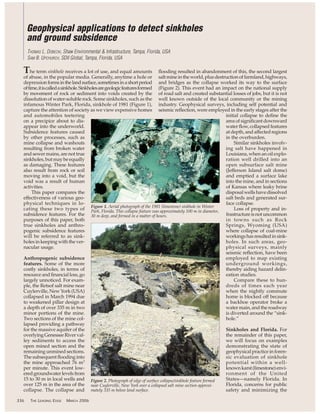
  • 1. The term sinkhole receives a lot of use, and equal amounts of abuse, in the popular media. Generally, anytime a hole or depressionformsinthelandsurface,sometimesinashortperiod oftime,itiscalledasinkhole.Sinkholesaregeologicfeaturesformed by movement of rock or sediment into voids created by the dissolution of water-soluble rock. Some sinkholes, such as the infamous Winter Park, Florida, sinkhole of 1981 (Figure 1), capture the attention of society as we view expensive homes and automobiles teetering on a precipice about to dis- appear into the underworld. Subsidence features caused by other processes, such as mine collapse and washouts resulting from broken water and sewer mains, are not true sinkholes, but may be equally as damaging. These features also result from rock or soil moving into a void, but the void was a result of human activities. This paper compares the effectiveness of various geo- physical techniques in lo- cating these two types of subsidence features. For the purposes of this paper, both true sinkholes and anthro- pogenic subsidence features will be referred to as sink- holes in keeping with the ver- nacular usage. Anthropogenic subsidence features. Some of the more costly sinkholes, in terms of resourceandfinancialloss,go largely unnoticed. For exam- ple, the Retsof salt mine near Cuylerville, NewYork (USA) collapsed in March 1994 due to weakened pillar design at a depth of over 335 m in two minor portions of the mine. Two sections of the mine col- lapsed providing a pathway for the massive aquifer of the overlyingGenesseeRiverval- ley sediments to access the open mined section and the remaining unmined sections. The subsequent flooding into the mine approached 76 m3 per minute. This event low- eredgroundwaterlevelsfrom 15 to 30 m in local wells and over 125 m in the area of the collapse. The collapse and flooding resulted in abandonment of this, the second largest saltmineintheworld,plusdestructionoffarmland,highways, and bridges as the collapse worked its way to the surface (Figure 2). This event had an impact on the national supply of road salt and created substantial losses of jobs, but it is not well known outside of the local community or the mining industry. Geophysical surveys, including self potential and seismic reflection, were employed in the early stages after the initial collapse to define the area of significant downward waterflow,collapsedfeatures at depth, and affected regions in the overburden. Similar sinkholes involv- ing salt have happened in Louisiana, when an oil explo- ration well drilled into an open subsurface salt mine (Jefferson Island salt dome) and emptied a surface lake into the mine, and in sections of Kansas where leaky brine disposalwellshavedissolved salt beds and generated sur- face collapse. Loss of property and in- frastructureisnotuncommon in towns such as Rock Springs, Wyoming (USA) where collapse of coal-mine workingshasresultedinsink- holes. In such areas, geo- physical surveys, mainly seismic reflection, have been employed to map existing underground workings, thereby aiding hazard delin- eation studies. Compare these to hun- dreds of times each year when the nightly commute home is blocked off because a backhoe operator broke a water main, and the roadway is diverted around the “sink- hole.” Sinkholes and Florida. For the remainder of this paper, we will focus on examples demonstrating the state of geophysical practice in foren- sic evaluation of sinkhole potential within a well- knownkarst(limestone)envi- ronment of the United States—namely Florida. In Florida, concerns for public safety and minimizing the Geophysical applications to detect sinkholes and ground subsidence THOMAS L. DOBECKI, Shaw Environmental & Infrastructure, Tampa, Florida, USA SAM B. UPCHURCH, SDII Global, Tampa, Florida, USA 336 THE LEADING EDGE MARCH 2006 Figure 1. Aerial photograph of the 1981 (limestone) sinkhole in Winter Park, Florida. This collapse feature was approximately 100 m in diameter, 30 m deep, and formed in a matter of hours. Figure 2. Photograph of edge of surface collapse/sinkhole feature formed near Cuylerville, New York over a collapsed salt mine section approxi- mately 335 m below land surface.
  • 2. potential threat of sinkhole damage to commercial and resi- dential properties has fueled the search for noninvasive tools that could be used to warn the public of an imminent sub- terranean threat. Florida is famous for its limestone bedrock platform and manyimpressivesinkholes.Manyofthelarge,roundsparkling lakes found scattered throughout Florida owe their origins to carbonatedissolutionactivity.Thecombinationofgeologically young and shallow limestone, mobile sandy soil overburden, and abundant groundwater yields an almost perfect recipe for limestone dissolution, subsidence, and sinkhole formation. Referring again to Figure 1, it is obvious that sinkholes can form rapidly and without concern for current land use. Because residential construction rarely includes thor- ough subsurface testing, many homes and small commer- cial structures are constructed over ancient sinkholes (paleosinkholes) that have been buried and obscured by subsequent depositional cycles of marine terrace deposits. In addition, the limestone is soluble and often acidic shal- low groundwater continues the process of dissolution and formation of new voids in the limestone. Because of these processes, the Florida legislature has included a statutory requirement that homeowner’s in- suranceincludeaprovi- sion that covers sinkhole-related dam- age. The statute cur- rently defines sinkhole activity as the move- ment of soil into voids causedbydissolutionin the underlying lime- stone. It goes on to de- fine sinkhole loss as damage to the insured structure as a result of sinkhole activity. There- fore, losses due to sub- sidence associated with mines, washouts, and other human causes are generally not covered. There are many other ways in which a depression can form or a house may experience damage from move- ment of earth materials. For example, holes, depressions, and/or damage can be related to heaving by tree roots, decaying or compress- ing organic matter (peat soils, buried wood, de- caying tree roots and stumps), raveling of soils into broken sewer lines or septic tanks, leaking or poorly con- structed water wells and swimming pools, buried construction de- bris, shrinking/ swel- ling clay soils, leaking MARCH 2006 THE LEADING EDGE 337 Figure 3. Photograph of a residential-scale sinkhole. The portable drilling rig seen within the depression was in the process of drilling/testing soils within a GPR anomaly area near a home when the drilling activity caused sudden ground subsidence. Figure 4. Example illustrat- ing the sequence of develop- ment of a cover-collapse sinkhole in Florida.
  • 3. water lines or irrigation pipes, very loose natural soils, and animal burrowing. Estimates of monetary damages caused by sinkhole activity are difficult to quantify because much information concerning property damage and payouts is proprietary. A 2002 investigation by Florida State University reported on an analysis of 877 Florida sinkhole claims filed between 1996 and 2001. Average payout per claim was US$62 628. In 2004, one of the largest of the insurers in Florida reported pay- ing out about $6 million in sinkhole claims, and it estimated that overall owner compensation for sinkhole claims could be as high as $25 million in 2004. In 2005, the Florida Legislature rewrote the law requiring sinkhole insurance. Previously, geophysical investigations were not required, but they had become “industry accepted” investigation techniques. In 2005, the statutes specified cer- tain investigation protocols, including geophysical investiga- tions, to identify anomalous conditions that might reflect sinkhole activity. Occasionally, the type, location, and degree of damage makes defensible identification of sinkhole activ- ity simple (Figure 3), but these cases are the exception and not the rule. Ground truth confirmation of the components of a sinkhole (as defined) is required, but blind drilling across a property is fruitless because of the low probability of drilling into such a potential sinkhole feature as well as the possibil- ity of breaching confining layers and exacerbating sinkhole development. Drill testing should be minimized and per- formed within anomalies interpreted from geophysical find- ings. In Figure 3, we see a portable drilling rig that has fallen into a ground depression adjacent to a home. The depression formed during the drilling of an anomalous feature detected during a geophysical survey. Geophysical surveys provide an important link in the chain of tests that will determine sink- hole activity or relate damage to some other cause. First, geologic evidence must support the assumption that we are in a geologic locale that is conducive to sinkhole gen- eration (e.g., shallow carbonates overlain by mobile sedi- ments).Giventhat,therearethreecharacteristicsunderFlorida statutes that must be present before a site can be associated with sinkhole activity (Figure 4): • There must be a void volume in the limestone that is capa- ble of accepting sediments. • There must be evidence of material raveling downward into such a void. • There must be damage consistent with sinkhole activity, or a surface depression, and/or evidence that a depres- sion is forming. The first and third criteria are of secondary importance as compared to evidence of raveling. First, it is almost impossi- ble to drill a borehole in Florida and not eventually encounter 338 THE LEADING EDGE MARCH 2006 Figure 5. Two-dimensional GPR transect showing significant depression and discontinuity of a deep clay horizon and, to a much lesser extent, distur- bance of overlying clastic sediments. Limestone bedrock (not observed) underlies this section approximately 30 m below land surface.
  • 4. a void — voids are ubiquitous so they do not define a sinkhole. Certaintypesofdamagetoastruc- ture can be construed as an indication of ground movement. Therefore, a filed damage claim identifying spe- cific types of structural damage rep- resents a testable argument that the surface is moving or has moved. Subsurface evidence of raveling, therefore, is generally the most impor- tant criterion to be resolved. The final word on raveling is determined by geotechnicaltesting(i.e.,standardpen- etration tests or cone penetrometer soundings), but the key role in apply- ing geophysics is, as usual, determin- ing the proper or optimal locations for such tests. The role of geophysical investiga- tions. “Raveling” is the process by which water transports soil down- ward into voids/cavities in underly- ing strata. The ravel zone is, therefore, a volume of soil that is looser (higher porosity) and has less subsequent strength than nonraveled soils. So the targets for subsurface testing are areas where soil layers are depressed, discontinuous, or truncated and where there is a volume of loose or low-strength soil. So, methods that are sensitive to changes in density, porosity, and strength are ideal for identification of areas for sub- surface testing. The most commonly used and recommended geophysi- cal surveys for the investigation of potential sinkhole activity include ground-penetrating radar (GPR), two-dimensional electrical resistivity tomography (ERT), and seismic methods (refraction tomography, reflection, surface wave inversion). Microgravity surveying has been used for sinkhole detection but, because of the ease and success of the other mentioned techniques, little has been done in Florida. The following will describe the application and advantages/disadvantages of each method using real data examples. GPR. GPR is the overwhelming geophysical method of choice for sinkhole investigations. This stems from Florida’s famous dry, high-resistivity surficial sands, which translate into relatively deep GPR penetration (typically 5-10 m). GPR provides the opportunity for dense data coverage (includ- ing 3D coverage), high resolution, and very good penetra- tion with quick turnaround and relatively low cost.Another plus is that GPR profiles can be acquired within some struc- tures by shooting through the floor slab. Reinforcing steel (rebar) limits the range of antenna frequencies (typically >400 MHz) that may be used to shoot through the slab. Difficulties arise when a site has shallow clay or shallow, salty ground- water. However, when the target of the investigation is to establish evidence of subsidence, the presence of clay is less of an issue than might be expected. If all we can image is the top of the clay and it can be shown that the clay is mov- ing or is locally disrupted due to raveling, the GPR section still provides useful information. A ravel zone can also be viewed directly on GPR sec- tions as a near-vertical zone of discrete scatterers and local increases in reflection amplitudes in the shallow section because of localized increases in soil porosity. Also, if fines (clay) are removed by the raveling process, such features are sometimes identified by a localized interval of increased GPR signal penetration due to the reduced electrical con- ductivity/attenuation. The GPR section of Figure 5 exhibits a depression in a strong reflection. This GPR reflection correlates with a thin clay layer identified in local drill holes. The clay horizon shows a substantial depression, but we also note that over- lying soil horizons exhibit only minor disturbance. Multiple, orthogonal GPR transects over the same general area of the single section enabled mapping of the top of this clay hori- zon (Figure 6). The surface map of this single layer exhibits a significant depression that has a quasi-circular footprint, which are key indicators that this anomalous area is a poten- tial buried sinkhole structure even though the ground sur- face is quite level. The apparent, undisturbed nature of the shallower soil horizons suggest that this may be an inactive (paleo) sinkhole, but follow up geotechnical drilling would be required within the feature to determine its potential activity. However, geophysical survey results ensure that such invasive testing is performed in optimum locations. ERT. 2D electrical resistivity tomography profiling (sur- face electrode arrays) is also used commonly for sinkhole investigations as a means of identifying the ravel zone and, under ideal circumstances (shallow limestone and large dis- solution features), the underlying void or cavity. The ravel zone is characterized by increased porosity and reduced per- centage of fines. Depending on depth to the local ground- water table, the ravel zone can either be a high-resistivity anomaly (if dry) or a low-resistivity anomaly (if saturated). Deeper void space is typically characterized by a low-resis- tivity feature indicative of carbonate materials being replaced by looser clastic sediments or by water. Of course, an air- filled void would generate a high-resistivity anomaly fea- ture, but this would not constitute a sinkhole (by legal definition) because it has not collapsed or accepted overly- ing sediments. ERT, in the context of sinkhole exploration within resi- dential or commercially developed properties, is generally more affected and, therefore, influenced by cultural noise sources (utilities, piping) and the limited areal space avail- able for surveying (considering the maximum dimension of a typical residential lot may be 20 ǂ 30 m or less and the MARCH 2006 THE LEADING EDGE 339 Figure 6. Surface representation of the top of the same deep clay horizon in Figure 5 as constructed from an orthogonal grid of GPR transects. The depression seen in the section view exhibits a nearly circular pattern in plan view, also suggesting sinkhole conditions.
  • 5. adjacent house may be only 3 m away). Also, space limita- tions mandate ERT lines be acquired so close to houses or structures that offline (3D) effects of foundations and swim- ming pool structures influence the readings and can pro- duce false anomalies. In spite of these limitations, at least one major insurer in Florida suggests a combination of GPR and ERT be used for all its sinkhole claim investigations. ERT sections acquired in a karst area but not in an urban- ized environment clearly display the typesofanomaliesroutinelyencoun- tered and confirmed as sinkholes (Figure 7). In the area where these sample data sets were acquired, dolomitic carbonates are known to exist in the upper 10 m, and expo- sures (quarries) in the area show significant karst development (dis- solution features, pinnacles). The ERTsectionsshowamantleoflower- resistivity silts and clayey sands overlying higher-resistivity dolo- mite.Anomalous areas are observed where we see penetration of lower- resistivitymaterialsintothedolomite indicating potential dissolution fea- tures that have been filled with surfi- cial sediments or areas with extensiveweatheringofthedolomite (e.g., along fractured volumes). ERT sections acquired in an urban setting (within 4 m of a house foundation) clearly possess lower signal-to-noise in comparison with sections acquired in undeveloped areas (Figure 8). We note the very high-resistivity surficial sands (a common Florida feature) and an anomalous area near the 11-m mark on the left side of the section where we see a thickening/deepening of the high-resistivity layer, possibly indicative of raveling. However, the section between 9.1 and 27.4 m is consistent with where the ERT tran- sect abuts against the footprint of the house (also indicated on Figure 8), and anomalous areas coincide with that interval. This, too, is a common observation when conducting ERT adjacent to a house foundation. Anomaliesgenerallyoccuratthecor- ner of a foundation. This suggests that the house itself, in the example of Figure 8, could be influencing the inversion results (3D effects on a 2D inversion process). However, com- plementaryGPRprofilesinthesame area plus a visible depression that was forming beneath the slab of the house (both shown on Figure 8) sug- gest that this ERT anomaly is actu- ally a raveling anomaly. Subsequent drilling confirmed this interpreta- tion.Thisexamplealsoindicateswhy multiple data sets and complemen- tary views of the subsurface are nec- essary for proper interpretation in a developed urban setting. Seismic methods. The key feature of a ravel zone that makes it an attractive target for seismic surveying is the loos- ened, weak nature of the sediments relative to adjacent, undisturbed soils. This makes a ravel zone an anomalous area where reduced seismic velocities are commonly expected and observed. In areas of shallow water table depths, this would mean that shear-wave-based seismic 340 THE LEADING EDGE MARCH 2006 Figure 7. Two examples of electrical resistivity tomography (ERT) images acquired in a rural setting within a karst geologic environment. The dolomitic bedrock is identified with the higher (>1000 ohm-m) green-to-red resistivities and the clayey soil mantle by the bluer shades (<50 ohm-m). Note in both examples the apparent breaches in the bedrock indicated by finger-like projections of lower-resistivity materials into the bedrock. Figure 8. Example data sets (ERT and GPR) acquired in close proximity to a house. The ERT shows a possible ravel zone anomaly (circled) near the 11-m mark; however, that location also corresponds to the corner of the house foundation (indicated above the ERT section). The GPR section shows a broad depression plus a discontinuity in a deep reflector that correlates with the position of the ERT anomaly. A void area beneath the house slab (photograph) found in the same general location confirms the inter- pretation of sinkhole conditions.
  • 6. methods would be particularly sensitive to the detection and mapping of such loose soil volumes. Further, because of the typically large velocity contrast between the soils and car- bonate bedrock, seismic methods are also very good at map- ping depressions on the bedrock surface. The most common seismic method utilized for sinkhole definition has been seismic refraction tomography (SRT) using S-waves, when possible. Tomographic processing of the refraction data set is required because the ravel zone will represent a local, lateral variation/anomaly in the shear- wave velocity field (and, to a lesser extent, the P-wave veloc- ity field if fully saturated) that is poorly handled by more classical ray-trace interpretation methods. Figure 9 is a P- wave refraction tomography section acquired not in Florida but in Texas where a road failure occurred associated with drilling near a salt dome structure. The section clearly shows development of a pair of lobe volumes of reduced strength/ lower-velocity materials that are extending downward into more competent, higher-velocity (redder) materials. The position and magnitude of the surface collapse is indicated by the depression in the surface topography. A unique characteristic of refraction tomography that is enticing as a future development is broadside shooting, or undershooting, where geophone spreads are extended along one side of a house and the seismic sources are deployed along the other sides. This would enable generation of a velocity map under the house. Invasive testing through floor slabs can be done (minidrills or cone penetrometer systems), but methods are limited as to where they can be applied, and they are very damaging to the floor, as one would imagine. So this potential noninvasive means to look under houses would be an attractive development. Undershooting would also offer an advantage over borehole-to-borehole seismic tomography because it would sample in a horizontal plane and thereby maximize the chance of shooting through a ver- tical, low-velocity column. Such a vertical column could fall outside of the vertical plane defined by the two boreholes. Also, boreholes are always expensive (relative to the cost of geophysical surveys of this type) and represent a potential pathway or breach in a confining layer that should be avoided when possible. Another seismic technique that has had limited applica- tion but offers great promise for defining ravel zones is the MASW (multichannel analysis of surface waves) technique. This technique also maps S-wave velocity variation but has the additional capability of detecting and mapping velocity inversions (decreases with depth) and, so, may have a unique ability to detect incipient ravel zones (i.e., sinkholes in the formative process that have yet to reach land surface). Reflection surveys have typically been applied, on a spo- radic basis, to the deep sensing of depressions on the top of rock surface or detecting cavities within the rock mass itself. With the development of tomographic imaging techniques that will better define structure in the overlying sediments, there may be increased application of reflection methods for sinkhole delineation. Summary. Sinkholes, then, regardless of their underlying cause, represent hazards that can be extremely costly and dis- ruptive to society in general, are ubiquitous in where they occur, and happen routinely. Geophysics provides important tools that can be used to: • Predict where and within what limits sinkholes are likely to occur (planning; risk assessment). • Determine the underlying cause of an existing or form- ing subsidence or depression (forensic evaluation). • Evaluate the success or failure of ground improvement programs (grouting, compaction, mechanical stabiliza- tion) intended to “fix” sinkhole conditions (remediation). The sinkhole remediation aspect is taking on renewed emphasis as communities and agencies realize that the sink- hole often offers a rapid, high-permeability pathway to intro- duce surface contaminants into the groundwater system. So while the surface depression offers a tempting area to dis- pose of old vehicles and trash, there are severe consequences lurking within such activities. Suggested reading. “Sinkholes, west-central Florida” by Tihansky (in Land Subsidence in the United States, USGS Circular 1182, 1999). “The Retsof Salt Mine Collapse” by Kappel et al. (in Land Subsidence in the United States). Mitigating Losses from Land Subsidence in the United States (Commission on Engineering and Technical Systems, National Academy Press, 1991). TLE Corresponding author: tom.dobecki@shawgrp.com MARCH 2006 THE LEADING EDGE 341 Figure 9. P-wave refraction tomography section acquired adjacent to a ground depression/sinkhole that formed adjacent to a salt dome structure in Texas. Interpreted ravel zones are indicated by the two lobate features of decreased seismic velocity. Copyright © 2006, The Society of Exploration Geophysicists