Learn the concepts of Thermodynamics on Magic Marks
CS8592 Object Oriented Analysis & Design - UNIT V
1. CS8592 Object Oriented Analysis and Design Unit V
III IT Prepared by Kaviya.P, AP/IT Page 1
CS8592 – Object Oriented Analysis and Design
UNIT V – Testing
Object Oriented Methodologies – Software Quality Assurance – Impact of object orientation on Testing
– Develop Test Cases and Test Plans
5.1 OBJECT ORIENTED METHODOLOGIES
Object Oriented methodology is a set of methods, models and rules for developing systems.
Modeling is the process of describing an existing or proposed system.
Modeling provides a means for communicating ideas in an easy to understand and unambiguous
form.
Most of the methods were similar and contained a number of minor differences among them.
Same basic concepts appeared in very different notations which caused confusion among the
users.
A method is a set of procedures in which a specific goal is approached step by step.
Methodologies
1986: Booch came up with the object-oriented design concept, the Booch method.
1987: Sally Shlaer and Steve Mellor came up with the concept of the recursive design
approach.
1989: Beck and Cunningham came up with class-responsibility-collaboration (CRC) cards.
1990: Wirfs-Brock, Wilkerson, and Wiener came up with responsibility-driven design.
1991: Peter Coad and Ed Yourdon developed the Coad lightweight and prototype-oriented
approach.
1991: Jim Rumbaugh led a team at the research labs of General Electric to develop the object
modeling technique (OMT).
1994: Ivar Jacobson introduced the concept of the use case.
Survey of some ofObject Oriented Methodologies
Many methodologies are available to choose from for system development.
The methodologies developed by Rumbaugh et al., Booch, and Jacobson which are the origins of
the Unified Modeling Language (UML) and the bases of the UA.
The Rumbaugh et al. method is well-suited for describing the object model or static structure of
the system.
The Jacobson et.al method is good for producing user-driven analysis models.
The Booch method detailed object-oriented design models.
5.1.1 The Rumbaugh et al. Object Modeling Technique
The Object Modeling Technique presented by Jim Rumbaugh and his co-workers describes a
method for analysis, design and implementation of a system using an object oriented technique.
OMT is a fast intuitive approach for identifying and modeling all the objects making up a
system.
Details such as class, attributes, method, inheritance and association also can be expressed easily.
2. CS8592 Object Oriented Analysis and Design Unit V
III IT Prepared by Kaviya.P, AP/IT Page 2
The dynamic behavior of the objects within a system can be described using the OMT dynamic
model.
Dynamic model lets you specify detailed state transitions and their descriptions within a system.
Finally a process description and consumer-producer relationships can be expressed using
OMT’s functional model.
OMT consists of four phases, which can be performed iteratively:
Analysis: The results are objects, dynamic and functional models.
System Design: The result is a structure of the basic architecture of the system.
Object Design: This phase produces a design document, consisting of detailed objects
and dynamic and functional models.
Implementation: This activity produces reusable, extendible, and robust code.
OMT separates modeling into three different parts:
An object model, presented by the object model and the data dictionary.
A dynamic model, presented by the state diagrams and event flow diagrams.
A functional model, presented by data flow and constraints.
OMT Object Model
The object model describes the structure of objects in a system.
Their identity, relationships to other objects, attributes, and operations.
The object model is represented graphically with an object diagram.
The object diagram contains classes interconnected by association lines.
3. CS8592 Object Oriented Analysis and Design Unit V
III IT Prepared by Kaviya.P, AP/IT Page 3
OMT Dynamic Model
OMT dynamic model depict states, transitions, events, and actions.
OMT state transition diagram is a network of states and events.
Each state receives one or more events, at which time it makes the transition to the next
state.
OMT Functional Model
4. CS8592 Object Oriented Analysis and Design Unit V
III IT Prepared by Kaviya.P, AP/IT Page 4
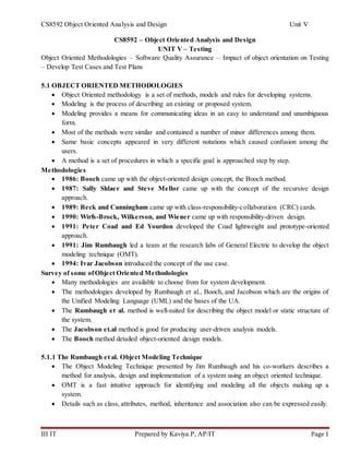
The OMT DFD shows the flow of data between different processes in a business.
DFD use four primary symbols.
Process is any function being performed. Example: verify password or PIN in the ATM
system
Data flow shows the direction of data element movement. Example: PIN code
Data store is a location where data are stored. Example: Account is a data store in the
ATM
External entity is a source or destination of a data element. Example: The ATM card
Reader
The Rumbaugh et al. - OMT DFD of the ATM System
5.1.2 The Booch Methodology
The Booch methodology covers the analysis and design phases of systems development.
Booch sometimes is criticized for his large set of symbols.
You start with class and object diagram in the analysis phase and refine these diagrams in
various steps.
The Booch method consists of the following diagrams:
– Class diagrams
– Object diagrams
– State transition diagrams
– Module diagrams
5. CS8592 Object Oriented Analysis and Design Unit V
III IT Prepared by Kaviya.P, AP/IT Page 5
– Process diagrams
– Interaction diagrams
The Booch Methodology – Object Modeling using Booch Notation
Alarm Class State Transition Diagram with Booch Notation
6. CS8592 Object Oriented Analysis and Design Unit V
III IT Prepared by Kaviya.P, AP/IT Page 6
The Booch methodology prescribes
A macro development process
o Serve as a controlling framework for the micro process and can take weeks or even months
o The primary concern of the macro process is technical management of the system
A micro development process
o Each macro development process has its own micro development process
o It is a description of day to day activities by a single or small group of software developers.
Macro Development Process consists of the following steps:
o Conceptualization
Establish the core requirements of the system
Establish a set of goals and develop a prototype to prove the concept
o Analysis and Development of the model
Class diagram is used to describe the roles and responsibilities objects are to
carry out in performing the desired behavior of the system
Object diagram is used to describe the desired behavior of the system in terms of
scenarios or use the interaction diagram
o Design or Create the System Architecture
Class diagram is used to decide what class exist and how they relate to each
other
Object diagram is used to regulate how objects collaborate
Module diagram is used to map out where each class and object should be
declared
Process diagram is determine to which processor to allocate a process
o Evolution or Implementation: Refine the system through many iterations
o Maintenance: Make localized changes the system to add new requirements and
eliminate bugs
Each macro development process has its own micro development process
The micro process is a description of the day-to-day activities by a single or small group of s/w
developers
The micro development process consists of the following steps:
o Identify classes and objects.
o Identify class and object semantics.
o Identify class and object relationships.
o Identify class and object interfaces and implementation.
5.1.3 The Jacobson et al. Méthodologies
The Jacobson et al. methodologies (e.g., OOBE, OOSE, and Objectory) cover the entire life
cycle and stress traceability between the different phases both forward and backward.
This traceability enables reuse of analysis and design work possibly in the reduction of
development time than reuse of code.
At the heart of their methodologies is the use case concept which evolved with objectory.
7. CS8592 Object Oriented Analysis and Design Unit V
III IT Prepared by Kaviya.P, AP/IT Page 7
Use cases are scenarios for understanding system requirements.
A use case is an interaction between users and a system.
The use-case model captures the goal of the user and the responsibility of the system to its users.
The use case description must contain:
– How and when the use case begins and ends?
– The interaction between the use case and its actors, including when the interaction occurs
and what is exchanged.
How and when the use case will store data in the system?
o Every single use case should describe one main flow events
o An exceptional or additional flow of events could be added
o The exceptional use case extends another use case to include the additional one
o The use-case model employs extends and uses relationships
o The extends relationship is used when you have one use case that is similar to another
use case but does a bit more.
The uses relationships reuse common behavior in different use cases.
Use cases could be viewed as a concrete or abstract.
Abstract use case is not complete and has no actors that initiate it but is used by another use case.
Object-Oriented Software Engineering: Objectory
Object-oriented software engineering (OOSE), also called Objectory, is a method of object-
oriented development with the specific aim to fit the development of large, real-time systems.
Objectory is built around several different models:
o Use case mode: Defines the outside ( actors) and inside(use case) of the system behavior
8. CS8592 Object Oriented Analysis and Design Unit V
III IT Prepared by Kaviya.P, AP/IT Page 8
o Domain object model: The object of the “real” world are mapped into the domain object
model
o Analysis object model: How the source code (implementation) should be carried out and
written
o Implementation model: Represents the implementation of the system
o Test model: Constitute the test plan, specifications, and reports
Object-Oriented Business Engineering (OOBE)
Object-oriented business engineering (OOBE) is object modeling at the enterprise level.
Use cases again are the central vehicle for modeling, providing traceability throughout the
software engineering processes.
OOBE consists of object modeling at enterprises level.
Analysis phase: The analysis process is iterative but the requirements and analysis models
should be stable before moving on to subsequent models.
Design and Implementation phases: The implementation environment must be identified for
the design model. It includes factors such as DBMS, distribution of process, constraints due to
programming language available component libraries and incorporation of graphical user
interface tools.
Testing phase: It describes several testing levels and techniques. It includes unit testing,
integration testing and system testing.
9. CS8592 Object Oriented Analysis and Design Unit V
III IT Prepared by Kaviya.P, AP/IT Page 9
5.1.4 PATTERNS
Useful information that captures the essential structure and insight of a successful family of
proven solutions to a recurring problem that arises within a certain context and system of forces.
It helps software developers resolve commonly encountered, difficult problems and a vocabulary
for communicating insight and experience about these problems and their solutions
To provide documentation to help categorize and communicate about solutions to recurring
problems.
A good pattern will do the following:
o It solves a problem - Patterns capture solutions, not just abstract principles or strategies.
o It is a proven concept - Patterns capture solutions with a track record, not theories or
speculation.
o The solution is not obvious - The best patterns generate a solution to a problem indirectly a
necessary approach for the most difficult problems of design.
o It describes a relationship - Patterns do not just describe modules, but describe deeper system
structures and mechanisms.
Generative Patterns: These patterns describe not only the recurring problem; they can also tell
how to generate something and can be observed in the resulting system architectures they helped
shape.
Non Generative Patterns: They are static and passive. They describe recurring phenomena
without necessarily saying how to reproduce them.
Patterns Template: The essential components of pattern template are Name, Problem, Context,
Forces, Solution, Resulting Context, Rationale, Related Patterns and Known uses.
Anti-Patterns: Represents “worst practice” or a “lesson leaned”. Antipattern come in two
verities: Describe a bad solution to a problem that resulted in a bad situation. Describing how to
get out of a bad situation and how to proceed from there to a good solution.
5.1.5 Frameworks
A way of presenting a generic solution to a problem that can be applied to all levels in a
development.
A single framework typically encompasses several design patterns and framework can be viewed
as the implementation of a system of design patterns.
Differences between Design Patterns and Frameworks
Design patterns are more abstract than frameworks.
Design patterns are smaller architectural elements than frameworks.
Design patterns are less specialized than frameworks.
Unified Approach
The main motivation here is to combine the best practices, processes, methodologies, and
guidelines along with UML notations and diagrams.
10. CS8592 Object Oriented Analysis and Design Unit V
III IT Prepared by Kaviya.P, AP/IT Page 10
The unified approach to software development revolves around (but is not limited to) the
following processes and components.
The UA Processes are:
Use-case driven development
Object-oriented analysis
Object-oriented design
Incremental development and prototyping
Continuous testing
The methods and technology employed includes:
Unified modeling language (UML) used for modeling
Layered approach
Repository for object-oriented system development patterns and frameworks
Promoting Component-based development
UA Object-Oriented Analysis
The use-case model captures the user requirements.
The objects found during analysis lead us to model the classes.
The interaction between objects provides a map for the design phase to model the relationships
and designing classes.
OOA Process consists of the following steps :
1. Identify the Actors
2. Develop the simple business process model using UML activity diagram
11. CS8592 Object Oriented Analysis and Design Unit V
III IT Prepared by Kaviya.P, AP/IT Page 11
3. Develop the Use Case
4. Develop interaction diagrams
5. Identify classes
UA Object-Oriented Design
UA realizes this by combining Jacobson et al.'s analysis with Booch's design concept to
create a comprehensive design process.
OOD Process consists of:
o Design classes, their attributes, methods, associations, structures and protocols, apply
design axioms
o Design the Access Layer
o Design and prototype User Interface
o User satisfaction and usability Test based on the usage / Use cases
UA - Iterative Development and Continuous Testing
The UA encourages the integration of testing plans from day 1 of the project.
Usage scenarios or Use Cases can become test scenarios
Therefore, use cases will drive the usability testing.
You must iterate and reiterate until, you are satisfied with the system.
Modeling Based on the Unified Modeling Language
The UA uses the unified modeling language (UML) to describe and model the analysis and
design phases of system development.
UA Proposed Repository
The requirement, analysis, design, and implementation documents should be stored in the
repository, so reports can be run on them for traceability.
This allows us to produce designs that are traceable across requirements, analysis, design,
implementation, and testing.
The Layered Approach to Software Development
Most systems developed with today's CASE tools or client-server application development
environments tend to lean toward what is known as two-layered architecture: interface and data.
Two-Layer Architecture
In a two-layer system, user interface screens are tied directly to the data through routines that sit
directly behind the screens.
12. CS8592 Object Oriented Analysis and Design Unit V
III IT Prepared by Kaviya.P, AP/IT Page 12
Disadvantage: This approach results in objects that are very specialized and cannot be reused easily in
other projects.
Three-Layered Architecture
Objects are completely independent of how they are represented to the user (through an
interface) or how they are physically stored.
User Interface layer
o This layer is typically responsible for two major aspects of the applications:
Responding to user interaction
Displaying business objects
Business Layer
o The responsibilities of the business layer are very straight-forward.
o Model the objects of the business and how they interact to accomplish the business
processes.
o These objects should not be responsible for:
Displaying details
Data access details
Access Layer
o Contains objects that know how to communicate with the place where the data actually
resides, whether it be a relational database, mainframe, Internet, or file.
o The access layer has two major responsibilities:
Translate request
Translate result
13. CS8592 Object Oriented Analysis and Design Unit V
III IT Prepared by Kaviya.P, AP/IT Page 13
5.2 Software Quality Assurance
SQA is planned and systematic pattern of activities necessary to provide a high degree of
confidence in the quality of a product.
It provides quality assessment of the quality control activities and determines the validity of the
data or procedures for determining quality.
Software Quality Assurance Activities
Prepare an SQA plan for a project.
Participate in the development of the projects software process description.
Review software engineering activities to verify compliance with the defined software process.
Audit designated software work products to verify compliance as part of the software process.
Ensure the deviation in software work.
Record any noncompliance and reports to the senior management.
5.2.1 Quality Assurance Tests
Debugging is a process of finding out where something went wrong and correcting the code to
eliminate the errors or bugs that cause unexpected results.
A software debugging system can provide tools for finding errors in programs and correcting
them.
Kinds of Errors
In general, software has three types of errors such as below
Language (syntax) errors are result of incorrectly constructed code, such as an incorrectly
typed keyword or punctuations. They are easiest error to be detected on simple running system.
Run–time errors are detected on running, when a statement attempts an operation that is
impossible to carry out. Example: if program tries to access a non-exist file or object, it occurs.
Logic errors occur when expected output is not formed. They can detect only by testing the
code and analyzing the results performed by intended codes.
The elimination of syntactical bug is the process of debugging, whereas detection and
elimination of logical bug is the process of testing.
Quality assurance testing can be divided into two major categories: Error–based testing and
Scenario–based testing
o Error–based testing techniques search a given class’s method for particular clues of
interests, and then describe how these clues should be tested. Example: Boundary
condition testing
o Scenario–based testing also called usage–based testing, concentrates on capturing use –
cases. Then it traces user’s task, performing them with their variants as tests. It can
identify interaction bugs. These are more complex tests tend to exercise multiple
subsystems in a single test covering higher visibility system interaction bugs
Software testing is one element of a broader topic that is often referred to as verification and
validation (V&V).
14. CS8592 Object Oriented Analysis and Design Unit V
III IT Prepared by Kaviya.P, AP/IT Page 14
o Verification refers to set of activities that ensure that software correctly implements a
specific function.
o Validation refers to different set of activities that ensure that software that has been built
is traceable to customer requirements.
5.2.2 Testing Strategies
The objective of software testing is to uncover errors.
The various testing strategies constitutes
Unit Testing: Black Box testing, White black testing
Integration Testing: Top–down testing, Bottom–up testing, Regression testing
Validation Testing: Alpha test, Beta test
System Testing: Recovery testing, Security testing, Stress testing, Performance testing
Tom Gilb argues following issues for successful software testing strategy is to be implemented:
1. Specify product requirements in a quantifiable manner long before testing commences
2. State testing objectives explicitly
3. Understand the users of s/w and develop a profile for each user category
4. Develop a testing plan that emphasizes “rapid cycle testing”
5. Build “robust” s/w that is designed to test itself
6. Use effective formal technical reviews as a filter prior to testing
7. Conduct formal technical reviews to assess the test strategy and test cases themselves
8. Develop a continuous improvement approach for testing process
Unit and integration tests concentrate on functional verification of a module and
incorporation of modules into a program structure.
Validation testing demonstrates traceability to s/w requirements.
System testing validates software once it has been incorporated into a larger system.
Unit Testing
Unit test focuses verification effort on smallest unit of software design the module. It constitutes
two inner types of testing: White box testing and Black box testing.
Black box testing: The concept of black box is used to represent a system that’s inside working
are not available for inspection. In black box testing, we try various inputs and examine resulting
output though which we learn what the box does nor how conversion takes place.
White box testing: White box testing assumes that specific logic important and must be tested to
guarantee system’s proper functioning. One form of white box testing called path testing, makes
certain that each path in an object’s method is executed at least once during testing & is of types
o Statement testing coverage: Its aim is to test every statement in object’s method at least
once.
o Branch testing coverage: Idea is to perform enough tests ensuring all branches are
perfect.
15. CS8592 Object Oriented Analysis and Design Unit V
III IT Prepared by Kaviya.P, AP/IT Page 15
Integration Testing
Integration Testing: It is a systematic technique for constructing the program structure while
conducting tests to uncover errors associated with interfacing.
The objective is to take unit tested modules and build a program structure that has been dictated
by design.
It has again 3 testing patterns: Top–down testing, Bottom – up and Regression Testing.
Top–down testing: It assumes that main logic or object interactions and system messages of
application need more testing than an individual object’s method or supporting logic. This
strategy can detect serious flaws early in implementation.
Bottom–Up testing: It starts with details of system and proceeds to higher levels by a
progressive aggregation of details until they collectively fit requirements for system i.e., start
with methods and classes then to level up. It makes sense as it checks behavior of piece of code
before it is used.
Regression testing: It is activity that helps ensure that changes (due to testing or other reasons)
do not introduce unintended behavior or additional errors.
The regression test suite contain three different classes of test cases:
o A representative sample of tests that will exercise all software functions.
o Additional tests that focus on software functions that are likely to be affected by change.
o Tests that focus on software components that have been changed.
Validation Testing
After integration testing, software is completely assembled as a package; interfacing errors have
been uncovered and corrected and final series of software tests – validating testing – begins.
It is the continuous execution on software by number of times & users.
It is again implemented either by one of two methods: Alpha testing or Beta testing.
o Alpha test is conducted in controlled environment at developer’s site by a customer. The
software is used in setting with developer “looking over shoulder” of user, recording
errors & usage problems.
o Beta test is conducted at one or more customer sites by end user(s) of the software. Its
live application of software where customer records all problems that are encountered
during beta testing and reports
System Testing
It is a series of different tests whose primary purpose is to fully exercise the computer – based
system.
The different tests in series are Recovery, security, stress and performance testing.
Recovery testing is a system test that forces software to fail in a variety of ways and verifies that
recovery is properly performed. If recovery is automatic, re-initialization, checkpoint
mechanisms, data recovery and restart are each evaluated for correctness
16. CS8592 Object Oriented Analysis and Design Unit V
III IT Prepared by Kaviya.P, AP/IT Page 16
Security testing attempts to verify that protection mechanisms built into a system will in fact
protect it from improper penetration. During this test, tester plays the role(s) of individual who
desires to penetrate system. The role of system designer is to make penetration cost greater than
value of information that will be obtained.
Stress testing executes a system in a manner that demands resources in abnormal quantity,
frequency or volume. A variation of stress testing is a technique called sensitivity testing. In
some situations, a very small range of data contained within the bounds of valid data for
programs may cause extreme and even erroneous processing.
Performance testing is designed to test run-time performance of software within context of an
integrated system. It occurs throughout all steps in testing process. Performance tests are often
coupled with stress testing and often require both hardware and software instrumentation.
5.2.3 Impact of Object Orientation on Testing
The impact of an object orientation on testing can be summarized as follows:
1. Some types of errors could become less plausible (not worth for testing)
2. Some types of errors could become more plausible (worth testing for now)
3. Some new types of errors might appear
The primary objective of testing for software is to uncover as much errors as possible with
manageable amount of efforts in realistic time span.
Various issues in object oriented testing are:
1. What should be units for object oriented testing?
2. What are the implications of encapsulation, composition, inheritance and polymorphism?
3. What are the levels of object oriented testing?
4. How to perform data flow testing?
1. Units for Object Oriented Testing
Traditional software defines unit as the smallest software component that can be compiled
and executed.
Testing focus of unit testing is considered as classes or object.
There are two advantages of choosing class as a unit of testing
o The class is used in the state chart in which the behavior of the object is represented.
o Due to testing classes under the unit testing the integration testing is clear.
2. Implication of Composition and Encapsulation on Testing
The composite relationship define the has-a relationship.
The composite object takes the ownership of the component.
Together with the goal of reuse composition creates the need for very strong unit testing.
If the encapsulation of data and methods in the class is good then such classes can be easily
composed and tested easily.
17. CS8592 Object Oriented Analysis and Design Unit V
III IT Prepared by Kaviya.P, AP/IT Page 17
3. Implication of Inheritance on Testing
The inheritance is a kind of relationship in which the specialized classes can be derived from the
generalized class.
If class is considered as unit for unit testing then it creates the problem for object-oriented testing
having inheritance relationship among the classes.
To avoid this classes are flattened. That means all attributes and methods to be inherited from the
super class needs to be included in the sub class itself and then tested.
But some kind of uncertainty remain after testing hence if there is inheritance relationship in the
design then testing becomes a complex activity.
4. Implication of Polymorphism on Testing
Polymorphism means same method can be used by different objects to achieve desired
functionality.
Polymorphism is the capability of an operation exhibiting different behavior in different
instances.
Since the programmer is no longer concerned with the internal structure of the objects, it results
in lack of controllability as actual binding of object reference is not known till run time.
It introduces undecidability concern in class based testing as it can lead to messages sent to
wrong objects.
5.2.4 Develop Test Cases and Test Plans
5.2.4.1 Develop Test Cases
Myers describes the objective of testing as follows:
o Testing is process of executing a program with the intent of finding errors.
o A good test case is one that has a high probability of detecting an as–yet undiscovered error.
o A successful test case is one that detects as as–yet undiscovered error.
A test case is a document that lays out the following:
o Test data
o Procedures/inputs
o Scenarios
o Descriptions
o Testing environment
o Expected results
o Actual results
Example
Test Case Scenario: To compare the 2 numbers
Description: To print numbers are equal or which is bigger
18. CS8592 Object Oriented Analysis and Design Unit V
III IT Prepared by Kaviya.P, AP/IT Page 18
Guidelines for developing Quality Assurance Test Cases
Freedman & Thomas have developed guidelines that have been adapted for the Unified Approach
1. Describe which feature or service (external of internal), test attempts to cover
2. If test case is based on use case it must refer to use–case name and write test plan for that piece
3. Specify what to test on which method along with test feature and expected action
4. Test normal use of the object’s methods
5. Test abnormal but reasonable use of the object’s methods
6. Test abnormal and unreasonable use of object’s methods
7. Test boundary conditions of number of parameters or input set of objects
8. Test object’s interactions & message sent among them with assist of sequence diagram
9. On doing revision, document the cases so they become the starting basis for follow–up test
10. Attempt to reach agreement on answers of what–if questions and repeat process until stabilized
11. The internal quality of software such as its reusability and extendibility should be assessed as
well
Example: Testing a File Open feature, we specify the result as follows:
1) Drop down the File menu and select Open
2) Try opening following type of files
* A file that is there (should work)
* A file that is not there (should get an error message)
* A file name with international characters (should work)
* A file type that the program does not open (should get a message or conversion dialog box)
5.2.4.2 TestPlan
A test plan is a comprehensive document that lays out all major activities associated with
a particular testing project.
The test plan need not be very large; in fact, devoting too much time to the plan can be
counterproductive. The following steps are needed to create a plan.
19. CS8592 Object Oriented Analysis and Design Unit V
III IT Prepared by Kaviya.P, AP/IT Page 19
Objectives ofcreating Test Plan
1) Create objectives of test and describe how to achieve them.
2) Development of test case: Develop test data, I/O based on domain of data & expected behavior.
3) Test analysis: It involves examination of test output and documentation of test results.
o All passed tests should be repeated with revised program called regression testing.
o Most software companies use beta testing, a popular inexpensive, effective way to test s/w
and alpha testing.
Guidelines for developing Test Plans
Thomas stated following guidelines for writing test plans
Specific appearance or format of test plan must include more details about test
It should contain a schedule and a list of required resources including number of peoples &time
Document every type of test planned with level of detail driven by several factors
A configuration control system provides a way of tracking changes to code should exist
Try to develop a habit of routinely bring test plan sync with product or product specification
At end of each moth or as reach each milestone, take time to complete routine updates
1) The methods used to design test cases in OO testing are based on the conventional methods.
However, these test cases should encompass special features so that they can be used in the
object-oriented environment.
2) It should be explicitly specified with each test case which class it should test.
3) Purpose of each test case should be mentioned.
4) External conditions that should exist while conducting a test should be clearly stated with each
test case.
5) All the states of object that is to be tested should be specified.
6) Instructions to understand and conduct the test cases should be provided with each test case.
5.2.5 Object-oriented Testing Methods
As many organizations are currently using or targeting to switch to the OO paradigm, the
importance of OO software testing is increasing.
The methods used for performing object-oriented testing are discussed in this section.
20. CS8592 Object Oriented Analysis and Design Unit V
III IT Prepared by Kaviya.P, AP/IT Page 20
State Based Testing
State-based testing is used to verify whether the methods (a procedure that is executed by an
object) of a class are interacting properly with each other.
This testing seeks to exercise the transitions among the states of objects based upon the identified
inputs.
For this testing, finite-state machine (FSM) or state-transition diagram representing the possible
states of the object and how state transition occurs is built.
In addition, state-based testing generates test cases, which check whether the method is able to
change the state of object as expected.
If any method of the class does not change the object state as expected, the method is said to
contain errors.
To perform state-based testing, a number of steps are followed, which are listed below.
1. Derive a new class from an existing class with some additional features, which are used to
examine and set the state of the object.
2. Next, the test driver is written. This test driver contains a main program to create an object,
send messages to set the state of the object, send messages to invoke methods of the class
that is being tested and send messages to check the final state of the object.
3. Finally, stubs are written. These stubs call the untested methods.
Fault-based Testing
Fault-based testing is used to determine or uncover a set of plausible faults. In other words,
the focus of tester in this testing is to detect the presence of possible faults.
Fault-based testing starts by examining the analysis and design models of OO software as
these models may provide an idea of problems in the implementation of software.
The effectiveness of this testing depends highly on tester experience in application domain
and the system under test.
This is because if he fails to perceive real faults in the system to be plausible, testing may
leave many faults undetected.
However, examining analysis and design models may enable tester to detect large number of
errors with less effort.
As testing only proves the existence and not the absence of errors, this testing approach is
considered to be an effective method and hence is often used when security or safety of a
system is to be tested.
Scenario-based Testing
Scenario-based testing is used to detect errors that are caused due to incorrect specifications and
improper interactions among various segments of the software.
Incorrect interactions often lead to incorrect outputs that can cause malfunctioning of some
segments of the software.
The use of scenarios in testing is a common way of describing how a user might accomplish a
task or achieve a goal within a specific context or environment.
21. CS8592 Object Oriented Analysis and Design Unit V
III IT Prepared by Kaviya.P, AP/IT Page 21
Note that these scenarios are more context- and user specific instead of being product-specific.
Generally, the structure of a scenario includes the following points.
o A condition under which the scenario runs.
o A goal to achieve, which can also be a name of the scenario.
o A set of steps of actions.
o An end condition at which the goal is achieved.
o A possible set of extensions written as scenario fragments.
Scenario- based testing combines all the classes that support a use-case (scenarios are subset of
use-cases) and executes a test case to test them.
Execution of all the test cases ensures that all methods in all the classes are executed at least once
during testing.
However, testing all the objects (present in the classes combined together) collectively is
difficult. Thus, rather than testing all objects collectively, they are tested using either top-down
or bottom-up integration approach.
This testing is considered to be the most effective method as scenarios can be organized in such a
manner that the most likely scenarios are tested first with unusual or exceptional scenarios
considered later in the testing process.
This satisfies a fundamental principle of testing that most testing effort should be devoted to
those paths of the system that are mostly used.
5.2.6 Challenges in Testing Object-oriented Programs
Traditional testing methods are not directly applicable to OO programs as they involve OO
concepts including encapsulation, inheritance, and polymorphism.
These concepts lead to issues, which are yet to be resolved.
Some of these issues are listed below:
o Encapsulation of attributes and methods in class may create obstacles while testing. As
methods are invoked through the object of corresponding class, testing cannot be
accomplished without object. In addition, the state of object at the time of invocation of
method affects its behavior. Hence, testing depends not only on the object but on the state
of object also, which is very difficult to acquire.
o Inheritance and polymorphism also introduce problems that are not found in traditional
software.
o Test cases designed for base class are not applicable to derived class always (especially,
when derived class is used in different context).
o Thus, most testing methods require some kind of adaptation in order to function properly
in an OO environment.