Chapter 6 earth pressure
•Download as DOCX, PDF•
5 likes•2,043 views

Shivaji University Geotechnial Engineering Notes Question answers Earth Pressure

Recommended
More Related Content
What's hot
What's hot (20)
Similar to Chapter 6 earth pressure
Similar to Chapter 6 earth pressure (20)
More from DYPCET
More from DYPCET (16)
Recently uploaded
Recently uploaded (20)
Chapter 6 earth pressure
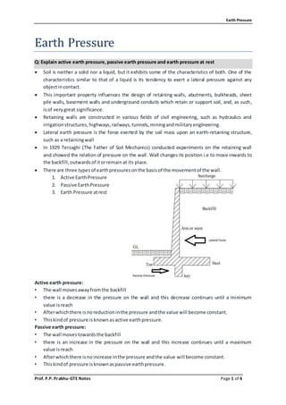
- 1. Earth Pressure Prof. P.P. Prabhu-GTE Notes Page 1 of 6 Earth Pressure Q: Explain active earth pressure,passive earth pressure and earth pressure at rest Soil is neither a solid nor a liquid, but it exhibits some of the characteristics of both. One of the characteristics similar to that of a liquid is its tendency to exert a lateral pressure against any objectincontact. This important property influences the design of retaining walls, abutments, bulkheads, sheet pile walls, basement walls and underground conduits which retain or support soil, and, as such, isof verygreat significance. Retaining walls are constructed in various fields of civil engineering, such as hydraulics and irrigationstructures,highways,railways,tunnels,miningandmilitaryengineering. Lateral earth pressure is the force exerted by the soil mass upon an earth-retaining structure, such as a retainingwall In 1929 Terzaghi (The Father of Soil Mechanics) conducted experiments on the retaining wall and showed the relation of pressure on the wall. Wall changes its position i.e to move inwards to the backfill,outwardsof itorremainat its place. There are three typesof earthpressuresonthe basisof the movementof the wall. 1. Active EarthPressure 2. Passive EarthPressure 3. Earth Pressure atrest Active earth pressure: • The wall movesawayfromthe backfill • there is a decrease in the pressure on the wall and this decrease continues until a minimum value isreach • Afterwhichthere isnoreductioninthe pressure andthe value will become constant. • Thiskindof pressure isknownasactive earthpressure. Passive earth pressure: • The wall movestowardsthe backfill • there is an increase in the pressure on the wall and this increase continues until a maximum value isreach • Afterwhichthere isnoincrease inthe pressure andthe value will become constant. • Thiskindof pressure isknownaspassive earthpressure.
- 2. Earth Pressure Prof. P.P. Prabhu-GTE Notes Page 2 of 6 Pressure at rest: • When the wall is at rest and the material is in its natural state then the pressure applied by material isknownasEarth Pressure atRest. • It isrepresentedbyPo. • Active pressure =Passive pressure ExplainCoefficientofactive,passive pressure and earth pressure at rest Coefficientofactive earth pressure at rest: Whenthe retainingwall isatrest thenthe ratiobetweenthe lateral earthpressure andthe vertical pressure iscalledthe co-efficientof the earthpressure atrest, for normally consolidated soils 𝐾0(𝑁𝐶) = 1 − 𝑠𝑖𝑛𝜑 Co-efficientofactive earth pressure: Whenthe retainingwall ismovingawayfromthe backfill the ratiobetweenlateral earthpressure and vertical earthpressure iscalledcoefficientof active earthpressure. 𝐾𝑎 = 1 − 𝑠𝑖𝑛𝜑 1 + 𝑠𝑖𝑛𝜑 = tan2 (45 𝑜 − 𝜑 2 ) Coefficientofpassive earthpressure: Whenthe retainingwall ismovingtowardsthe backfill,thenthe ratiobetween the lateralearth pressure andthe vertical earthpressure iscalledthe Coefficientof passive earthpressure. 𝐾𝑎 = 1 + 𝑠𝑖𝑛𝜑 1 − 𝑠𝑖𝑛𝜑 = tan2 (45 𝑜 + 𝜑 2 ) Q: State concept of Rankine’sand Coulomb’stheoryof earth pressure Q: Differentiate betweenRankine’sandCoulomb’stheoryof earth pressure Q: Explain Rankine’sand Coulomb’stheory of earth pressure
- 3. Earth Pressure Prof. P.P. Prabhu-GTE Notes Page 3 of 6 Rankine (1857) developedhistheoryof lateral earthpressurewhenthe backfill consistsof dry, cohesionlesssoil. The followingare the importantassumptionsinRankine’stheory: 1. The soil mass issemi-infinite,homogeneous,dryandcohesionless. 2. The ground surface isa plane whichmaybe horizontal orinclined. 3. The face of the wall incontact withthe backfill isvertical andsmooth.(Inotherwords,the frictionbetweenthe wall andthe backfill isneglected). 4. The wall yieldsaboutthe base sufficientlyforthe active pressure conditionstodevelop;if it isthe passive case thatisunderconsideration,the wall istakentobe pushedsufficiently towardsthe fill forthe passive resistance tobe fullymobilised. (Sample example) Retaining wall with soil Pressure distribution diagram The followingare the assumptionsinCoulomb’stheory: 1. The backfill soil is considered to be dry, homogeneous and isotropic; it is elastically un- deformable butbreakable,granularmaterial,possessinginternal frictionbutnoncohesion. 2. The rupture surface is assumed to be a plane for the sake of convenience in analysis. It passes through the heel of the wall. It is not actually a plane, but is curved and this is known to Coulomb. 3. The sliding wedge acts as a rigid body and the value of the earth thrust is obtained by consideringitsequilibrium. 4. The position and direction of the earth thrust are assumed to be known. The thrust acts on the back of the wall at a point one-third of the height of the wall above the base of the wall
- 4. Earth Pressure Prof. P.P. Prabhu-GTE Notes Page 4 of 6 and makes an angle δ, with the normal to the back face of the wall. This is an angle of frictionbetweenthe wall andbackfillsoil andisusuallycalled‘wallfriction’. 5. The problem of determining the earth thrust is solved, on the basis of two-dimensional case of ‘plane strain’. Thisis to say that, the retaining wall is assumed to be of greatlength and all conditions of the wall and fill remain constant along the length of the wall. Thus, a unit lengthof the wall perpendiculartothe plane of the paperisconsidered. 6. The back face of the wall isa plane. (Sample example) Retaining wall with soil
- 5. Earth Pressure Prof. P.P. Prabhu-GTE Notes Page 5 of 6 Out of syllabus (new course) Q: Explain Rebhann’sGraphical Method 1. Let ABrepresentthe backface of the wall and ADthe backfill surface 2. Draw BD inclined at φ with the horizontal from the heel B of the wall to meet the backfill surface inD. 3. Draw BK inclinedatψ (= α – δ) withBD,whichis the ψ-line. 4. Through A, draw AE parallel to the ψ-line to meet BD in E. (Alternatively, draw AE at (φ + δ) with AB to meetBD inE). 5. Describe asemi-circle onBDas diameter. 6. Erect a perpendiculartoBDat E to meetthe semi-circleinF. 7. WithB as centre andBF as radiusdraw an arc to meetBD inG 8. ThroughG, drawa parallel tothe ψ-linetomeetADinC. 9. With G as centre and GC as radius draw an arc to cut BD in L; join CL and also draw a perpendicularCMfrom C on to LG. 10. BC is the requiredrupture surface.
- 6. Earth Pressure Prof. P.P. Prabhu-GTE Notes Page 6 of 6 Q: Explain Culmann’sGraphical Method 1. Draw the groundline,φ-line,andψ-line,andthe wall face AB. 2. Choose an arbitrary failure plane BC1. Calculate weight of the wedge ABC and plot it as B-1 to a convenientscale onthe φ-line. 3. Draw 1 – 1′ parallel tothe ψ-line through1to meetBC1 in1′. 1′ is a pointonthe Culmann-line. 4. Similarly, take some more failure planes BC2, BC3, ..., and repeat the steps (ii) and (iii) to establishpoints2′,3′, ... 5. JoinB, 1′, 2′, 3′, etc.,smoothlytoobtainthe Culmanncurve. 6. Draw a tangentt-t,to the Culmannline parallel tothe φ-line. 7. Let the pointof the tangencybe F′ 8. Draw F′F parallel tothe ψ-line tomeetthe φ-line inF. 9. JoinBF′ and produce itto meetthe groundline inC. 10. BF′C represents the failure surface and FF ′ represents Pa to the same scale as that chosen to representthe weightsof wedges.