
Recommended
More Related Content
What's hot
What's hot (20)
Similar to Simplification of train loading on bridges
Similar to Simplification of train loading on bridges (20)
Recently uploaded
Recently uploaded (20)
Simplification of train loading on bridges
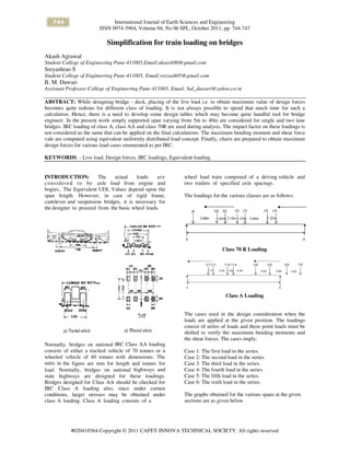
- 1. 744 International Journal of Earth Sciences and Engineering ISSN 0974-5904, Volume 04, No 06 SPL, October 2011, pp. 744-747 #020410364 Copyright © 2011 CAFET-INNOVA TECHNICAL SOCIETY. All rights reserved Simplification for train loading on bridges Akash Agrawal Student College of Engineering Pune-411005,Email:akassh90@gmail.com Sreyashrao S Student College of Engineering Pune-411005, Email:sreyash05@gmail.com B. M. Dawari Assistant Professor College of Engineering Pune-411005, Email: bal_dawari@yahoo.co.in ABSTRACT: While designing bridge - deck, placing of the live load i.e. to obtain maximum value of design forces becomes quite tedious for different class of loading. It is not always possible to spend that much time for such a calculation. Hence, there is a need to develop some design tables which may become quite handful tool for bridge engineer. In the present work simply supported span varying from 5m to 40m are considered for single and two lane bridges. IRC loading of class A, class AA and class 70R are used during analysis. The impact factor on these loadings is not considered as the same that can be applied on the final calculations. The maximum bending moment and shear force vale are computed using equivalent uniformly distributed load concept. Finally, charts are prepared to obtain maximum design forces for various load cases enumerated as per IRC. KEYWORDS: - Live load, Design forces, IRC loadings, Equivalent loading. INTRODUCTION: The actual loads are considered to be axle load from engine and bogies.. The Equivalent UDL Values depend upon the span length. However, in case of rigid frame, cantilever and suspension bridges, it is necessary for the designer to proceed from the basic wheel loads. Normally, bridges on national IRC Class AA loading consists of either a tracked vehicle of 70 tonnes or a wheeled vehicle of 40 tonnes with dimensions. The units in the figure are mm for length and tonnes for load. Normally, bridges on national highways and state highways are designed for these loadings. Bridges designed for Class AA should be checked for IRC Class A loading also, since under certain conditions, larger stresses may be obtained under class A loading. Class A loading consists of a wheel load train composed of a driving vehicle and two trailers of specified axle spacings. The loadings for the various classes are as follows: Class 70 R Loading Class A Loading The cases used in the design consideration when the loads are applied at the given position. The loadings consist of series of loads and these point loads must be shifted to verify the maximum bending moments and the shear forces. The cases imply: Case 1: The first load in the series. Case 2: The second load in the series. Case 3: The third load in the series. Case 4: The fourth load in the series. Case 5: The fifth load in the series. Case 6: The sixth load in the series. The graphs obtained for the various spans at the given sections are as given below
- 2. 745Simplification For Train Loading On Bridges International Journal of Earth Sciences and Engineering ISSN 0974-5904, Volume 04, No 06 SPL, October 2011, pp. 744-747 THE SHEAR FORCE VARIATION CHARTS Class 70 R Loading For Class 70 R loading the shear force variation with span at 0.1 L For Class 70 R loading the shear force variation with span at 0.2 L For Class 70 R loading the shear force variation with span at 0.3 L For Class 70 R loading the shear force variation with span at 0.4 L For Class 70 R loading the shear force variation with span at 0.5 L THE SHEAR FORCE VARIATION CHARTS FOR CLASS A LOADING For Class 70 R loading the shear force variation with span at 0.1 L For Class 70 R loading the shear force variation with span at 0.2 L For Class 70 R loading the shear force variation with span at 0.3 L
- 3. 746 Akash Agrawal, Sreyashrao S, B. M. Dawari International Journal of Earth Sciences and Engineering ISSN 0974-5904, Volume 04, No 06 SPL, October 2011, pp. 744-747 For Class 70 R loading the shear force variation with span at 0.4 L For Class 70 R loading the shear force variation with span at 0.5 L THE BENDING MOMENT CHARTS For Class A loading the bending moment variation with span at 0.1 L For Class A loading the bending moment variation with span at 0.2 L For Class A loading the bending moment variation with span at 0.3 L For Class A loading the bending moment variation with span at 0.4 L For Class A loading the bending moment variation with span at 0.5 L BENDING MOMENT VARIATION FOR CLASS AA LOADING For Class AA loading the bending moment variation with span at 0.1 L
- 4. 747Simplification For Train Loading On Bridges International Journal of Earth Sciences and Engineering ISSN 0974-5904, Volume 04, No 06 SPL, October 2011, pp. 744-747 For Class AA loading the bending moment variation with span at 0.2 L For Class AA loading the bending moment variation with span at 0.3 L For Class AA loading the bending moment variation with span at 0.4 L For Class AA loading the bending moment variation with span at 0.5 L CONCLUDING REMARKS With the help of above charts it becomes very easy to determine the bending moments and shear forces acting on the various spans of the bridges in case of a single train loading for Class 70 R, Class A, Class AA. The bridge can hence be designed for the maximum bending moments and shear forces acting on the various points as the load keeps on shifting and hence the critical sections can easily be indentified and precautions can be taken to avoid the load failure in such cases. In the present work simply supported span varying from 5m to 40m are considered for single and two lane bridges. IRC loading of Class A, Class AA and Class 70R are used during analysis. The impact factor on these loadings is considered here the same that can be applied on the final calculations. The maximum bending moment and shear force value are computed using influence line diagram. Finally, charts are prepared to obtain maximum design forces for various load cases enumerated as per IRC. REFERENCES [1] Standard Specifications and Code of Practice for Road Bridges Section:II Loads and Stresses (4th Revision) Indian road Congress:21-2000 [2] Standard Specifications and Code of Practice for Road Bridges Section:IIICement Concrete Plain and Reinforced 3rd Revision Indian road Congress:6-2000 [3] Design Criteria for Prestressed Concrete road Bridges Post Tensioned Concrete III Revision Indian Road Congress:18-2000 [4] Indian Standard Code Of Practice For Prestressed Concrete(First Revision)-IS:1343-1980 (Reaffirmed 2004) Edition 2.1 [5] Design of Prestressed Concrete Bridges –N Krishna Raju – Oxford and Hill Publications, 4th Edition. [6] The Design of Prestressed Concrete Bridges – Robert Benaim-Francis and Taylor Publication,4th Edition [7] Prestressed Concrete Bridges –C Menn-Springer- Verlag,Wien,Publication-1986 [8] Design of Bridge Structures-T. R. Jagadeesh, M. A. Jayaram-PHI Learning Pvt. Ltd., 2004